Zynq-7000 AP SoC - Implementing a Host PC GUI for Communication with Zynq Tech Tip
Zynq-7000 AP SoC - Implementing a Host PC GUI for Communication with Zynq Tech Tip
Zynq-7000 AP SoC - Implementing a Host PC GUI for Communication with Zynq Tech Tip
Table of Contents
Document History
| Date |
Version |
Author |
Description of Revisions |
| 29th April 2014 |
0.1 |
Upender Cherukupally |
Initial version |
Summary
The Graphical User Interface (GUI) is a software application on a host PC used to communicate with an embedded system. The GUI provides the user with interactive commands inputs and graphical representation of the results data from the target embedded system. The GUI will be interfaced to the target system using the communication protocols like UART, USB or Ethernet. This techtip explains the step by step procedure to create a simple GUI using the Visual C# to interface and communicate with the Zynq-7000 AP SoC development kit with the UART as medium of communication to the host PC
Implementation
| Implementation Details |
|
| Design Type |
PS Only |
| SW Type |
Standalone, Visula C# on windows PC |
| CPUs |
1 ARM Cortex-A9 |
| PS Features |
|
| PL Cores |
|
| Boards/Tools |
One ZC702 or One ZC706, UART, USB & Power cables |
| Xilinx Tools Version |
Vivado 2013.4 or latest |
| Other Details |
|
| Files Provided |
|
| Zynq7000AP_SoC_GUI_Ref_design.zip |
Archived file contains: 1. C# project for GUI on host PC 2. ReadyToTest Images 3. Source code of application running on Zynq-7000 AP SoC |
Block Diagram
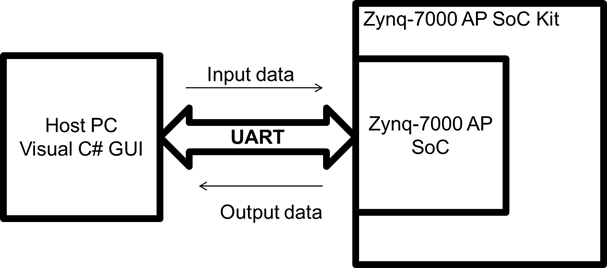
This design example uses the UART protocol to communicate data between the GUI on host PC and Zynq-7000 AP SoC. The GUI example reference design will have the following components:
On Windows Visual C# GUI
- Display the UART ports available on the host PC
- Two text boxes
- one for the input from the user and
- display the processed data from the Zynq-7000 AP SoC of the user input
- Receives the input string from user through the GUI
- Reserves the input string and sends back the reversed sting to the GUI
When user initiates the UART connection by selecting the corresponding UART port, GUI will enable the input text box for the user inputs. The user inputs will be transferred to the Zynq-7000 AP SoC and will be processed (reversed) and sends back the processed data back to the GUI through the UART port.
| Figure 1: GUI Example Block Diagram |
Step by Step Instructions
- Launch Vivado IDE Design Tool:
- On Windows 7, select Start > All Programs > Xilinx Design Tools > Vivado 2013.4 > Vivado 2013.4
- On Linux, enter Vivado at the command prompt
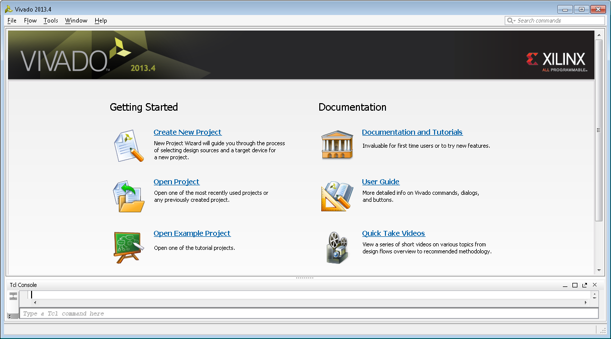
Figure 2:Vivado IDE tool launch
- Select “Create New Project” in launch window as shown in Figure 2 and new Vivado project wizard will open
- In the Project Name dialog box, type the project name (e.g. GUI_Example) and location. Ensure that Create project subdirectory is checked, and then click Next.
- In the Project Type dialog box, select RTL Project and ensure that Don’t specify the sources at this time is checked then click Next.
- In the Default Part dialog box select Boards and choose ZYNQ-7 ZC702 Evaluation Board or ZYNQ-7 ZC706 Evaluation Board. Make sure that you have selected the proper Board Version to match your hardware because multiple versions of hardware are supported in the Vivado IDE. Click Next.
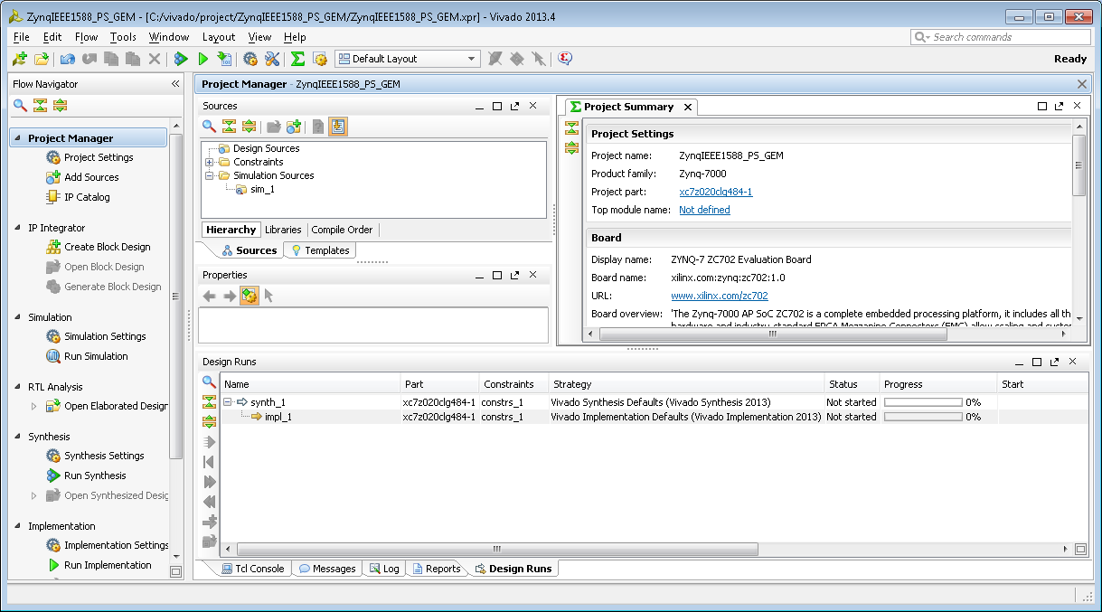
- Review the project summary in the New Project Summary dialog box before clicking Finish to create the project. Project summary window similar to Figure 3 will be opened
Figure 3: Vivado IDE Project summay - In the Project Manager wizard under IP Integrator select Create Block Design, enter the design name or leave default (design_1) in the Please specify name of the block design pop-up window and select ok
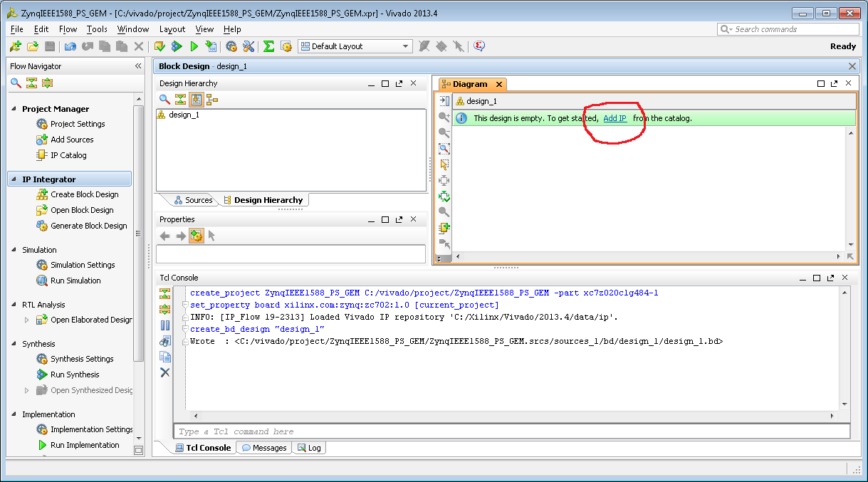
- In the desing_1 drawing view select Add IP as shown in Figure 4 and select Zynq7 Processing System in the next pop-up search window
Figure 4: Adding IP to block design - Select Run Block Automation and /processing_system7_0 as shown in Figure 5
Figure 5: Vivado block automation - In next pop-up Run Block automation make sure that apply board preset is checked and select ok
- In next window select and connect the clock inputs as shown in Figure 6
Figure 6: Vivado connecting clock inputs - Click on Generate block design and generate in next pop-up under the Flow Navigator
- Once generation is successful create the HDL wrapper as shown in Figure 7 and select the default option in next window pop-up
Figure 7: Vivado creating HDL wrapper - Select Generate block design in the IPI navigator
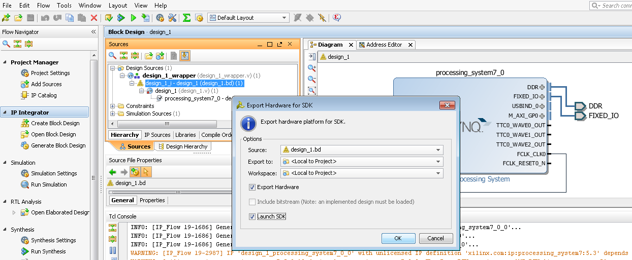
- Similarly select the Export Hardware for SDK once the HDL Wrapper is created select the options shown in the Figure 8
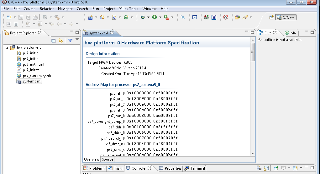
Figure 8: Vivado exporting the HW to SDK - SDK tool will be launched as shown in the Figure 9
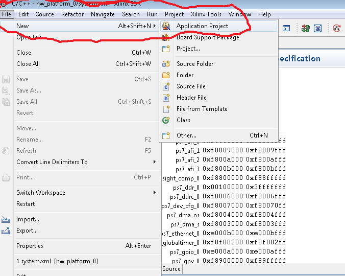
Figure 9: SDK launch - Create a new application project to create the First stage boot loader (FSBL) as shown in the Figure 10
Figure 10: SDK creating a new project - Enter the project name in next window and select Next.
- In the Template wizard select Zynq FSBL and select Finish. Then SDK builds the Zynq FSBL if auto build is enabled.
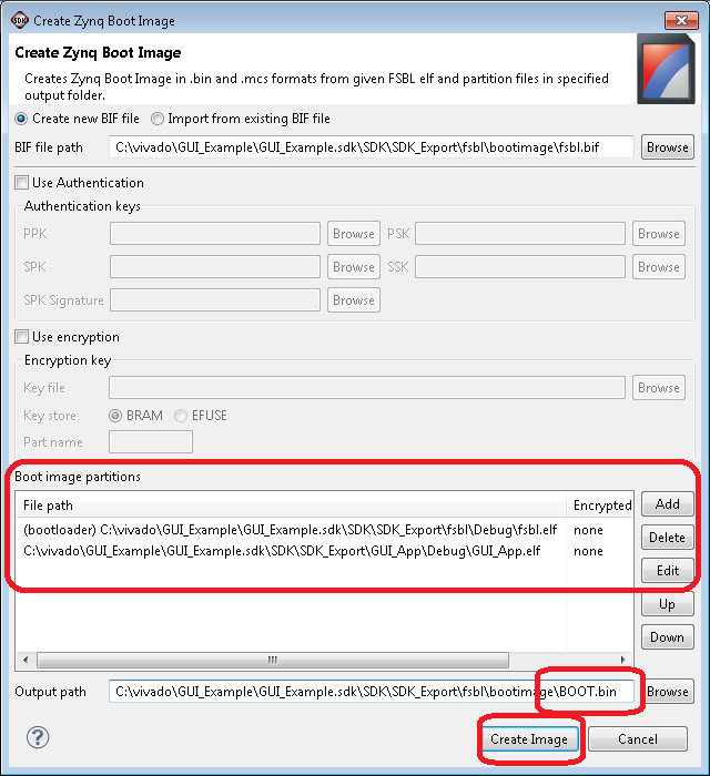
- In SDK, select Xilinx tools and Create Zynq Boot Image as shown in the following Figure 11
Figure 11: Creating Zynq-7000 AP SoC boot Image - In the next window browse the fsbl and application code elf files as shown the following Figure 12
Figure 12: Adding Images to Boot Image - Copy the BOOT.bin created in the above step into a SD card and set the SW16 switch settings to boot from SD card on Zynq kits, connect the UART cable & power cycle the Kit
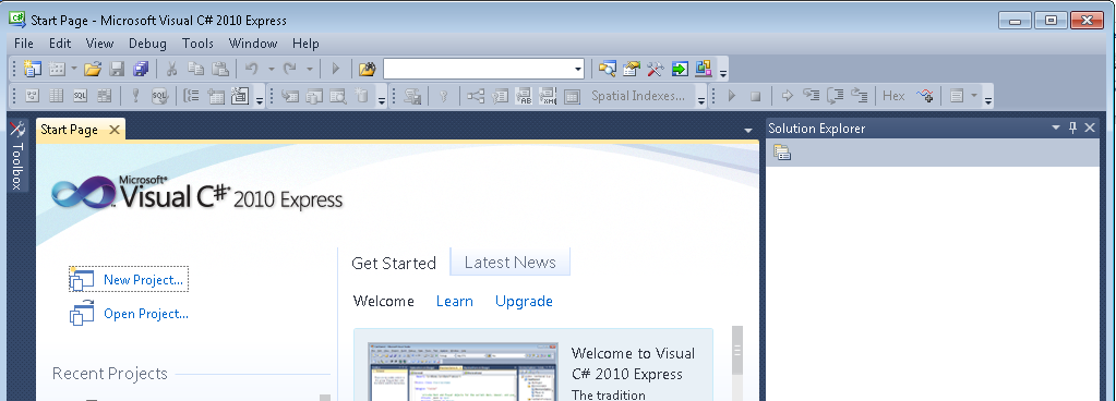
- Steps to create the GUI using the Windows Visual C#
- Launch the Visual C# and select the new project
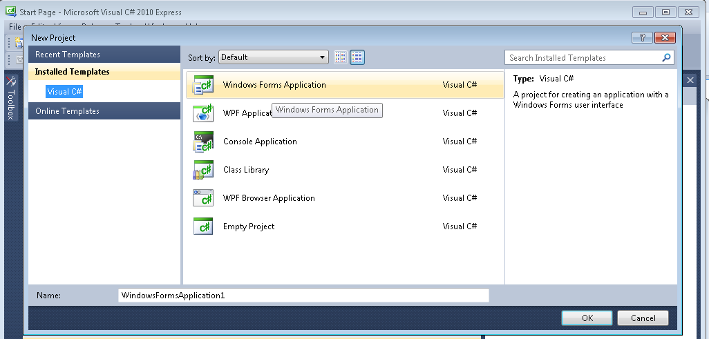
Figure 13: C# launch - Select the Windows forms application and ok button as shown in Figure 14
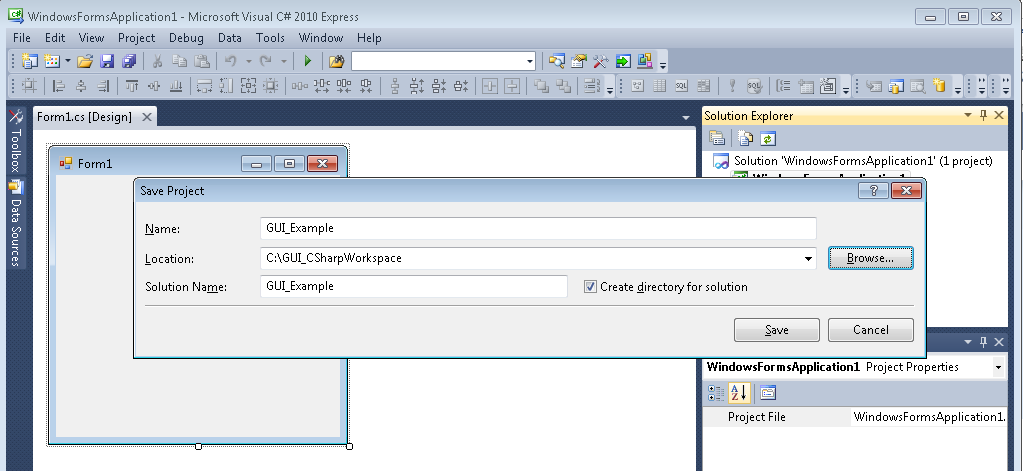
Figure 14: New Windows Forms application - Form 1 will be opened and save it with appropriate name e.g. GUI_Example in this case as shown in Figure 15
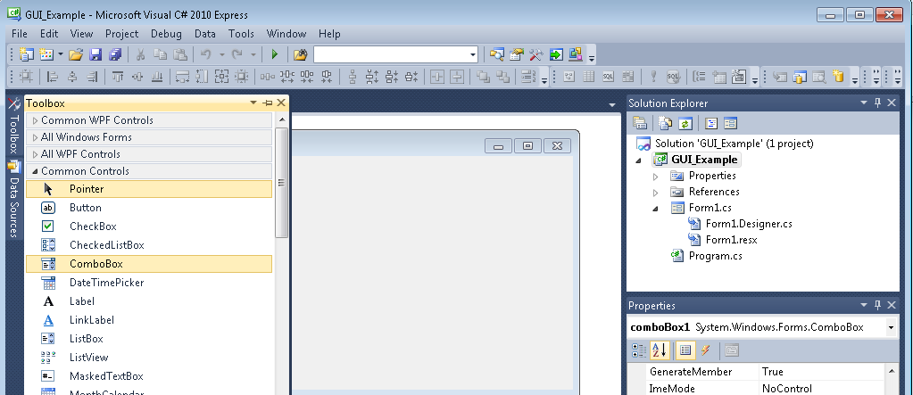
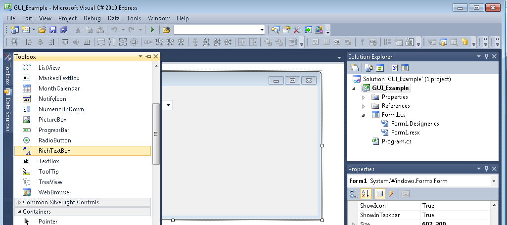
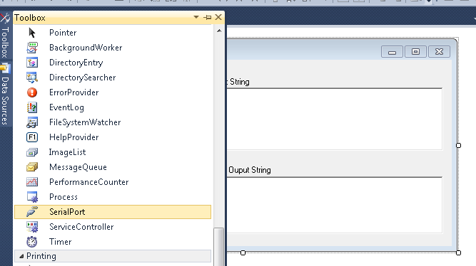
Figure 15: Starting and Saving a C# project - Add the components from toolbox bar as shown in the below Figure 16 and Figure 17 as per the project requirements. In this example we are going to add
- A Combo box (SerailComboBox) for the list of serial ports available,
- Text box for Input string from the user
- Text box for the processed output sting from the Zynq 7000 AP SoC for the given input string
- Serial port for UART communication between the GUI and Zynq7000 AP SoC 702 kit
Figure 16: Adding a Combo box to the project Figure 17: Adding a text box to the C# project
- Change the properties of the Form1, added elements as per the requirements
- Add the serial port and change name to serialMaster in properties as shown in the Figure 18
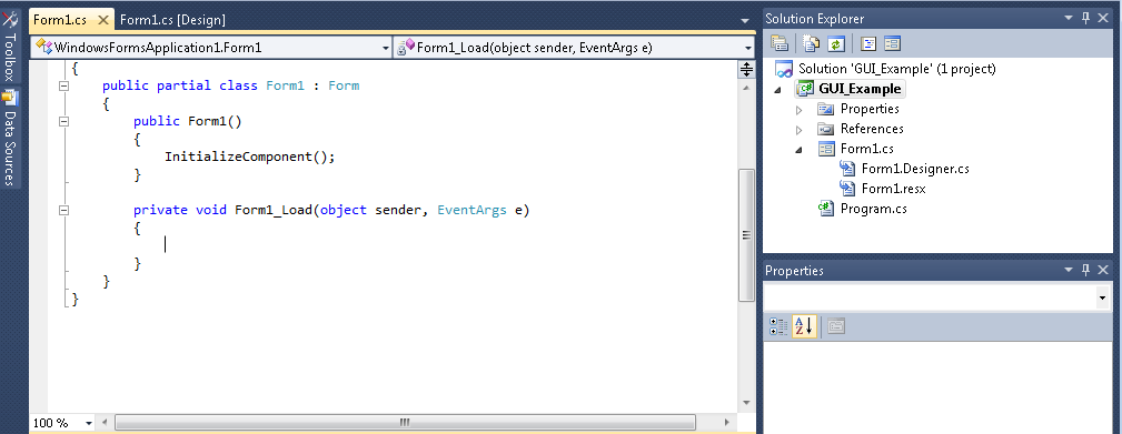
Figure 18: Adding a serial port to the C# project - Double click on Form1, the following Form1_Load() method will be opened as shown in the following Figure 19
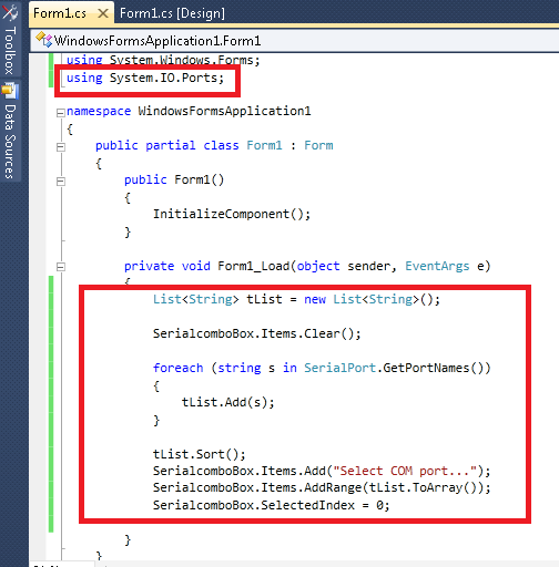
Figure 19: Form1_Load function - In the Form1.cs file add the code as highlighted in the following Figure 20. This step will add the list of available serial ports on host PC to the serial port combo box for user selection
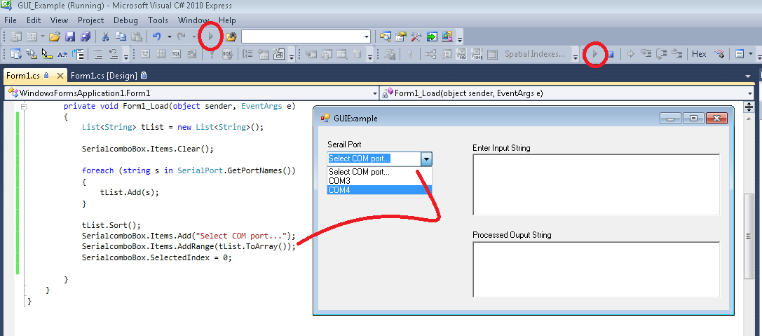
Figure 20: Updates to Form1 to add serial port - Save the project and run the project in debug mode as shown in Figure 21 to see the list of UART port available and terminate the debug session
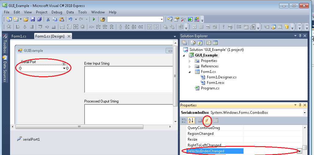
Figure 21: Steps to debug the Serial port list - Add the code for serial comport selection and dynamically check for new added comports as shown in the following Figure22 and Figure 23. Select SerialComboBox and in properties select the events and double click on SelectedIndexChanged event
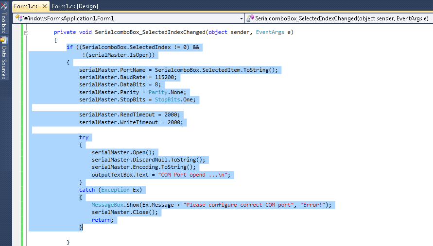
Figure 22: Enabling the event of combo box index change - The following window will be opened for adding the code for the event, add the code highlighted to the particular method
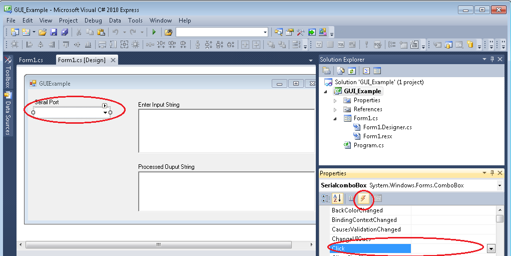
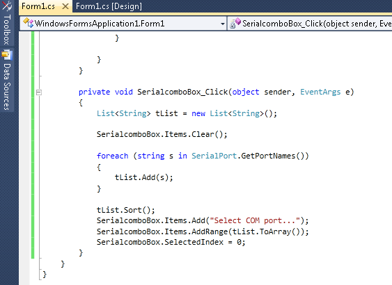
Figure 23: Code for serial port open - Following steps explains how to dynamically check for newly added comports in the ‘click’ event for the serialComboBox as shown in the Figures 24, 25
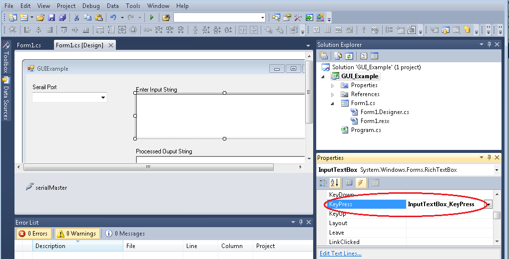
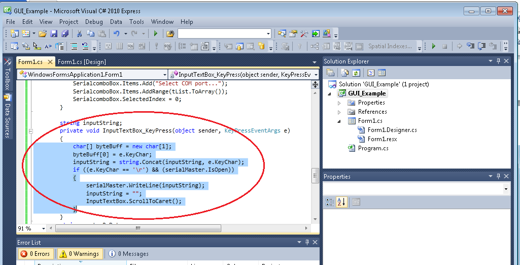
Figure 24: Enabling the client event of serial combo box Figure 25: Code for serial combox box click event to find serial ports dynamically - This step explains how to handle the user input as per our requirements, as shown in the following Figure 26 select the InputTextBox and in events double click on KeyPress event and add code for key press as shown in the Figure 27
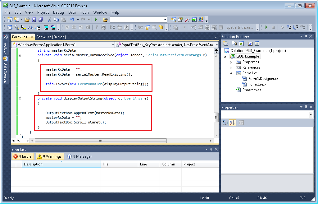
Figure 26: Enabling the event for input text box key press Figure 27: code for the input key press event of input text box - The following step explains how to handle the UART receive data in GUI, select the serialMaster (serial port instance) in GUI and in the events double click the ‘Data Received event as shown in the following Figure 28 and add the code as explained in the Figure 29
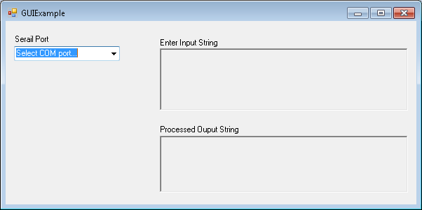
Figure 28: Enabling the serial port RX path Figure 29: Code for the serial RX data handling - The above steps complete the configuration of serial port, serial port selection combo box, input and output text boxes. Save the project and launch the debug session, the GUI will be opened as shown in the following Figure 30
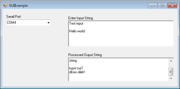
Figure 30: GUI launch - Select the COM port as per the COM port connected to Zynq-7000 AP SoC Kit. This enables the serial connection and Input and output text boxes. Enter the test string in the input string text box which will be sent to Zynq-7000 AP SoC through UART and the string will be reversed and sent back to the PC from Zynq-7000 AP SoC kit. The output processed/reversed string will be displayed on the Processed Output string text box
Figure 31: GUI in execute state
How to Expand
GUI design and implementation is depends on the project requirements and complexity may vary based on the data handling and representation like in graphs, meters etc.. Few more GUI examples available at the www.wiki.xilinx.com (e.g. http://www.wiki.xilinx.com/Zynq-7000+AP+SoC+IEEE1588+v2+Precision+Time+Protocol+Tech+Tip and Zynq7000 AP SoC Power demo )., multiple selections available,
Related content
Zynq-7000 AP SoC - Protocol Communication Between a Host PC and ZC702 Board Tech Tip
Zynq-7000 AP SoC - Protocol Communication Between a Host PC and ZC702 Board Tech Tip
More like this
Zynq-7000 AP SoC Getting Started
Zynq-7000 AP SoC Getting Started
More like this
Zynq-7000 AP SoC Development & Debug
Zynq-7000 AP SoC Development & Debug
More like this
Zynq-7000 SoC
Zynq-7000 SoC
More like this
Zynq-7000 AP SoC Boot & Config
Zynq-7000 AP SoC Boot & Config
More like this
Zynq 7000 SoC
Zynq 7000 SoC
More like this
© Copyright 2019 - 2022 Xilinx Inc. Privacy Policy
