Zynq-7000 AP SoC Low Power Techniques part 2 - Measuring ZC702 Power using TI Fusion Power Designer Tech Tip
Zynq-7000 AP SoC Low Power Techniques part 2 - Measuring ZC702 Power using TI Fusion Power Designer Tech Tip
Table of Contents
Document History
| Date |
Version |
Author |
Description of Revisions |
| 03-01-2014 |
0.1 |
E Srikanth |
Initial Draft |
1. Introduction
The ZC702 board uses power regulators and a PMBus compliant system controller from Texas Instruments to supply core and auxiliary voltages to the Zynq 7000 APSoC.There are 5 switching regulators (PTD08D210W) and 1 linear regulator which generate different voltages required for the Zynq-7000 APSoC as well as the on-board components present on the ZC702 board. The voltage and currents supplied by these voltage regulators are continuously measured and monitored by three Texas Instruments digital power controllers (UCD9248) available on the ZC702 board.
The TI Power controllers are complaint to PM Bus specification PMBus Specification 1.1 and voltage and current measurements of the TI Power controllers can be accessed via the PMBus connector, J59 using the TI Fusion USB cable and TI Fusion Digital Power Designer GUI.
In this tech tip the Zynq Base TRD has been used to demonstrate the monitor the power consumption of the Zynq7000 AP SoC and ZC702 board. The TI Fusion Digital Power Designer GUI will be used to monitor the power consumption while running the ZYNQ TRD video applications on the ZC702 board.
More details of the Zynq Base TRD are explained briefly in the About Zynq Base TRD section of this document.
Please note that the Appendix A “List of Components using the ZC702 power supplies” section of this document covers the list of components powered by different switching regulators apart from the Zynq7000 AP SoC.
The SD Card images of the TRD and the TI FUSION Project for running this techtip can be downloaded from the following link: Zynq7000AP_SoC_ZC702_Fusion_project.zip
2. Introduction to TI Fusion Digital Power Designer
The TI Fusion Digital Power Designer is the Graphical User Interface (GUI) used to configure and monitor select Texas Instruments digital power controllers and sequencer/health monitors. The application uses the PMBus protocol to communicate with the device over serial bus. Some of the tasks you can perform with the Fusion Digital Power Designer GUI include:- Turn on or off the power supply output, either through the hardware control line or the PMBus OPERATION command.
- Monitor real-time data. Items such as input voltage, output voltage, output current, temperature, and warnings/faults are continuously monitored and displayed by the GUI.
- Configure the control law accelerator (CLA) coefficients through an interactive design tool.
- Configure common operating characteristics such as Vout, warning and fault thresholds, and switching frequency.
The TI Fusion Digital Power Designer can access the PMBus by the means of using the TI USB adapter.
2.1 Hardware Requirements:
Texas Instruments USB Interface Adapter EVM– TI Part Number: USB-TO-GPIO http://www.ti.com/tool/usb-to-gpio
An Answer record for procuring the Texas Instruments USB Interface Adapter is available on Xilinx Support at the following link.
http://www.xilinx.com/support/answers/54022.html
2.2 Software requirements:
Texas Instruments TI Fusion Power Designer Software: Download it from here: http://www.ti.com/tool/fusion_digital_power_designer3. Introduction to ZC702 Power Supply Configuration
3.1 Zynq Power Supplies:
The Zynq-7000 AP SoC devices have several power domains. Figure 1 shows an overview of the power domains available on the device.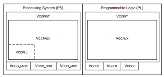 |
| Figure 1 Zynq-7000 Power Domains |
The description of the each power supply of the Zynq 7000 is as described below.
Table 1 Zynq-7000 Power Domain Description
| Name |
Type |
Description |
|---|---|---|
| VCCPINT |
PS Internal Logic Supply |
VCCPINT is a 1.0V nominal supply that powers all of the PS internal logic circuits. |
| VCCPAUX |
PS Auxiliary Logic Supply |
VCCPAUX is a 1.8V nominal supply that powers all of the PS auxiliary circuits. |
| VCCPLL |
PS PLL Supply |
VCCPLL is a 1.8V nominal supply that provides power to the three PS PLLs and additional analog circuits.. It is derived from the VCCPAUX supply |
| VCCO_MIO |
PS MIO Power Supply |
VCCO_MIO is a 1.8–3.3 volt supply which powers the I/O Bank 500 and 501, which contains PS_MIO[53:0], PS_CLK, and PS_POR_B I/Os |
| VCCO_DDR |
PS DDR I/O Supply |
VCCO_DDR is a 1.2V–1.8V nominal supply that supplies the DDR I/O bank input and output drivers. This supply sources the DDR output drivers, input receivers and termination circuitry. |
| VCCINT |
PL Internal Logic Supply |
VCCINT is a 1.0V nominal supply that powers all of the PL internal logic circuits. |
| VCCAUX |
PL Auxiliary Logic Supply |
VCCPAUX is a 1.8V nominal supply that powers all of the PL auxiliary circuits. |
| VCCO : |
PL IO Power Supply |
VCCO is a 1.2V–3.3V nominal supply that supplies the I/O banks input and output drivers. |
3.2 ZC702 Power Distribution:
The ZC702 board uses power regulators and a PMBus compliant system controller from Texas Instruments to supply core and auxiliary voltages. The ZC702 board uses 12 V Input supply to power the board.
There are 5 switching regulators (PTD08D210W) and 1 linear regulator which generate different voltages required for the Zynq700 APSoC as well as the on-board components present on the ZC702 board.
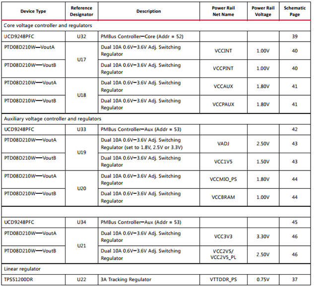 |
| Table 2 ZC702 Power Supplies |
The voltage output of these regulators are monitored and controlled by three TI power controllers (UCD9248PFC). The power distribution diagram for ZC702 board is as shown in Figure 2.
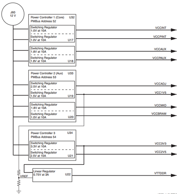 |
| Figure 2 ZC702 Power Distribution |
The three onboard TI power controllers (UCD9248) are PMBus Specification 1.1 compliant and are wired to the same PMBus. The PMBus can be accessed via the PMBus connector, J59 using the TI Fusion USB cable and TI Fusion Digital Power Designer GUI.
Please refer to the ZC702 Evaluation board user guide and schematics for information on the connections and the part numbers used on the ZC702 board.
4. Setting up the Zynq Base TRD
This techtip will use the TI Fusion Digital Power Designer and perform some power measurements while running the video demo applications using the Zynq TRD.The Zynq Base TRD is an embedded video processing application designed to showcase various features and capabilities of the Zynq Z-7020 AP SoC device for the embedded domain. The Base TRD consists of two elements: The Zynq-7000 AP SoC Processing System (PS) and a video processing pipeline implemented in Programmable Logic (PL). The AP SoC allows the user to implement a video processing algorithm that performs edge detection on an image (Sobel filter) either as a software program running on the Zynq-7000 AP SoC based PS or as a hardware accelerator inside the AP SoC based PL. The Base TRD demonstrates how the user can seamlessly switch between a software and a hardware implementation and evaluate the cost and benefit of each implementation.
In order to run this tech tip, setup the ZC702 board as explained in the “Running Video Demo Applications” section of Zynq Base TRD 2013.2 wiki page. This section also explains on video demonstration part of the TRD and running different video demonstrations out of the box.
 |
| Figure 3 Zynq Base TRD setup using ZC702 |
.
5. Implementation
| Design Type |
PL |
| SW Type |
Linux |
| CPUs |
2 ARM Cortex-A9 666MHZ |
| PS Features |
|
| PL Features |
Xylon Video Controller, Sobel Filter |
| Boards/Tools |
ZC702 |
| Xilinx Tools Version |
Vivado 2013.2 |
| Files Provided |
|
| Zynq7000AP_SoC_ZC702__Fusion_project.zip |
See Appendix B for the descriptions of the files |
6. Step by Step Instructions
6.1. Setting up the TI USB cable
- Download and install the TI Fusion Digital Power Designer from TI website on your Windows machine.
- On the TI USB Adapter connect the Ribbon Cable and the USB Cable as shown below.
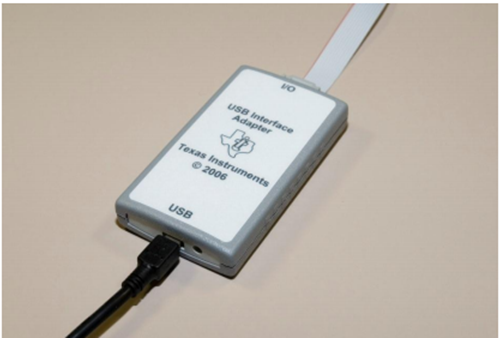
Figure 4 TI USB Cable Connections - Connect the Ribbon Cable from the TI USB cable to J59 on the ZC702 board with the red stripe towards pin 1. The header J59 is located on the underside of the board as shown below.

Figure 5 J59 Connector under ZC702 board - Connect the “A” end of the USB cable into your PC USB port.
6.2. Running the Zynq base TRD.
- Unzip the Zynq7000AP_SoC_ZC702_Fusion_project.zip file on to your hard drive.
- Copy the SD card Image files from”Zynq7000AP_SoC_ZC702__Fusion_project\trd_images” directory onto the primary partition of the SD-MMC card which is formatted as FAT32 using a SD-MMC card reader.
- Insert a SD-MMC memory card, which contains the TRD binaries, into the SD slot on the ZC702 board.Make sure the switches are set as shown in figure below, which allows the ZC702 board to boot from the SD-MMC card.

Figure 6 Setting up boot straps to boot from SD card - If an older ZC702 rev.x version boards does not have switches and contains jumpers. Use the following jumper settings: J21: 2-3, J20: 2-3, J22: 1-2, J25: 1-2, J26: 2-3
- Power on the ZC702 board.Wait for the ZC702 board to be configured and booted with Linux. After approximately 2 minutes, a XILINX ZYNQ banner displays on the monitor, as shown in the figure.The Qt-based video demonstration application starts. The GUI application shows up at the bottom of the display monitor.

Figure 7 QT window on the display connected to ZC702. - Next you will launch the TI Fusion Power designer software to monitor the different power supply rails while the TRD is running.
6.3. Setting up the TI Fusion Power designer for performing power measurements.
- Launch the TI Fusion Design Online tool by clicking on the icon installed on your desktop.
- The TI Fusion Power design tool will automatically search for the TI USB Cable as well as the three PM-Bus controllers before the GUI is completely launched.
Once the Fusion Power designer software successfully detects the PM bus controllers the GUI is launched as is displayed as follows.

Figure 9 TI Fusion Power Designer GUI default view - Select File --> Import Project to open a preloaded power supply configuration.
- Click on Select file and browse to “Zynq7000AP_SoC_ZC702__Fusion_project\ \TI_Fusion_project” directory and select the powertop.xml file.

Figure 10 Selecting the powertop.xml project file. - Select Next.
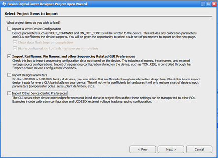
Figure 11 Select Project Items to Import Dialog - Ensure that only Import Rail Names, Pin Names and other Sequencing Related GUI Preference option is checked and remaining other options are unchecked.
- Click Next --> OK to close the dialog and you should see that the appropriate rail names have been assigned to the three onboard TI power controllers (U32 at address 52, U33 at address 53, and U34 at address 54) in the “Select Rail To Edit “ of the configure view.

Figure 12 Select Rail to Edit View
Description of the each power rail is provided in the following table.
Table 3 Power supply Details
| Device |
Rail |
Net Name |
Vout |
Regulator monitored |
Description |
|---|---|---|---|---|---|
| UCD9248@52D |
1 |
VCCINT |
1.0V |
PTD08D210W(U17) VoutA |
1.0V nominal supply of Zynq 7000 that powers all of the PL internal logic circuits. |
| UCD9248@52D |
2 |
VCCPINT |
1.0V |
PTD08D210W(U17) VoutB |
1.0V nominal supply that powers all of the PS internal logic circuits. |
| UCD9248@52D |
3 |
VCCAUX |
1.8V |
PTD08D210W(U18) VoutA |
1.8V nominal supply that powers all of the PL auxiliary circuits. |
| UCD9248@52D |
4 |
VCCPAUX |
1.8V |
PTD08D210W(U18) VoutB |
1.8V nominal supply that powers all of the PS auxiliary circuits. |
| UCD9248@53D |
1 |
VCCADJ |
2.5V |
PTD08D210W(U19) VoutA |
Supplies power to the VCCADJ power net on the ZC702 board. The list of components powered by VCCADJ net apart from the Zynq 7000 on ZC702 board is listed in the Appendix A: List of Components using the ZC702 power supplies section. |
| UCD9248@53D |
2 |
VCC1V5PS |
1.5V |
PTD08D210W(U19) VoutB |
Supplies power to the VCCO_DDR power domain of the Zynq 7000 as well as the 4 Micron DDR3 (MT41J256M8HX-15E) components on the ZC702 board. This is a 1.5V nominal supply that supplies the DDR I/O bank input, output drivers and termination circuitry. |
| UCD9248@53D |
3 |
VCC_MIO |
1.8V |
PTD08D210W(U20) VoutA |
Supplies power to the VCC_MIO power net on the ZC702 board. VCC_MIO supplies power to PS_MIO power domain of the 1.8V nominal supply that supplies power to the PS_MIO [53:0], PS_CLK, and PS_POR_B I/Os banks of Zynq 7000 as well few components on the ZC702 boards. The list of components that are powered by VCC_MIO supply apart from the Zynq 7000 on ZC702 board is listed in the Appendix: List of Components using the ZC702 power supplies section. |
| UCD9248@53D |
4 |
VCCBRAM |
1.0V |
PTD08D210W(U20) VoutB |
Supplies power to VCC_BRAM power domain of Zynq7000. VCC_BRAM is a 1.0V nominal supply that supplies power to all the Block RAMs available in the Zynq Programmable Logic. |
| UCD9248@53D |
1 |
VCC3V3 |
3.3V |
PTD08D210W(U21) VoutA |
The VCC3V3 supplies 3.3v power to the components available on the board which also includes the UCD9248 power controller itself. The list of components that are powered by VCC3V3 on ZC702 board is listed in the Appendix A: List of Components using the ZC702 power supplies section. |
| UCD9248@53D |
2 |
VCC2V5 |
2.5V |
PTD08D210W(U21) VoutB |
The VCC2V5 supplies 2.5v power to few PL IO banks as well as the components available on the board. The list of components that are powered by VCC2V5 on ZC702 board is listed in the Appendix: List of Components using the ZC702 power supplies section. |
Caution! The Texas Instruments Fusion Digital Power Designer used in this techtip can adjust the power supply outputs on the ZC702. If used improperly, it may seriously damage your ZC702. Understand the power requirements for Zynq-7000 Devices as described in the above sections before making any changes to the power supplies.
6.4. Monitoring Voltage and Current using the Fusion Power Designer.
In order to monitor each of these power supplies controlled by the UCD9248 PMBus controller, select the “Monitor” option on Fusion Power Designer Flow Navigator as shown below.This will open the monitor page of UCD9248 power rails which provides graphical representation of the input/output voltages and currents supplied to/by the PTD08D210W switching regulators as described in Table 3 Power supply Details
 |
| Figure 13 TI Fusion Designer Monitor Default view. |
Select the arrow button on the top right corner of the TI Fusion Digital Power Designer GUI. You should see a list of all the power rails available on the three UCD9248 power controller parts available on the ZC702 board.
 |
| Figure 14 Selecting different power rails to Monitor. |
You can select any of the power rail that you would like to monitor from this list.
6.5. Measuring and analyzing the power consumption of Zynq Base TRD.
- On the TI Fusion Designer GUI, Select the UCD9248 @Address 52 Rail #1 –VCCINT option in the Monitor page to monitor the VCCINT power supply.
- On the Qt-based video GUI application displayed on the bottom of the display monitor connected to the ZC702 board, Select Enable Video.
- This will start the internal test pattern generator which is displayed on the display monitor.
- Notice the change in the Pout Output Power graph on the TI Fusion Designer GUI UCD9248 Power rail #1 –VCCINT Monitor page.
Figure 16 Change in UCD9248 Power rail #1 –VCCINTpower when Enable Video option is enabled - At the same time observe the HP Port 0 AXI bandwidth usage in the QT window.

Figure 18 Change in HP0 AXI Bandwidth usage when Enable Video option is enabled
This clearly demonstrates that by starting the internal test pattern generator, the amount of data being sent to the display controller operation has increased and PL logic has more dynamic switching which has shown an increase in power consumption of the VCCINT rail which powers the internal PL logic circuits. - On the TI FUSION Designer GUI, Select the UCD9248 @Address 52 Rail #2 –VCCPINT option in the Monitor page.
This page will monitor the VCCPINT power supply which supplies power to the internal PS logic circuits. - On the Qt-based video GUI application, Change the Sobel Mode from OFF to SW.
By doing this the Sobel Video processing (edge-detection filter) is done by software code which running on the PS.Notice the change in the Pout Output Power graph on the TI Fusion Designer GUI UCD9248 Power rail #2 –VCCPINT Monitor page.
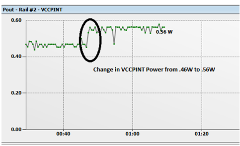
Figure 19 Increase in power due to Sobel Processing in Software - At the same time observe the CPU1 Usage usage in the QT window

This clearly demonstrates that by starting Sobel Operation in software the CPU 1 utilization has increased and the power consumption of the Processing System has also increased. - Similarly try to change the Sobel Mode from SW to HW and observe the power consumption of the UCD9248 Power rail #2 –VCCPINT rail.
7. Conclusion:
This tech tip has explained how to access the TI Power Controllers and measure the power consumed by the ZC702 board using the TI Fusion USB cable and TI Fusion Digital Power Designer.Although Zynq Base TRD has been used in this techtip to demonstrate the power consumption of the ZC702 board. The same principle can be applied to any design to measure power consumption of each rail on the ZC702 board.
8. Appendix A: List of Components using the ZC702 power supplies.
The following list provides information about the components powered by different power regulators on the ZC702 board.
8.1. Components powered by VCC3V3:
| S No |
Qty |
Designator on ZC702 |
Type |
Part Number |
Model |
Component in schematic |
|---|---|---|---|---|---|---|
| 1 |
1 |
U2 |
IC Supervisor |
MAX16025 |
Maxim |
MAX16025TE+ |
| 2 |
1 |
U3 |
IC Translator |
TXS0104E |
TI |
TXS0104EDR |
| 3 |
3 |
U4,U5,U6 |
IC Multiplexor |
CD74HC4051 |
TI |
CD74HC4051PWT |
| 4 |
1 |
U7 |
IC EEPROM |
M24C08-WDW6TP |
ST Micro |
M24C08-WDW6TP |
| 5 |
1 |
U8 |
IC Bus Transceiver |
SN74AVC2T245 |
TI |
SN74AVC2T245RSWR |
| 6 |
1 |
U9 |
IC USB interface |
USB3320 |
SMSC |
USB3320C-EZK-TR |
| 7 |
1 |
U13 |
IC Power Switch |
MIC2025 |
MICREL |
MIC2025-1YM |
| 8 |
1 |
U15 |
IC Buffer |
SN74LV541APWR |
TI |
SN74LV541APWR |
| 9 |
1 |
U16 |
IC Clock |
RTC8564JE |
EPSON |
RTC-8564JE:3:ROHS |
| 10 |
1 |
U22 |
Voltage Regulator |
TPS51200DRCT |
TI |
TPS51200DRCT |
| 11 |
1 |
U23 |
IC/Socket |
DIGILENT_USB_JTAG_2 |
DIGILENT |
JTAG-SMT1 |
| 12 |
2 |
U25,U26 |
IC Switch |
NC7SZ66P5X |
Fairchild |
NC7SZ66P5X |
| 13 |
1 |
U28 |
Oscillator |
10MHZ-810MHZ |
SILABS |
570BAB000544DG |
| 14 |
3 |
U32,U33,U34 |
IC Controller |
UCD9248PFC |
TI |
UCD9248PFC |
| 15 |
1 |
U40 |
IC Transmitter |
ADV7511 |
ANALOG |
ADV7511KSTZ-P |
| 16 |
1 |
U41 |
Memory |
N25Q128A |
MICRON |
N25Q128A11ESF40 |
| 17 |
1 |
U43 |
Oscillator |
200MHZ |
SiTime |
SIT9102AI-243N25E200.0000 |
| 18 |
1 |
U44 |
IC I2C Switch |
PCA9548ARGER |
TI |
PCA9548ARGER |
| 19 |
2 |
U56,U57 |
IC Repeater |
PCA9517 |
TI |
PCA9517DR |
| 20 |
1 |
U61 |
IC Port Expander |
TXS02612 |
TI |
TXS02612RTWR |
| 21 |
2 |
U70,U79 |
IC Translator |
TXS0108E |
TI |
TXS0108EPWR |
| 22 |
3 |
U75,U76,U77 |
IC Switch |
TS5A3359DCUR |
TI |
TS5A3359DCUR |
| 23 |
1 |
U78 |
Filter |
50MOHM |
MURATA |
BNX016-01 |
| 24 |
1 |
U80 |
IC Expander |
TCA6416A |
TI |
TCA6416APWR |
| 25 |
1 |
U81 |
IC Translator |
TXS0102 |
TI |
TXS0102DCUR |
| 26 |
3 |
U83,U84,U86 |
IC Buffer |
NC7WZ07 |
FAIRCHILD |
NC7WZ07P6X |
8.2. Components powered by VCCMIO
| S No |
Qty |
Designator |
Type |
Part No |
Model |
Component in schematic |
|---|---|---|---|---|---|---|
| 1 |
1 |
U3 |
IC Translator |
TXS0104E |
TI |
TXS0104EDR |
| 2 |
1 |
U35 |
Ethernet Xceiver |
88E1116R |
MARVELL |
88E1116RA0-NNC1C000 |
| 3 |
1 |
U36 |
IC Controller |
CP2103GM |
Silicon Labs |
CP2103-GM |
| 4 |
1 |
U41 |
Memory |
N25Q128A |
MICRON |
N25Q128A11ESF40 |
| 5 |
1 |
U61 |
IC Port Expander |
TXS02612 |
TI |
TXS02612RTWR |
| 6 |
1 |
U62 |
IC Gate |
SN74LVC1G11 |
TI |
SN74LVC1G11DCKR |
| 7 |
1 |
U64 |
IC Gate |
SN74LVC1G08 |
TI |
SN74LVC1G08DCKR |
| 8 |
1 |
U81 |
IC Translator |
TXS0102 |
TI |
TXS0102DCUR |
8.3. Components powered by VCC2V5
| S No |
Qty |
Designator |
Type |
Part No |
Model |
Component in Schematic |
|---|---|---|---|---|---|---|
| 1 |
1 |
U8 |
IC Bus Transceiver |
SN74AVC2T245 |
TI |
SN74AVC2T245RSWR |
| 2 |
1 |
U31 |
Oscillator |
12.00000MHZ |
SiTime |
SIT8102AN-23-25E-12.0000T |
| 3 |
4 |
U37,U38,U39,U71 |
IC Translator |
SN74AVC1T45 |
TI |
SN74AVC1T45DCKR |
8.4. Components powered by VCCADJ
| S No |
Qty |
Designator |
Type |
Part No |
Model |
Component in schematic |
|---|---|---|---|---|---|---|
| 1 |
2 |
U56,U57 |
IC Repeater |
PCA9517 |
TI |
PCA9517DR |
| 2 |
2 |
U70,U79 |
IC Translator |
TXS0108E |
TI |
TXS0108EPWR |
8.5. Components powered by VCC1v8
| S No |
Qty |
Designator |
Type |
Part No |
Model |
Component in Schematic |
|---|---|---|---|---|---|---|
| 1 |
1 |
U65 |
Oscillator |
33.33333MHZ |
SITIME |
SIT8103AC-23-18E-33.33333 |
8.6. Components powered by 1.5V
| S No |
Qty |
Designator |
Type |
Part No |
Model |
Component in Schematic |
|---|---|---|---|---|---|---|
| 1 |
4 |
U66,U67,U68,U69 |
IC/Socket |
MT41J256M8HX_15E |
MICRON |
MT41J256M8HX-15E |
9. Appendix B: File Descriptions
- Zynq7000AP_SoC_ZC702__Fusion_project \ TI_Fusion_project\powertop.xml
- TI Fusion Power Supply Project for ZC702.
- Zynq7000AP_SoC_ZC702__Fusion_project \ trd_images
- Contains Zynq Base TRD sdcard images files.
© Copyright 2019 - 2022 Xilinx Inc. Privacy Policy