USB Host System Setup
This page describes the system setup to connect a USB device to a Virtex-5 board.
Table of Contents
Equipment
The system setup is the same for both the ML505 board and the ML507 board. To connect a USB device to the ML50x board, you need the following supplies:- SMSC daughter board. This is the PHY card for the USB Host controller. You can get this daughter board from http://www.digilentinc.com. The part number is EVB-USB3300-XLX.
- mini-A to A USB adaptor. You can get this adaptor cable from http://www.vernier.com/accessories/access.html?usb-mini&template=basic.html. Or, a shorter version of mini-B to A adaptor from http://www.sfcable.com/cable/p/30U1-05300.html. It is not an issue whether it is mini-A to A or mini-B to A, because our USB Host is not OTG, so there is no danger of getting into the confusion on who is host.
Physical Connection
The following figure shows how the USB Host controller core, which resides in FPGA, is connected to a USB device. Note that the links between J5/J6 on ML50x board to J1 on SMSC board is conceptual, it should be direct connection between J5/J6 and J1.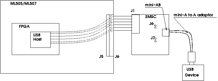
Connection Setup
There are three aspects to setup the connections:
- Setup connection from the USB host controller to J6 header on ML50x board
- Setup connections on the SMSC daughter board
- Connect the SMSC daughter board to ML50x board
We will talk in more details for each aspect in the following.
Setup connection from the USB host controller to J6 header on ML50x board
There are 13 IO signals from the USB host controller that are connected to the J6 header on the ML50x board. The following table shows the connections between the USB host controller to the J6 header, and to J1 on the SMSC board.
| USB Host signals | FPGA pins | J6 on ML50x | J1 on SMSC |
|---|---|---|---|
| PHY_Reset | H33 | 2 | 3 |
| PHY_Nxt | F34 | 4 | 6 |
| ULPI_Clock | H34 | 6 | 9 |
| ULPI_Dir | G33 | 8 | 12 |
| ULPI_Stp | G32 | 10 | 15 |
| ULPI_Data<7> | H32 | 12 | 18 |
| ULPI_Data<6> | J32 | 14 | 21 |
| ULPI_Data<5> | J34 | 16 | 24 |
| ULPI_Data<4> | L33 | 18 | 27 |
| ULPI_Data<3> | M32 | 20 | 30 |
| ULPI_Data<2> | P34 | 22 | 33 |
| ULPI_Data<1> | N34 | 24 | 36 |
| ULPI_Data<0> | AA34 | 26 | 39 |
The following is an excerpt from system.ucf file that specify the connections. The file:
##############################################################################
#### Start Module USB PHY ULPI constraints ##########################
Net xps_usb_host_0_ULPI_Clock_pin LOC=H34;
Net xps_usb_host_0_ULPI_Clock_pin IOSTANDARD = LVCMOS33;
NET "xps_usb_host_0_ULPI_Clock_pin" CLOCK_DEDICATED_ROUTE = FALSE;
Net xps_usb_host_0_ULPI_Clock_pin TNM_NET = xps_usb_host_0_ULPI_Clock_pin;
TIMESPEC TS_xps_usb_host_0_ULPI_Clock_pin = PERIOD xps_usb_host_0_ULPI_Clock_pin 16667 ps;
Net xps_usb_host_0_USB_PHY_Reset_pin LOC=H33;
Net xps_usb_host_0_USB_PHY_Reset_pin IOSTANDARD = LVCMOS33;
Net xps_usb_host_0_ULPI_Dir_pin LOC=G33;
Net xps_usb_host_0_ULPI_Dir_pin IOSTANDARD = LVCMOS33;
Net xps_usb_host_0_ULPI_Nxt_pin LOC=F34;
Net xps_usb_host_0_ULPI_Nxt_pin IOSTANDARD = LVCMOS33;
Net xps_usb_host_0_ULPI_Stp_pin LOC=G32;
Net xps_usb_host_0_ULPI_Stp_pin IOSTANDARD = LVCMOS33;
Net xps_usb_host_0_ULPI_Data_pin<7> LOC=H32;
Net xps_usb_host_0_ULPI_Data_pin<7> IOSTANDARD = LVCMOS33;
Net xps_usb_host_0_ULPI_Data_pin<6> LOC=J32;
Net xps_usb_host_0_ULPI_Data_pin<6> IOSTANDARD = LVCMOS33;
Net xps_usb_host_0_ULPI_Data_pin<5> LOC=J34;
Net xps_usb_host_0_ULPI_Data_pin<5> IOSTANDARD = LVCMOS33;
Net xps_usb_host_0_ULPI_Data_pin<4> LOC=L33;
Net xps_usb_host_0_ULPI_Data_pin<4> IOSTANDARD = LVCMOS33;
Net xps_usb_host_0_ULPI_Data_pin<3> LOC=M32;
Net xps_usb_host_0_ULPI_Data_pin<3> IOSTANDARD = LVCMOS33;
Net xps_usb_host_0_ULPI_Data_pin<2> LOC=P34;
Net xps_usb_host_0_ULPI_Data_pin<2> IOSTANDARD = LVCMOS33;
Net xps_usb_host_0_ULPI_Data_pin<1> LOC=N34;
Net xps_usb_host_0_ULPI_Data_pin<1> IOSTANDARD = LVCMOS33;
Net xps_usb_host_0_ULPI_Data_pin<0> LOC=AA34;
Net xps_usb_host_0_ULPI_Data_pin<0> IOSTANDARD = LVCMOS33;
#### END Module USB PHY ULPI constraints ##########################
Setup connections on the SMSC daughter board
The SMSC daughter board can be configured to be a PHY for a USB device or a PHY for a USB host. In our case, it needs to be a PHY for a USB host. To configure it to be a PHY for a USB host, use a jumper for the J7 connector.The SMSC daughter board can also be configured to use external power, in our case, we use the power from ML50x. To do this, use a jumper for the J6 connector.
Connect the SMSC daughter board to ML50x board
The SMSC J1 connector is attached to the top 13 rows (3 pins per row) of the J5/J6 header of the ML50x board. By doing so, the J5 connector is providing power to the SMSC daughter board.Important: Please ensure that the daughter board has the J1 connector properly aligned on the Baseboard J5/J6 header before powering up the system. An improper connection can lead to permanent damage to the daughter board when power is applied.
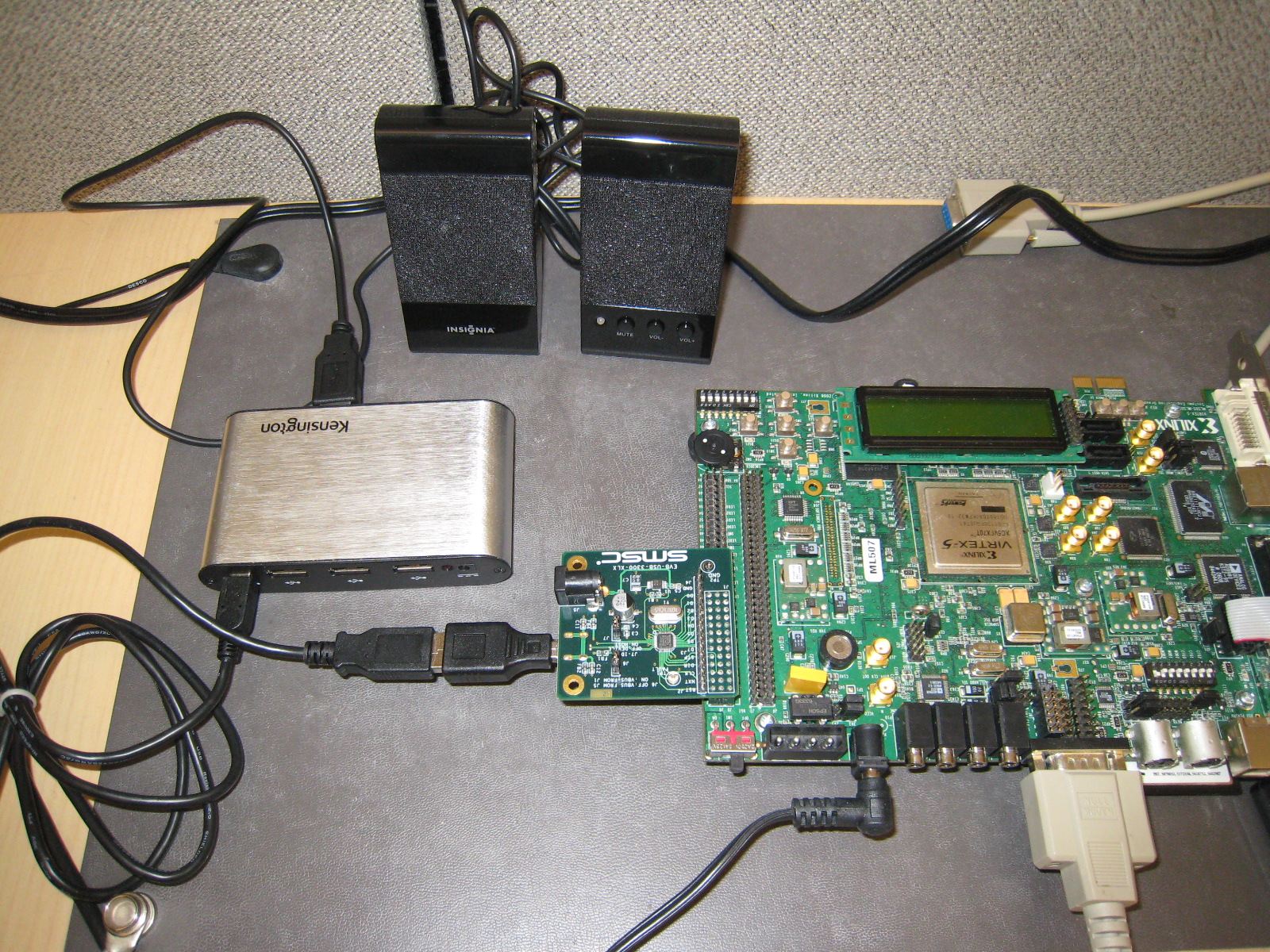
The following picture shows the connection layout. From the ML507 board, the following items are connected: SMSC daughter board, mini-B to A adaptor, A to mini-B adaptor cable, HS hub, FS speakers.
MHS file snippets
The bus connection for USB host requires a bus master interface to the memory controller. We present here the MHS file snippets from EDK projects for ML505 and ML507. Because ML505 uses MicroBlaze processor and MPMC memory controller, and ML507 uses PowerPC processor, the connections are a little bit different between the two boards. On ML505, the master bus interface is setup on the MPMC controller; and on ML507, it is setup on the PowerPC processor.ML505 (MicroBlaze system):
The following is the MHS snippet for MPMC with USB host controller. To configure MPMC, right click the mpmc instance in your EDK project, and add a new port for it. After the configuration, click on the new port and ask for a new connection. In this case, we get plb_v46_0 as the bus name.
BEGIN mpmc
...
BUS_INTERFACE XCL0 = microblaze_0_IXCL
BUS_INTERFACE XCL1 = microblaze_0_DXCL
BUS_INTERFACE SPLB2 = plb_v46_0
BUS_INTERFACE SPLB3 = mb_plb
...
END
BEGIN xps_usb_host
PARAMETER INSTANCE = xps_usb_host_0
PARAMETER HW_VER = 1.01.a
PARAMETER C_SPLB_BASEADDR = 0x82400000
PARAMETER C_SPLB_HIGHADDR = 0x824001FF
BUS_INTERFACE SPLB = mb_plb
BUS_INTERFACE MPLB = plb_v46_0
PORT USB_PHY_Reset = xps_usb_host_0_USB_PHY_Reset
PORT ULPI_Clock = xps_usb_host_0_ULPI_Clock
PORT ULPI_Dir = xps_usb_host_0_ULPI_Dir
PORT ULPI_Nxt = xps_usb_host_0_ULPI_Nxt
PORT ULPI_Stp = xps_usb_host_0_ULPI_Stp
PORT Host_Intr_Out = xps_usb_host_0_Host_Intr_Out
PORT ULPI_Data = xps_usb_host_0_ULPI_Data
END
ML507 (PowerPC system):
The following is the MHS snippet for the PowerPC processor. To add a new slave port on the processor, click on its SPLB1 port, ask for a new connection. In this case, we get splb1_plbv46 as the new bus name.BEGIN ppc440_virtex5 ... BUS_INTERFACE SPLB1 = splb1_plbv46 ... END
BEGIN xps_usb_host
PARAMETER INSTANCE = xps_usb_host_0
PARAMETER HW_VER = 1.01.a
PARAMETER C_SPLB_BASEADDR = 0x82400000
PARAMETER C_SPLB_HIGHADDR = 0x824001ff
PARAMETER C_SUPPORT_USB_FS = 1
PARAMETER C_USE_PHY_BUS_PWR = 0
PARAMETER C_EXT_VBUS_VALID = 1
BUS_INTERFACE SPLB = plb_v46_0
BUS_INTERFACE MPLB = splb1_plbv46
PORT Host_Intr_Out = xps_usb_host_0_Host_Intr_Out
PORT USB_PHY_Reset = xps_usb_host_0_USB_PHY_Reset
PORT ULPI_Clock = xps_usb_host_0_ULPI_Clock
PORT ULPI_Dir = xps_usb_host_0_ULPI_Dir
PORT ULPI_Nxt = xps_usb_host_0_ULPI_Nxt
PORT ULPI_Stp = xps_usb_host_0_ULPI_Stp
PORT ULPI_Data = xps_usb_host_0_ULPI_Data
END
Related Links
© Copyright 2019 - 2022 Xilinx Inc. Privacy Policy