Zynq-7000 AP SoC - Protocol Communication Between a Host PC and ZC702 Board Tech Tip
Zynq-7000 AP SoC - Protocol Communication Between a Host PC and ZC702 Board Tech Tip
Table of Contents
Document History
| Date |
Version |
Author |
Description of Revisions |
| 27 May 2014 |
0.0 |
Prush |
Initial Version |
| 11 June, 2014 |
0.1 |
Upender |
Added Command and response structures |
Introduction
The host machine communicates with the application running on ZC702 board through UART channel. The GUI running on the target machine sends appropriate commands to the target application based on the user selection. For the GUI to successfully send command and receive a response a simple protocol is designed in the power demo setup. This Techtip explains this protocol that is used for command and response.Block Diagram
This design example uses the UART protocol to communicate data between the GUI on host PC and Zynq-7000 AP SoC. The GUI example reference design will have the following components- 1. On Windows Visual C# GUI
- a. Display the UART ports available on the host PC,
- b. Two text boxes
ii. display the processed data from the Zynq-7000 AP SoC of the user input
- 2. Application running on Zynq-7000 AP SoC
- a. Receives the input string from user through the GUI
- b. Reserves the input string and sends back the reversed sting to the GUI
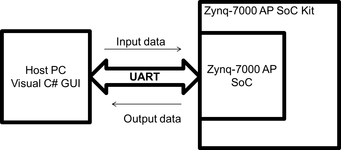
Figure1: GUI example block diagram
Communication Protocol through UART
The command packet starts with “SOC” delimiter, short for Start Of Command and ends with “EOC” delimiter short for End of Command. The data between SOC and EOC is the actual command that the application will look for.
| S |
O |
C |
X |
X |
X |
E |
O |
C |
After executing the command received from the HOST, the UART application will send out the response in the following two formats. The format of the response when there is an error message is as mentioned below.
| E |
R |
R |
ANY |
STR |
ING |
… |
E |
O |
R |
The format of the response after successful completion of the command is as mentioned below. This response packet will be send continuously at a rate of 2Hz, such that the GUI updates the values of voltage, current and power graph twice in a second. The response packet starts with a “SOR” delimiter short for Start Of Response and end with a “EOR” delimiter short for “End Of Response”.
| S |
O |
R |
nVoltage |
nCurrent |
nPower |
Additional Data |
E |
O |
R |
The actual data that the GUI will use to update the graph is highlighted in yellow in the above table. The data includes Voltage, Current, Power for all 10 voltage rails and additional data which includes CPU frequency, DDR frequency, CPU utilization, Total Power consumed, MAX power consumed and temperature. Total Power is the total power consumed on all the rails at that instant and MAX power is the highest “Total Power” during the life of the application. The data in the response packet is with a precision of 2 decimal places.
Example Commands
1) Change CPU frequency to 222 MHz
| S |
O |
C |
1 |
1 |
x |
E |
O |
C |
2) Change CPU frequency to 333 MHz
| S |
O |
C |
1 |
2 |
x |
E |
O |
C |
3) Change CPU frequency to 667 MHz
| S |
O |
C |
1 |
3 |
x |
E |
O |
C |
1) Change CPU load to idle (no load)
| S |
O |
C |
1 |
x |
1 |
E |
O |
C |
2) Run Spec2000 load on one core
| S |
O |
C |
1 |
x |
2 |
E |
O |
C |
1) Run Spec2000 load on two cores
| S |
O |
C |
1 |
x |
3 |
E |
O |
C |
Example Response
SOR:1.00:255.00:255.47:1.00:274.69:274.55:1.80:15.31:27.47:1.80:84.06:150.90:2.5 1:12.19:30.59:1.50:417.19:625.09:1.81:6.88:12.40:1.00:8.75:8.73:3.29:357.50:1173 .65:2.50:7.81:19.52:666.00:533.00:0.00:0.00:2578.36:2578.36:25.17:EOR
Power Demo GUI input commands
 |
| Figure 2 : Power demo GUI Command Input |
Power Demo GUI inputs commands and possible values for each parameter in command.
The list is not limited to the below table. There will be many combinations of commands with different values shown in the table below
| PS Configuration |
PL Configuration |
|||||||
| S/No |
COMMANDS |
PS FREQUENCY INDEX |
PS LOAD INDEX |
PL FREQUENCY INDEX |
PL UTILIZATION INDEX |
ACCUMULATOR |
LFSR |
TOGGLE FLIP-FLOP |
| 1 |
SOC1111111EOC |
1(667MHz) |
1 |
1 |
1 |
UN CHECKED |
UN CHECKED |
UN CHECKED |
| 2 |
SOC1211111EOC |
2(333MHz) |
1 |
1 |
1 |
UN CHECKED |
UN CHECKED |
UN CHECKED |
| 3 |
SOC1311111EOC |
3(222MHz) |
1(CPU_IDLE) |
1 |
1 |
UN CHECKED |
UN CHECKED |
UN CHECKED |
| 4 |
SOC1121111EOC |
1 |
2(Spec 2000:1 Load) |
1 |
1 |
UN CHECKED |
UN CHECKED |
UN CHECKED |
| 5 |
SOC1131111EOC |
1 |
3(Spec 2000:2 Load) |
1 |
1 |
UN CHECKED |
UN CHECKED |
UN CHECKED |
| 6 |
SOC114111EOC |
1 |
4(STANDBY) |
1(0MHz) |
1 |
UN CHECKED |
UN CHECKED |
UN CHECKED |
| 7 |
SOC1112111EOC |
1 |
1 |
2(50MHz) |
1 |
UN CHECKED |
UN CHECKED |
UN CHECKED |
| 8 |
SOC1113111EOC |
1 |
1 |
3(100MHz) |
1 |
UN CHECKED |
UN CHECKED |
UN CHECKED |
| 9 |
SOC1114111EOC |
1 |
1 |
4(150MHz) |
1 |
UN CHECKED |
UN CHECKED |
UN CHECKED |
| 10 |
SOC1115111EOC |
1 |
1 |
5(200MHz) |
1(0%) |
UN CHECKED |
UN CHECKED |
UN CHECKED |
| 11 |
SOC1111211EOC |
1 |
1 |
1 |
2(25%) |
UN CHECKED |
UN CHECKED |
UN CHECKED |
| 12 |
SOC1111311EOC |
1 |
1 |
1 |
3(50%) |
UN CHECKED |
UN CHECKED |
UN CHECKED |
| 13 |
SOC1111411EOC |
1 |
1 |
1 |
4(75%) |
UN CHECKED |
UN CHECKED |
UN CHECKED |
| 14 |
SOC1111511EOC |
1 |
1 |
1 |
5(100%) |
UN CHECKED |
UN CHECKED |
UN CHECKED |
| 15 |
SOC1111121EOC |
1 |
1 |
1 |
1 |
UN CHECKED |
UN CHECKED |
CHECKED |
| 16 |
SOC1111131EOC |
1 |
1 |
1 |
1 |
UN CHECKED |
CHECKED |
UN CHECKED |
| 17 |
SOC1111141EOC |
1 |
1 |
1 |
1 |
UN CHECKED |
CHECKED |
CHECKED |
| 18 |
SOC1111151EOC |
1 |
1 |
1 |
1 |
CHECKED |
UN CHECKED |
UN CHECKED |
| 19 |
SOC1111161EOC |
1 |
1 |
1 |
1 |
CHECKED |
UN CHECKED |
CHECKED |
| 20 |
SOC1111171EOC |
1 |
1 |
1 |
1 |
CHECKED |
CHECKED |
UN CHECKED |
| 21 |
SOC1111181EOC |
1 |
1 |
1 |
1 |
CHECKED |
CHECKED |
CHECKED |
Power Demo GUI output response structure and details
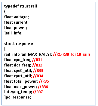
Response values from the target are separated with colon as shown below.
C# program running on host PC will interpret the values and updates the GUI graphs and corresponding text boxes
 |
| Code Snippet for output response |
The response string from the Zynq target will have 37 status values.Below is the description about the each response value.
| Response Number |
Description |
| R1 |
Rail VccInt: Voltage |
| R2 |
Rail VccInt: Current |
| R3 |
Rail VccInt: Power |
| R4 |
Rail VccPInt: Voltage |
| R5 |
Rail VccPInt: Current |
| R6 |
Rail VccPInt: Power |
| R7 |
Rail VccAux: Voltage |
| R8 |
Rail VccAux: Current |
| R9 |
Rail VccAux: Power |
| R10 |
Rail VccPAux: Voltage |
| R11 |
Rail VccPAux: Current |
| R12 |
Rail VccPAux: Power |
| R13 |
Rail Vadj: Voltage |
| R14 |
Rail Vadj: Current |
| R15 |
Rail Vadj: Power |
| R16 |
Rail VcoDDR: Voltage |
| R17 |
Rail VcoDDR: Current |
| R18 |
Rail VcoDDR: Power |
| R19 |
Rail VccMIO: Voltage |
| R20 |
Rail VccMIO: Current |
| R21 |
Rail VccMIO: Power |
| R22 |
Rail VccBRAM: Voltage |
| R23 |
Rail VccBRAM: Current |
| R24 |
Rail VccBRAM: Power |
| R25 |
Rail Vcc3.3V: Voltage |
| R25 |
Rail Vcc3.3V: Current |
| R27 |
Rail Vcc3.3V: Power |
| R28 |
Rail Vcc2.5V: Voltage |
| R29 |
Rail Vcc2.5V: Current |
| R30 |
Rail Vcc2.5V: Power |
| R31 |
CPU Frequncy |
| R32 |
DDR Frequncy |
| R33 |
CPU0 Utilization |
| R34 |
CPU1 Utilization |
| R35 |
Total Power |
| R36 |
Max Power |
| R37 |
Zynq Die Temparature |
© Copyright 2019 - 2022 Xilinx Inc. Privacy Policy