Zynq-7000 AP SoC Low Power Techniques part 4 - Measuring ZC702 Power with a Linux Application Tech Tip
Zynq-7000 AP SoC Low Power Techniques part 4 - Measuring ZC702 Power with a Linux Application Tech Tip
Table of Contents
Document History
| Date |
Version |
Author |
Description of Revisions |
|---|---|---|---|
| 7/1/2014 |
0.1 |
E.Srikanth |
Intial Draft |
| 20/1/2014 |
0.2 |
E.Srikanth |
Fixed Screenshots |
Acknowledgement:
Thanks to Rob Armstrong for the core code contributions.1. Description
The ZC702 board uses power regulators and a PMBus compliant system controller from Texas Instruments to supply core and auxiliary voltages to the Zynq 7000 APSoC.There are 5 switching regulators (PTD08D210W) and 1 linear regulator which generate different voltages required for the Zynq-7000 APSoC as well as the on-board components present on the ZC702 board. The voltage and currents supplied by these voltage regulators are continuously measured and monitored by three Texas Instruments digital power controllers (UCD9248) available on the ZC702 board. The Zynq7000 uses PMBus protocol to communicate with the power controllers over I2C bus connected to the I2C interface of the Zynq Processing system.This techtip explains the steps to develop a Linux application that reads the power values measured by the Texas Instruments digital power controllers (UCD9248) on ZC702 and converts them to real world values and display it on the ZC702 UART terminal. The application is run on the Zynq Base TRD in order to demonstrate the power consumption of the Zynq7000 AP SoC and ZC702 board.More details of the Zynq Base TRD are explained briefly in the About Zynq Base TRD section of this document.
The SD Card images of the TRD and the C source files for running this techtip can be downloaded from the following link: Zynq7000AP_SoC_ZC702_pwr_monitor_Linux.zip
Please note that the Appendix A “List of Components using the ZC702 power supplies” section of this document covers the list of components powered by different switching regulators apart from the Zynq7000 AP SoC.
1.1. ZC702 Power Distribution
The ZC702 board uses power regulators and a PMBus compliant system controller from Texas Instruments to supply core and auxiliary voltages.
The ZC702 board uses 12V Input supply to power the board. There are 5 switching regulators (PTD08D210W) and 1 linear regulator which generate different voltages required for the Zynq700 APSoC as well as the on-board components present on the ZC702/706 board.
The voltage output of these regulators are monitored and controlled by three TI power controllers (UCD9248PFC). The power distribution diagram for ZC702 board is as shown in Figure 1.
The three onboard TI power controllers are wired to the same PMBus and can be accessed via TI Semiconductor PCA9548 1-to-8 channel I2C bus multiplexer (U44) from the I2C interface of the Zynq 7000 AP SoC. The bus multiplexer can operate at speeds up to 400 kHz.
The I2C bus multiplexer switch address is at 0x74 (0b01110100) and must be addressed and configured to select the desired downstream device.
The PMBus of the PMBus controller (UCD9248) has been connected to Channel 7 of the I2C bus switch as shown below in the following figure.
The UCD9248 is compliant with the PMBus Specification 1.1. The PMBus is a serial interface specifically designed to support power management. It is based on the SMBus interface that is built on the I2C physical specification. The UCD9248 supports revision 1.1 of the PMBus standard. Wherever possible, standard PMBus commands are used to support the function of the device. These commands are defined in the UCD92xx PMBUS Command Reference, in accordance with the Compliance section of the PMBus specification.
The UCD9248 provides output voltage and current parameters in Linear format defined in Section 7.3.1 of the PMBus specification. The linear format uses a 16-bit unsigned mantissa for each parameter, along with an exponent that is shared by all the voltage or current related parameters. The exponent is reported in the bottom 5 bits of the parameter. In the UCD9248, this exponent is a read-only parameter whose value is fixed at –12. This allows setting voltage-related variables over a range from 0 to 15.9997V, with a resolution of 0.244mV.
The voltage value is calculated using the equation
Voltage = V × 2^X
Where Voltage is the parameter of interest, in volts, V is a 12-bit unsigned binary integer mantissa, and X is the signed 5-bit twos-complement binary integer exponent from VOUT_MODE register.
For current parameter, the UCD9248 supports the Linear Data Format described in section 6.1 of the PMBus specification. This linear format is a two-byte value that contains an 11-bit, twos-complement mantissa and a 5-bit, twos-complement exponent.
The relationship between the IOUT_MODE parameter and the Current value is given by the formula:
Current = Y × 2^X
Where “Current” is the real world value, Y is an 11-bit signed 2s-complement binary integer mantissa, and X is the signed 5-bit twos-complement binary integer exponent of the IOUT_MODE register.
Documentation describing PMBUS programming for the UCD9248 digital power controller is available at TI page www.ti.com/fusiondocs.Please refer to the ZC702 Evaluation board user guide and schematics for information on the connections and the part numbers used on the ZC702 board.
2. Implementation
| Implementation Details |
|
|---|---|
| Design Type |
PL |
| SW Type |
Linux |
| CPUs |
2 ARM Cortex-A9 666MHZ |
| PS Features |
|
| PL Features |
Xylon Video Controller, Sobel Filter |
| Boards/Tools |
ZC702 |
| Xilinx Tools Version |
Vivado 2013.2 |
| Files Provided |
|
| Zynq7000AP_SoC_ZC702_pwr_monitor_Linux.zip |
See Appendix B for the descriptions of the files |
3. Software Details:
The power monitor Linux application uses kernel IIC commands to read/write the regulators directly and convert the results into floating point in user space. The linear11ToFloat function in the powertop.c file will convert the IOUT_MODE register of the UCD9248 digital power controller to real world current value. The power monitor application reads the voltage and current information of the power supply regulators monitored by the UCD9248 Power controllers, calculates the average power of individual supply and finally calculates the total power consumed by the ZC702 board. These values are updated for every 1s.
The list of power supply regulators monitored by the UCD9248 power controllers is as shown below.
| Device |
Rail |
Net Name |
Vout |
Regulator monitored |
Description |
|---|---|---|---|---|---|
| UCD9248@52D |
1 |
VCCINT |
1.0V |
PTD08D210W(U17) VoutA |
1.0V nominal supply of Zynq 7000 that powers all of the PL internal logic circuits. |
| UCD9248@52D |
2 |
VCCPINT |
1.0V |
PTD08D210W(U17) VoutB |
1.0V nominal supply that powers all of the PS internal logic circuits. |
| UCD9248@52D |
3 |
VCCAUX |
1.8V |
PTD08D210W(U18) VoutA |
1.8V nominal supply that powers all of the PL auxiliary circuits. |
| UCD9248@52D |
4 |
VCCPAUX |
1.8V |
PTD08D210W(U18) VoutB |
1.8V nominal supply that powers all of the PS auxiliary circuits. |
| UCD9248@53D |
1 |
VCCADJ |
2.5V |
PTD08D210W(U19) VoutA |
Supplies power to the VCCADJ power net on the ZC702 board. The list of components powered by VCCADJ net apart from the Zynq 7000 on ZC702 board is listed in the Appendix A: List of Components using the ZC702 power supplies section. |
| UCD9248@53D |
2 |
VCC1V5PS |
1.5V |
PTD08D210W(U19) VoutB |
Supplies power to the VCCO_DDR power domain of the Zynq 7000 as well as the 4 Micron DDR3 (MT41J256M8HX-15E) components on the ZC702 board. This is a 1.5V nominal supply that supplies the DDR I/O bank input, output drivers and termination circuitry. |
| UCD9248@53D |
3 |
VCC_MIO |
1.8V |
PTD08D210W(U20) VoutA |
Supplies power to the VCC_MIO power net on the ZC702 board.VCC_MIO supplies power to PS_MIO power domain of the 1.8V nominal supply that supplies power to the PS_MIO [53:0], PS_CLK, and PS_POR_B I/Os banks of Zynq 7000 as well few components on the ZC702 boards.The list of components that are powered by VCC_MIO supply apart from the Zynq 7000 on ZC702 board is listed in the Appendix: List of Components using the ZC702 power supplies section. |
| UCD9248@53D |
4 |
VCCBRAM |
1.0V |
PTD08D210W(U20) VoutB |
Supplies power to VCC_BRAM power domain of Zynq7000. VCC_BRAM is a 1.0V nominal supply that supplies power to all the Block RAMs available in the Zynq Programmable Logic. |
| UCD9248@53D |
1 |
VCC3V3 |
3.3V |
PTD08D210W(U21) VoutA |
The VCC3V3 supplies 3.3v power to the components available on the board which also includes the UCD9248 power controller itself. The list of components that are powered by VCC3V3 on ZC702 board is listed in the Appendix A: List of Components using the ZC702 power supplies section. |
| UCD9248@53D |
2 |
VCC2V5 |
2.5V |
PTD08D210W(U21) VoutB |
The VCC2V5 supplies 2.5v power to few PL IO banks as well as the components available on the board. The list of components that are powered by VCC2V5 on ZC702 board is listed in the Appendix A: List of Components using the ZC702 power supplies section. |
4. Setting up the Zynq Base TRD
This techtip will use the power monitor Linux application to perform some power measurements while running the video demo applications using the Zynq TRD.
The Zynq Base TRD is an embedded video processing application designed to showcase various features and capabilities of the Zynq Z-7020 AP SoC device for the embedded domain. The Base TRD consists of two elements: The Zynq-7000 AP SoC Processing System (PS) and a video processing pipeline implemented in Programmable Logic (PL). The AP SoC allows the user to implement a video processing algorithm that performs edge detection on an image (Sobel filter) either as a software program running on the Zynq-7000 AP SoC based PS or as a hardware accelerator inside the AP SoC based PL. The Base TRD demonstrates how the user can seamlessly switch between a software and a hardware implementation and evaluate the cost and benefit of each implementation.
In order to run this tech tip, setup the ZC702 board as explained in the “Running Video Demo Applications” section of Zynq Base TRD 2013.2wiki page. This section also explains on video demonstration part of the TRD and running different video demonstrations out of the box.
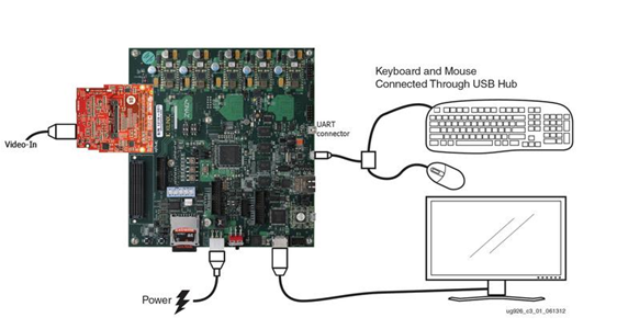
Figure 3. Zynq Base TRD setup using ZC702
5. Step by Step Instructions
5.1.Compiling the Linux Application
- Copy the Zynq7000AP_SoC_ZC702_pwr_monitor_Linux.zip file to your hard drive and unzip the file to C drive.
- Launch the SDK tool and browse to C:\ Zynq7000AP_SoC_ZC702_pwr_monitor_Linux\workspace” location to create your work space directory.
- After the SDK tool is launched. Close the Welcome page to view your workspace.
- Create a new application project.
- Select File > New > Application Project. The New Project wizard opens.
- Use the information in the table below to make your selections in the wizard screens.
| WizardScreen |
SystemProperty |
SettingorCommandtoUse |
| ApplicationProject |
Project Name |
power_monitor |
| UseDefaultLocation |
Select this option |
|
| HardwarePlatform |
ZC702_hw_platform(pre-defined) |
|
| Processor |
PS7_cortexa9_0 |
|
| OSPlatform |
Linux |
|
| Language |
C |
|
| Templates |
AvailableTemplates |
Linux EmptyApplication |
- Click Finish.
- The New Project Wizard closes and SDK creates the power_monitor Linux project
- The SDK tool automatically imports the ZC702 Hardware Platform and creates the power_monitor Linux project
- In the Project Explorer tab, expand the power_monitor project, right-click the src directory, and select Import to open the Import dialog box.
- Expand General in the Import dialog box and select File System.
- Click Next.
- Add the files present in “C:\Zynq7000AP_SoC_ZC702_pwr_monitor_Linux\sw\srcs\” directory and click Finish.

Figure 4. Importing the sources to the empty project - SDK automatically builds the application and displays the status in the console window
- You should see an error during the compilation indicating that it is unable to determine the pow() function.
- This is because the SDK is not able to search the math library in its compilation path.
- Expand the power_monitor --> src and open power_monitor.c.
- Observe the readVoltage and readCurrent function at line number 180 and 206 respectively.
- Observe the linear11ToFloat function at line number 154 and look at how the linear format is converted to real world format.
- After reviewing the code, close the file.
- In the Project Explorer tab, right click on the power_monitor project and select C/C++ BUILD Settings.
- In the power_monitor settings dialog, select Libraries under ARM Linux gcc linker.
- Add the math library by selecting the add button in the Libraries section and enter ’m’ and click ok.
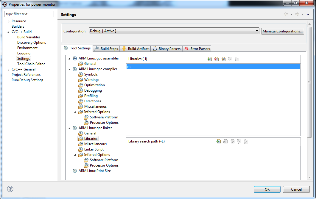
Figure 5. Setting up the math library - Now the SDK builds the application successfully.
- The powertop.elf is successfully build into “C:\Zynq7000AP_SoC_ZC702_pwr_monitor_Linux\\workspace\powertop\Debug” directory.
5.2. Running the Zynq base TRD.
- Copy all the files from ” \Zynq7000AP_SoC_ZC702_pwr_monitor_Linux\sd_card_images” directory onto the primary partition of the SD-MMC card which is formatted as FAT32 using a SD-MMC card reader.
- Copy the powertop.elf file also from “C:\Zynq7000AP_SoC_ZC702_pwr_monitor_Linux\\workspace\powertop\Debug directory to the SD-MMC memory card.
- Insert the SD-MMC memory card, which contains the TRD binaries and the power.elf file, into the SD slot on the ZC702 board.Make sure the switches are set as shown in figure below, which allows the ZC702 board to boot from the SD-MMC card.
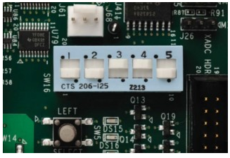
Figure 6 Setting up boot straps to boot from SD card - If an older ZC702 rev.x version boards does not have switches and contains jumpers. Use the following jumper settings:< J21: 2-3, J20: 2-3, J22: 1-2, J25: 1-2, J26: 2-3
- Open a Serial Terminal (Like Hyperterminal or Teraterm) configured at following settings to view the serial messages of the ZC702
* Baudrate: 115200
* No of bit s: 8
* Parity : 1
* Flow Control : NONE - Power on the ZC702 board.Wait for the ZC702 board to be configured and booted with Linux.
- You should the linux booting in the serial console and finally halt at the petalinux console login.
- Login to Petalinux console using the following user credentials.
zc702 login : root
password : root - At the same time a XILINX ZYNQ banner displays on the monitor, as shown in the figure.The Qt-based video demonstration application starts. The GUI application shows up at the bottom of the display monitor.
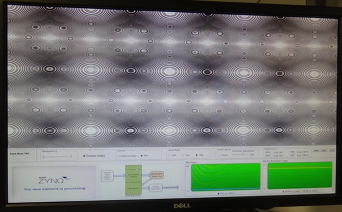
Figure 7 QT window on the display connected to ZC702.
5.3. Running the Power Monitoring Application
- Mount the SD card from the serial terminal using the following command.
mount –t vfat /dev/mmcblk0p1 /mnt - cd to the /mnt directory and execute the power_monitor.elf file.
cd /mnt
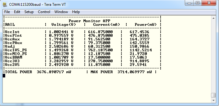
./power_monitor.elf - Observe the message in the serial console to view the voltage , current and average power consumed by each of the power supply on ZC702 board.
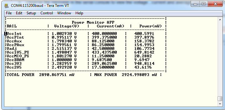
Figure8: Power Monitor APP Test Results. - In the Qt-based video GUI application displayed on the bottom of the display monitor connected to the ZC702 board, Select Enable Video.
This will start the internal test pattern generator which is displayed on the display monitor.
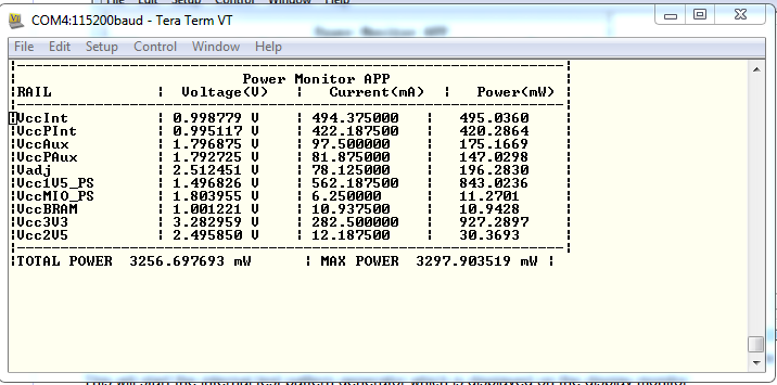
Figure 9: Change in Power when internal test pattern is generated
You will notice the average power of the VCCINT , VCCPINT and VCC1V5_PS has increased. - At the same time observe the HP Port 0 AXI bandwidth usage in the QT window.
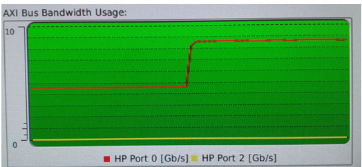
Figure 10. Change in HP Port 0 bandwidth indicating more activity on the Zynq PL.
This clearly indicates that by starting the internal test pattern generator, the amount of data being sent to the display controller operation has increased. This has increased the dynamic power consumption of the PL logic which has shown increased power consumption on the VCCINT rail.There has also been dynamic power consumption on the DDR Rails which has shown consumption on the VCC1V5_PS power supply. - On the Qt-based video GUI application, Change the Sobel Mode from OFF to SW.By doing this the Sobel Video processing (edge-detection filter) is done by software code which is running on the PS.
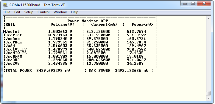
Figure 11: Increase in power due to Sobel Processing in Software
You will notice the average power of the VCCPINT has further increased ~420mW to ~540mW . - At the same time observe the CPU1 Usage in the QT window.
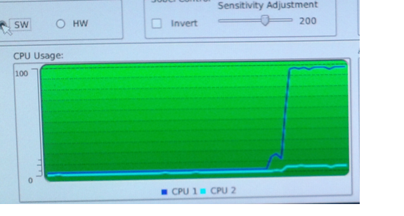
Figure 12. Increase in CPU utilization indicating cpu cycles being consumed to perform sobel filtering
This clearly indicates that by starting the starting Sobel Operation in, CPU1 is further spending efforts in performing the Sobel Operation in software which has increased the dynamic power consumption of processor by 100 mW. - On the Qt-based video GUI application, Change the Sobel Mode from SW to HW.
By doing this the Sobel Video processing (edge-detection filter) operation is offloaded from the CPU to the Sobel Filter Hardware implemented in the Programmable logic.So by theory you should see a reduction in the Processing System power, Increase in the Programmable Logic Power and also an increase in the DDR Controller Power.
As noticed in your serial terminal, the power consumption of the VCCPINT power reduced from ~540mW to 512 W.The power consumption of the VCCINT power has further increased ~506mW to ~630mW .
You will also notice the average power of the VCC1V5_PS which powers the DDR IOs and the DDR3 memories has PINT has further increased ~930mW to ~1150mW . - At the same time observe the CPU1 Usage and the AXI Bandwidth usage statistics which will explain the above power consumption results.

Figure 14. Decrease in CPU utilization and Increase in memory traffic observed.
Also observe while the power consumption went up when moving the Sobel Filter operation from PS to PL, we have seen that the performance has improved , and the performance per watt was dramatically increased.
6. Conclusion:
This tech tip has demonstrated on how to access the UCD9248 PM bus controllers available on the ZC702 board on a linux platform. The power monitor application demonstrates the required functions to convert voltages and current values provided in linear format to real world values.Using the Zynq Base TRD we were not only able to demonstrate the power consumption of the ZC702 board but also see the performance per watt improvement by offloading software intensive tasks from software to hardware. The same technique can also be applied to any other design to measure power consumption of each rail on the ZC702 board while the design is operating.
7. Appendix A: List of Components using the ZC702 power supplies.
The list of components powered by different power regulators on the ZC702 board is described in detail in the Appendix A: List of Components using the ZC702 power supplies section in the
Measuring ZC702 Power using TI Fusion Power Designer Tech Tip.
8. Appendix B: File Descriptions
- Zynq7000AP_SoC_ZC702_pwr_monitor_Linux _design\sd_card_ images
- Contains Zynq Base TRD sdcard images files.
- Zynq7000AP_SoC_ZC702_pwr_monitor_Linux _design \sw\srcs
- Contains source files for the Linux SDK project.
© Copyright 2019 - 2022 Xilinx Inc. Privacy Policy