Zynq-7000 AP SoC Spectrum Analyzer part 1 - Accelerating Software & More - Installing and Running the Spectrum Analyzer Demo Tech Tip
Table of Contents
Document History
| Date | Version | Author | Description of Revisions |
| April 30 2014 | 1.0 | Faster Technology | Initial posting |
| Date | Author | Comment | |
|---|---|---|---|
Description/Summary
A Single Chip Reference Design for Data Acquisition and DSP Signal Processing implementing a Spectrum Analyzer to demonstrate the capability of the Zynq-7000 AP SoC on the ZC702.
These instructions are for operating the demonstration design. No implementation is discussed in this Tech Tip. The implementation of the design is discussed in other Tech Tips.
Implementation
| Implementation Details | |
| Design Type | PS & PL |
| SW Type | Linux |
| CPUs | Both ARM processors at standard ZC702 frequencies |
| PS Features | Uses all standard PS features to run embedded Linux |
| PL Cores | Video processing cores, XADC support core, AXI interconnect, FFT core from core generator, AXI DMA core |
| Boards/Tools | ZC702 and XA-2 headphone input adapter from Faster Technology |
| Xilinx Tools Version | Built with Vivado / SDK 2013.4 and base TRD |
| Other Details | Requires standard ZC702 power supply and cables; an HDMI monitor supporting 1920 X 1080P is required for video output |
| Files Provided | |
| **ZC702FFTdemo.zip** | SD card image |
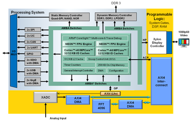
Block Diagram
Overview
Single Chip Reference Design for Data Acquisition and DSP Signal Processing
12 bit 1 Mega-sample Per Second Data Acquisition via Integrated XADC
– Low Latency Sample Delivery Directly via DMA to Processor Cache
FFT Function Acceleration vs ARM alone Demonstrated Via:
– ARM Cortex-A9 NEON Instructions or
– Programmable Logic Based Xilinx Complex FFT Core
Low Latency and High Performance Data Passing between Processor and Programmable Logic via Accelerator Coherency Port
Graphical display output via HDMI
Available as Reference Design from Xilinx
.
Expected Results
Accelerate FFT with NEON Instructions or
Via Programmable Logic Coprocessor
4096 point FFT – Complex 32 bit floating point
- ARM processor alone – 830 usec
- NEON SIMD engine – 571 usec
- Hardware in PL fabric – 129 usec
Setup and Operation
Download the referenced SD card image file: ZC702FFTdemo.zip
Requirements:
- ZC702
- Micro-USB to USB Hub Cable
- USB Hub
- USB Mouse (Keyboard is optional)
- 4GB or larger SD Card to hold design
- Optional to see boot process with USB-UART terminal
- USB to Mini-USB for USB UART
- PC
- TeraTerm or equivalent terminal
program installed on PC
- HDMI 1920 X 1080P display
- HDMI to HDMI cable
- Faster Technology XA-2 headphone adapter
- MP3 player / phone / tablet as signal source
- Headphone cable
Setup:
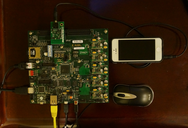
- Setup per Photo Below
- Not required but shown
- Ethernet
- Serial port (USB UART)
- Recommended but not shown
- USB power adaptor for MP3 player & speaker
- If used then USB hub not required
- Optional
- Keyboard w touchpad instead of mouse
- Speaker attached to splitter from MP3 player and power from USB hub
Operation:
- Connect cables per previous slide
- Create bootable SD card from card image zip file
- Download zip file from ZC702FFTdemo.zip
- Unzip image and copy files to blank SD card
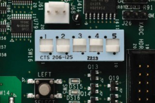
- Set ZC702 switches to boot from SD card slot
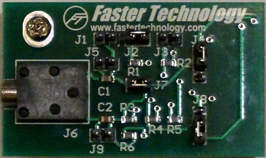
- Set up input source using Faster Technology XA-2 headphone adapter
- Verify that jumper settings are set to defaults
- J2 and J7 connected
- J4 2 & 3 connected
- J8 1 & 2 connected
- Insert XA-2 into XADC header
- Connect signal source (MP3 player, etc.) using standard 3.5 mm stereo cable as shown in setup photo
- Insert SD card into ZC702 and turn on power
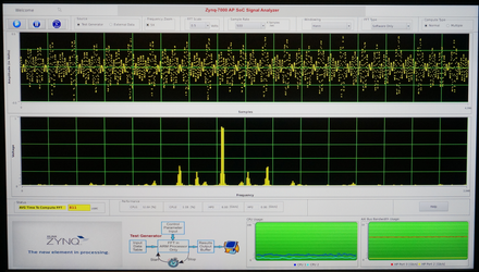
- Demo will begin self running with defaults
- Test Pattern Generator
- Normal FFT Display
- FFT Scale = 1 Volt Max
- Sample Rate = 1 Msps
- Hann Windowing
- SW FFT computation
- Normal compute
Controls:
Control Bar at top of display screen.
Operation of controls:
Play, Pause, Pause 5 seconds repeatedly
Click button o select Test Generator or External Data (XADC input)
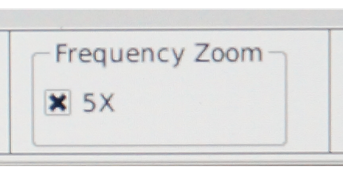
Click to select 5X zoom of Frequency display (horizontal zoom) - Good for display of low frequency sources
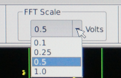
Select vertical scale (max value) FFT display - 0.1, 0.25, 0.5 or 1.0 volts - enhances low level signals
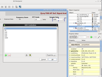
Sample Rate - select the XADC sample rate (20, 50, 100, 200 5001000 K Samples / sec.)
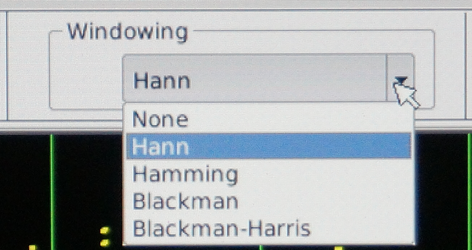
Windowing - select none or a common FFT window (http://en.wikipedia.org/wiki/Window_function)
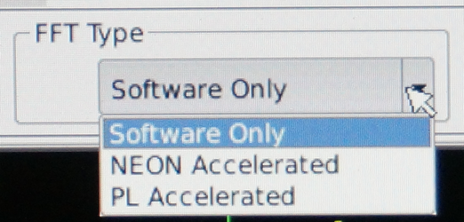
FFT Compute resource - Software, NEON, PL Accelerated (See yellow status window for average compute time)
Compute Type - Normal / Multiple - multiple reads and computes 1000 FFTs and then displays the last computed value. Useful for seeing relative update performance and CPU loading.
Information Displays:
Status Window - displays average compute time for the FFT - depends on FFT type selected.
Performance - shows the CPU loading and use of the HP ports between the PS and PL
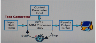
Block Diagram shows the data flow in the application - changes based on selected input and FFT type
Usage - graphically shows CPU and AXI bus loading
Conclusions:
This demonstration clearly shows the power of the Zynq 7000 AP Soc in action. Observers can see the FFT being performed and displayed and compare the different methods of performing the complex FFT calculations. The graphics are performed with the Qt system in conjunction with the hardware display controller used in the video base Targeted Reference Design, demonstrating the power of the Vivado / SDK development environment and compatibility with standard ARM / Linux system components that users might access in building their Zynq based systems.
– Test Pattern Generator
– Normal FFT display
– FFT Scale = 1 Volt Max
– Sample Rate = 1Msps
– Hann Windowing
– SW FFT
Normal compute
© Copyright 2019 - 2022 Xilinx Inc. Privacy Policy
