Zynq-7000 AP SoC SATA part 1 - Ready to Run Design Example Setup
Zynq-7000 AP SoC SATA part 1 – Ready to Run Design Example Setup
Zynq SATA Storage Extension
Table of Contents
For sales and technical support please visit us at:
http://MLEcorp.com/ZynqSSE
Block Diagram
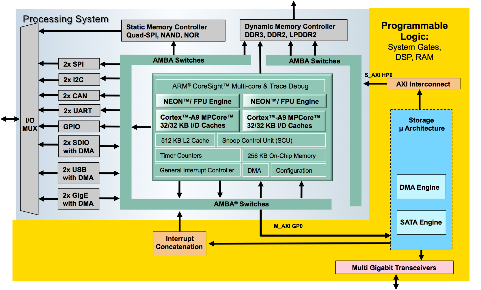
=The block diagram shown below gives an overview over the Zynq SSE reference design: Within the Zynq Programmable Logic (PL) the MLE storage micro-architecture instantiates the DMA and the SATA Host Controller IP blocks. The storage micro-architecture itself interfaces with the Zynq Processing System (PS) via the high-performance AXI HP0 slave port. The ARM A9 in the PS runs Xilinx PetaLinux and the SATA Linux kernel driver.Implementation
| Implementation Details |
|
| Design Type |
PS + PL |
| SW Type |
Linux (Petalinux) |
| CPUs |
2 CPUs 700 MHz |
| PS Features |
DDR, USB, UART, ETHERNET |
| PL Cores |
ASICS.WS SATA IP |
| Boards/Tools |
Avnet Mini ITX Z045 |
| Xilinx Tools Version |
Vivado 2014.1, PETALINUX 2013-2 |
| Other Details |
SATA SSD(including Cable and Power Supply), SD-Card |
| Address Map |
|||
| Base Address |
Size |
Interface |
|
| SATA IP |
0x41000000 |
4K |
S AXI |
| DMA IP |
0x41010000 |
4K |
S AXI, M AXI |
| Files Provided |
|
| SD Card Image |
All Files needed to run the ZYNQ SSE |
Step by Step Instructions
Hardware needed:- Avnet Mini ITX Z045 Board (including Power supply) Link
- Micro USB Cable for USB Console
- Supported SSD (for Example Samsung 840)
- Power Supply for SSD
- Micro SD Card (2 GB or bigger)
- PC for UART console
Software Assembly:
1. Format the SD Card using FAT32 File system
2. Put image.ub and BOOT.bin into the root directory of the SD Card
Hardware Assembly:
- Insert the SD Card into the Avnet Mini ITX board’s SD Slot
- Connect the micro USB cable to the UART port of the Avnet Mini ITX board and the USB Port of your PC
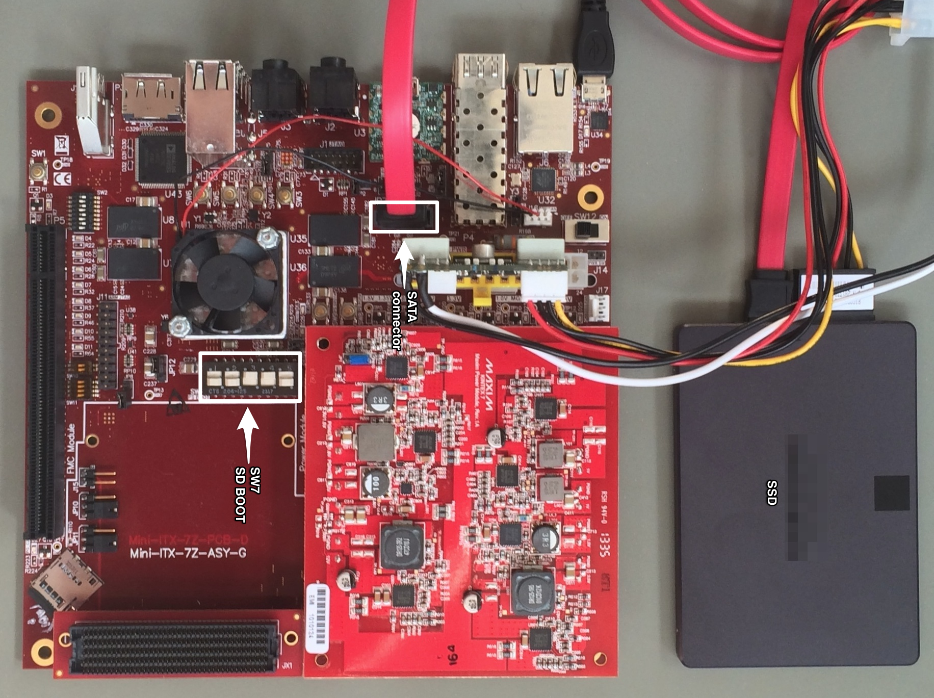
- Connect the SSD to the SATA connector on the Avnet Mini ITX board using the SATA Cable.
- Connect the SSD to power
- Switch the Avnet Mini ITX board’s SW7 to SD Boot mode (as shown in picture)
- Connect the Avnet Mini ITX board to the Power Supply
The system should now look like in the supplied image
Startup:
- Switch on the Avnet Mini ITX board
- On the PC open a Serial Terminal on the new serial port using the settings 115200 Baud 8N1
4. After some time you should see a screen similar to the screenshot in the Expected Results.
5. Login using
• Login:root
• Password: root
LED Description
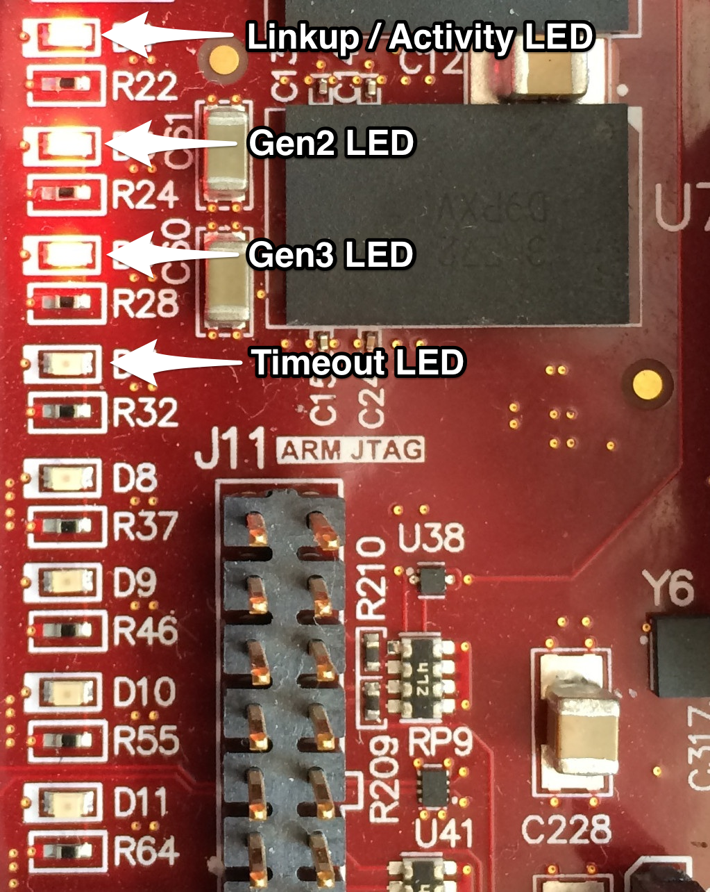
Status LEDs can be found next to the PCIe connector. The associated meanings can be seen in the following table and in the Image below.
Expected Results
As a result you should be having a running Linux system on the Zynq board. The UART Console output should be similar to the screenshot below.The Evaluation Reference Design (ERD) of the Zynq SSE comprises a hardware license management which allows to run full SATA functionality for up to 12 hours after power-up. After approximately 12 hours the evaluation expires, which is indicated by illuminating the LED ’timeout’. You will also notice that the Linux kernel driver informs you of having lost the SATA link to the SSD/HDD.
| D7 |
Timeout LED, indicates the Timeout of the IP core. |
| D6 |
Gen3 Link, indicates 6 GBit/s connection |
| D5 |
Gen2 Link, indicates 3 GBit/s connection |
| D4 |
Linkup and Activity, Led will light up on Linkup and will go dark during data transfers |
© Copyright 2019 - 2022 Xilinx Inc. Privacy Policy


