K7 Embedded TRD 2013.2
Table of Contents
1 Introduction
This page provides instructions on how to build various components of the Kintex-7 Embedded Targeted Reference Design (TRD) and how to setup the hardware platform and run the design on the Kintex-7 FPGA Embedded Kit. The Kintex-7 FPGA Embedded kit is based on a XC7K325T-2FFG900C device. For additional information, refer to UG913.1.1 About the Kintex-7 Embedded TRD
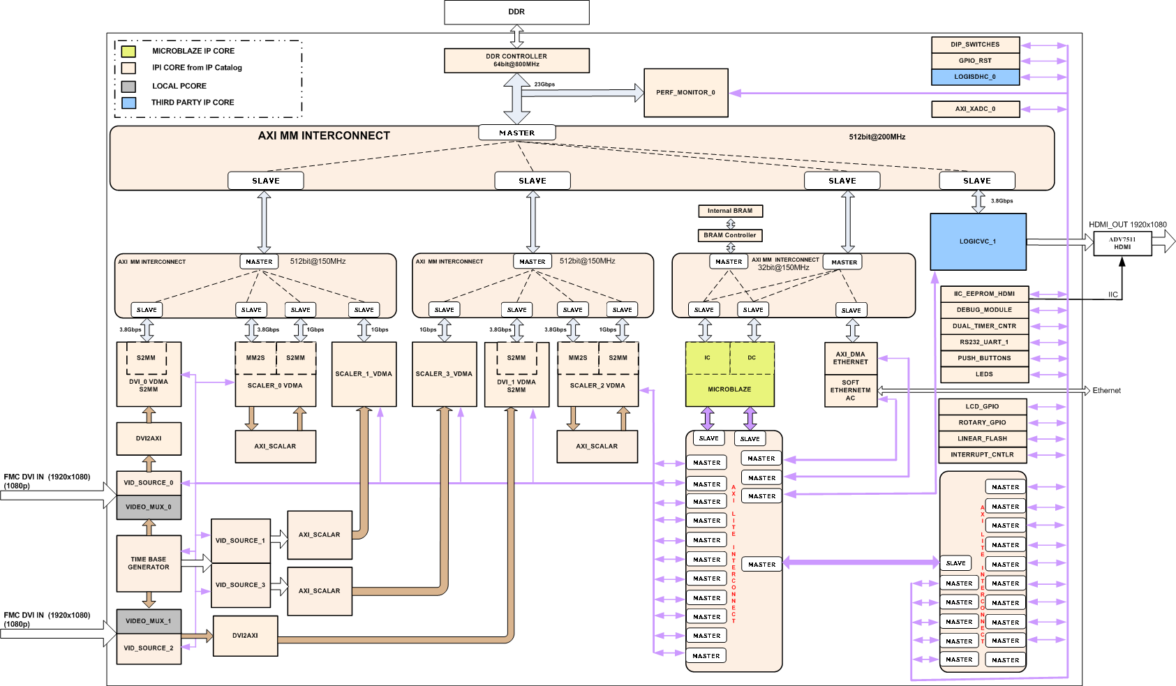
The Kintex-7 embedded TRD showcases various features of the KC705 evaluation board. The TRDs are built around a MicroBlaze soft processor with various peripherals to enable embedded applications. Two designs are provided as part of this TRD: the KC705 System (BIST system) and the Video Demonstration system. The BIST system provides a platform to jump-start embedded system development on the KC705 evaluation platform.The video demonstration is the superset of the BIST system. It provides a MicroBlaze processor based embedded platform which can be used to develop complex video systems. Along with these designs, a stand-alone software application and webserver-based application are provided. For additional information, please refer to UG985.
Block Diagram of KC705 (BIST) System

Block Diagram of Video Demonstration System
1.2 Kintex-7 Embedded TRD Package Contents
The Kintex-7 Embedded TRD package is released with the source code, Xilinx Vivado and SDK projects. The package also contains a stand-alone software application and webserver-based application which enables the user to run both the designs. This wiki page assumes the user has already downloaded the Kintex-7 Embedded TRD package and extracted its contents to the K7 TRD home directory referred to as K7_TRD_HOME in this wiki page.Note: Because the package has a deep hierarchy structure, unzip the package at a user location so that the overall path length is smaller.

2 Prerequisites
- The KC705 Embedded Kit ships with the version 2013.x Device-locked for the XC7K325T-2FFG900C FPGA and all required licenses to build the TRD. For additional information, refer to UG973, Vivado Design Suite User Guide: Release Notes, Installation, and Licensing
- KC705 embedded kit MicroBlaze processor subsystem
- Proper hardware setup and software installation, as described in UG913, Getting Started with the Kintex-7 FPGA KC705 Embedded Kit
- EDK, SDK User Guide documents
- General knowledge of FPGAs, digital design concepts, and microprocessors
- Basic familiarity with the Xilinx Design Tools
- Basic VHDL/Verilog knowledge
3 Building the FPGA Hardware Bitstream and Exporting the Hardware Platform to SDK
This section explains how to generate the FPGA hardware bitsream using the Xilinx Vivado tool and how to export the hardware platform to Xilinx Software Development Kit (SDK) for software application development.3.1 BIST System
A pre-compiled bitstream can be found at $K7_TRD_HOME/ready_to_test/k7_emb_bist_top.bit.
Steps for building the BIST System FPGA hardware bitstream and Exporting the Hardware Platform to SDK
On Windows 7 platform:
- Open Vivado 2013.x Tcl Shell by clicking Start > All Programs > Xilinx Design Tools > Vivado 2013.x > Vivado 2013.x Tcl Shell
- Navigate to $K7_TRD_HOME/hardware/vivado/runs/ in the Vivado 2013.x Tcl Shell window.
- Type launch_run.bat bist in the Tcl Shell Window and press enter.
On Linux platform:
- Set VIVADO tool version to 2013.2
- Navigate to $K7_TRD_HOME/hardware/vivado/runs/
- Type ./launch_run.sh bist at the command prompt and press enter.
In launch_run script an automated TCL script will be called which will launch VIVADO, creates k7_emb_bist project and constructs a block diagram.
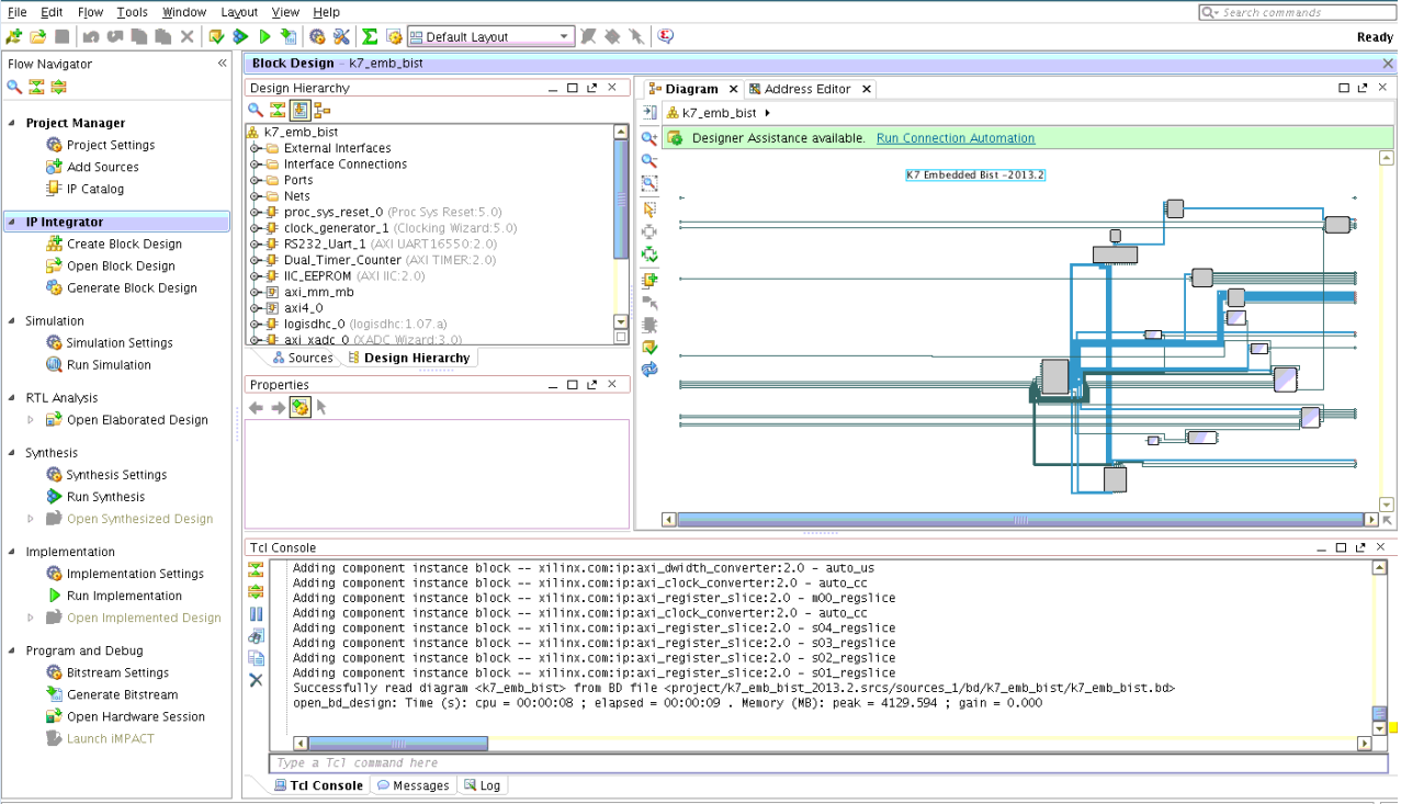
In the Flow Navigator pane on the left-hand side under Program and Debug, click Generate Bitstream. The bitstream will be generated at $K7_TRD_HOME/hardware/vivado/runs/k7_emb_bist/project/project.runs/impl_1/k7_emb_bist_top.bit
In the flow navigator click on Open Implemented Design. Click on "OK" when prompted for no trace timing results were found.. message
From the menu bar, select File > Export > Export Hardware.
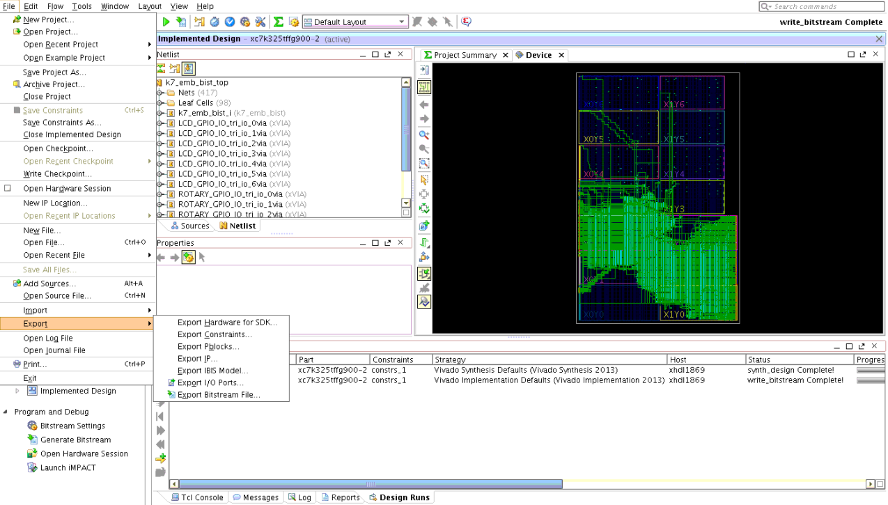
In the Export Hardware window press OK. The SDK hardware platform will be exported to $K7_TRD_HOME/hardware/vivado/runs/k7_emb_bist/project/project.sdk/SDK/SDK_Export

3.2 Video Demonstration System
A pre-compiled bitstream can be found at $K7_TRD_HOME/ready_to_test/k7_emb_vdemo_top.bitSteps for building the Video Demonstration System FPGA hardware bitstream and Exporting the Hardware Platform to SDK
Once you execute launch_run command, given below, it will take approximately 5 hours to complete this step.
On Windows 7 platform:
- Open Vivado 2013.x Tcl Shell by clicking Start > All Programs > Xilinx Design Tools > Vivado 2013.x > Vivado 2013.x Tcl Shell
- Browse to $K7_TRD_HOME/hardware/vivado/runs/ in the Vivado 2013.x Tcl Shell window.
- Type launch_run.bat vdemo in the Tcl Shell Window and press enter.
On Linux platform:
- Browse to $K7_TRD_HOME/hardware/vivado/runs/
- Type ./launch_run.sh vdemo at the command prompt and press enter.
In launch_run script an automated TCL script will be called which will launch VIVADO, creates k7_emb_vdemo project and constructs a block diagram.
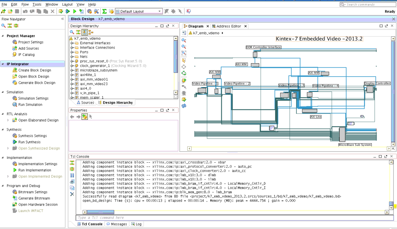
In the Flow Navigator pane on the left-hand side under Program and Debug, click Generate Bitstream. The bitstream will be generated at
$K7_TRD_HOME/hardware/vivado/runs/k7_emb_vdemo/project/project.runs/impl_1/k7_emb_vdemo_top.bit
In the flow navigator click on Open Implemented Design. Click on "OK" when prompted for no trace timing results were found.. message
From the menu bar, select File > Export > Export Hardware.

In the Export Hardware window press OK. The SDK hardware platform will be exported to
$K7_TRD_HOME/hardware/vivado/runs/k7_emb_vdemo/project/project.sdk/SDK/SDK_Export

Note: If the Launch SDK option is checked in the Export Hardware window, SDK will be launched immediately after SDK export has completed. This is not recommended at this point
4. Building Software Applications
The software applications described in this tutorial are:- Hello World application
- Board Test Apps (Console mode) application
- Board Test Apps (Webserver mode) application
- Video Demonstration application
Steps involved in building a Software Application:
- Create a workspace using SDK tool
- Import a Hardware platform
- Create / Import BSP (board support package); modify settings as needed
- Create / Import software application; modify settings as needed
- Build the application
Types of Board Support Packages:
Different software platforms can be used to cover a variety of different needs. These platforms include:
- Stand-alone platforms for small dedicated systems that do not require an OS
- Xilkernel (kernel for Xilinx embedded processors) for small systems that need to manage multiple tasks
- Linux for systems that have large software content (not part of this TRD).
Based on the platform, software application development is divided into two primary categories:
• Application development based on a stand-alone environment.
• Application development based on the xilkernel OS environment.
Prebuilt applications and platforms are available in the Kintex-7 Embedded TRD package as a reference at $K7_TRD_HOME/software
4.1 Application development based on a stand-alone environment
Steps listed below are followed for stand-alone software development:
• Create a new workspace and import the hardware platform into the workspace
• Create a new board support package (BSP) and application
• Import an existing BSP and software application into a workspace
4.1.1 Create a new workspace and import the hardware platform into the workspace
To begin working with SDK, an SDK workspace must be created. An SDK workspace is a directory that contains information on the projects being worked on. The workspace holds software project files, SDK settings, and log files.
The hardware platform is the embedded hardware design that is exported in the form of an XML file. The hardware platform is populated to SDK when the XML file is imported. Multiple hardware platform projects can be created in SDK.
Note:
- The hardware platform project used build standalone application is the hardware specification exported from the hardware system which is located at $K7_TRD_HOME/hardware/vivado/runs/k7_emb_bist/project/project.sdk/SDK/SDK_Export/hw
- Alternately, the prebuilt xml file for BIST system is placed at location: $K7_TRD_HOME/software/standalone_app/board_test_app/hw_platform
The process of creating a new SDK workspace and importing a hardware platform into the workspace includes:
• Creating a New SDK Workspace for Software Development
• Adding a New Hardware Platform Project to an SDK Workspace
Creating a New SDK Workspace for Software Development
- Launch SDK.
- On Windows, select Start > All Programs > Xilinx Design Tools > Vivado 2013.x > SDK > Xilinx SDK 2013.x
- On a Linux host, enter xsdk at a command prompt.

3. When SDK opens, a Welcome screen is displayed. Close the Welcome screen after browsing through the displayed information. When the Welcome screen is closed, the Project Explorer tab is displayed and is empty.
Adding a New Hardware Platform Project to an SDK Workspace
To develop applications with SDK, a hardware platform must be specified in the SDK workspace. To add a hardware platform project into the workspace, follow these steps:1. Select File > New > Project... > Xilinx > Hardware Platform Specification in SDK.
2. Populate the new hardware platform project with these selections:
• Project Name: hw_platform
• Project Location: Ensure that the Use default location checkbox is selected.
• Target Hardware Specification: Click Browse and select hardware design export file (.xml) from one of the above paths.
3. Click Finish.

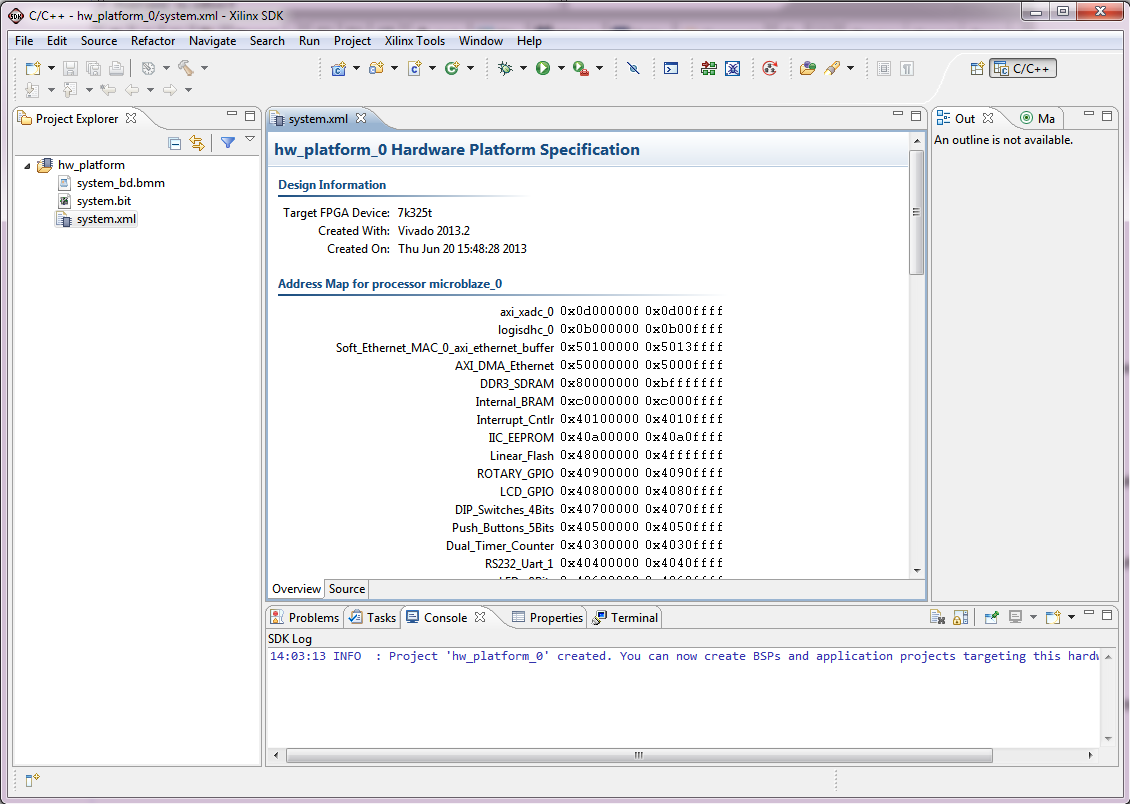
4. When the hardware platform is loaded, the Project Explorer tab includes the hardware platform. The system XML file in this view provides a short summary of the hardware platform when opened in SDK.
4.1.2. Create a new board support package (BSP) and application
After the SDK workspace is created and the hardware platform is imported, a new BSP can be created in the SDK. A BSP contains libraries and drivers that software applications can utilize when using the provided APIs. A software project is the software application source and settings.
This section uses a Hello World software application as an example of creating a new stand-alone software project. The Hello World software project is created from one of the example application templates provided in the SDK. The process of creating a Hello World software project with a new BSP using the stand-alone software platform includes:
• Creating the Hello World Software Project and BSP
• Running the Hello World Software Project
Creating the Hello World Software Project and BSP
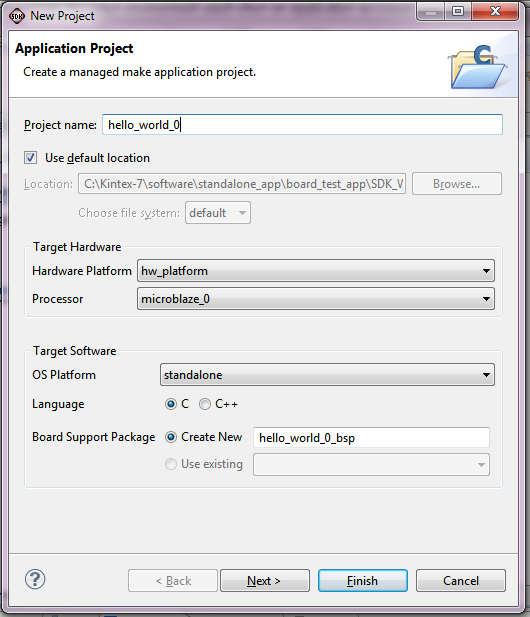
Follow these steps to create the Hello World application project and a corresponding BSP. The BSP is built to use the stand-alone software platform. Although this BSP is created for use with a Hello World software application, it can be used for other software applications that require a basic stand-alone software platform.1. Select File > New > Application Project in the SDK.
2. Enter the Project Name: as hello_world_0.
3. Keep Use default location selected.
4. Keep the default selections for Target Hardware.
5. Keep the OS Platform selection at Standalone, Language selection to C. For Board Support Package select Create New. This selection creates a new BSP for the Hello World software application project. The default name for BSP is populated with hello_world_0_bsp.
6. Click Next.
7. Select the template for Hello World.
8. Click Finish. The SDK starts to compile the hello_world_bsp_0 BSP and the hello_world_0 application.
Note: For Xilinx C projects, SDK automatically create makefiles which compile the sources into object files and link the object files into an executable file.
View / Modify BSP settings:
1. Right-click hello_world_0_bsp in the Project Explorer tab and select Board Support Package Settings. Settings for the BSP can be changed in these menus.
2. The BSP settings menu is popped up, and the Overview menu is the initial menu shown. This initial menu contains the OS type and version used, as well as a description of the selected OS type. This menu shows the target hardware specification file location and the target processor. This menu also allows the option to add libraries, such as the Xilinx Flash library and the lwip TCP/IP Stack library. No special settings are needed in this initial screen.
3. Select the stand-alone menu. This menu includes the configuration options for the stand-alone software platform.
4. In the Operating System configuration section of the stand-alone menu, ensure that stdin and stdout are set to rs232_uart_1 by clicking the text in the Value column.
5. Select the drivers menu. In this menu, the driver and driver version used for the hardware platform peripherals can be viewed. No special settings are needed in the drivers menu.
6. Select the cpu menu. This menu includes processor driver parameters that can be changed, including the compiler that is used for libraries and applications, and any extra compiler flags that are needed for compilation. No special settings are needed in the cpu menu.
7. Click OK. The BSP and application are recompiled.
After the hello_world_bsp_0 BSP and hello_world_0 applications are compiled, expand the microblaze_0 section of hello_world_bsp_0 in the Project Explorer tab. The code, include, lib, and libsrc folders contain the libraries for the hardware peripherals in the reference system. In this view, files can be opened by double-clicking them.
Now expand the src section of hello_world_0 in the Project Explorer tab. The source code of the Hello World application project is stored here.
Double-click the helloworld.c file. The file opens in the SDK Editor window. The file can be modified as needed.
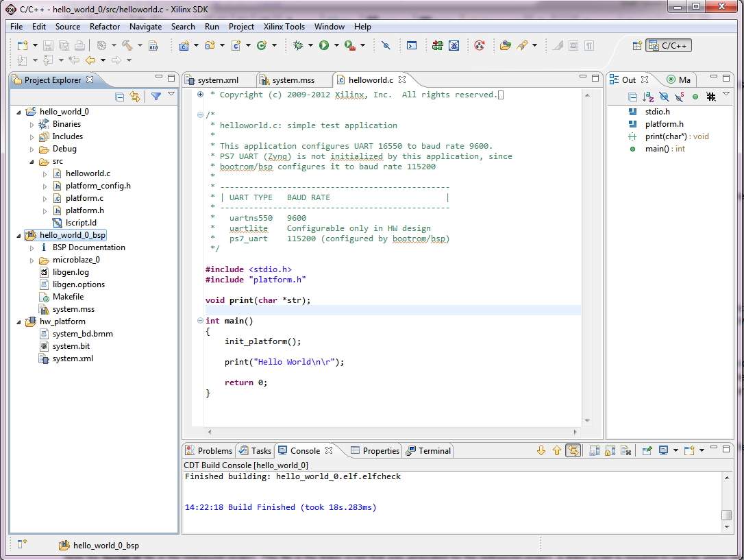
Note the lscript.ld file in the helloworld project. This file is the linker script that was generated for the helloworld project. A linker script is required to specify where the software code is loaded in the hardware system memory.
Running the Hello World Software Project
After the Hello World application is created and built, it can be run on the KC705 board. Follow these steps to program the FPGA and run the Hello World application:
Note: Ensure that the Kintex-7 board is connected to Host PC, as detailed in the Getting Started Guide
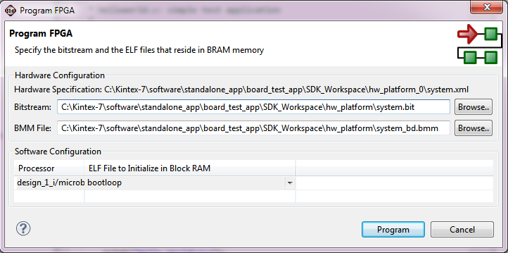
1. The FPGA must be programmed with the hardware configuration bitstream before the software application can be run. Program the FPGA with these steps:
a. In the SDK, select Xilinx Tools > Program FPGA.
b. Ensure that the system.bit and system_bd.bmm files are selected from $K7_TRD_HOME/software/standalone_app/board_test_app/SDK_Workspace/hw_platform/. Leave the initialization ELF as bootloop. Bootloop keeps the processor in a known state while it waits for another program to be downloaded to run or to be debugged.
c. Click Program to program the FPGA. SDK confirms when the FPGA is successfully programmed with the bitstream.
2. SDK provides two build configurations: Debug and Release.
Each build configuration uses a different set of compiler settings, macros, and linker settings.
This application uses the Release configuration to run without debugging. Right-click the hello_world_0 application in the Project Explorer tab and select Build Configurations > Set Active > Release. The hello_world_0 application is rebuilt for the Release configuration.
3. In the Project Explorer tab, right-click hello_world_0 and select Run As > Run Configurations.
4. In the Run Configurations box, select Xilinx C/C++ ELF and click the New button to create a new Run configuration.
5. Populate the Main tab of the new run configuration with these selections:
• Name: hello_world_0 Release
• C/C++ Application: Release/hello_world_0.elf
• Project: hello_world_0
• Build Configuration: Release
6. Click the STDIO Connection tab and click the Connect STDIO to Console checkbox to enable the STDIO of the program to go to the SDK Console window. Set the COM port as appropriate for the host computer, and leave the BAUD rate at 9600.
7. Click Run. An XMD console appears which shows the hello_world_0 application being downloaded into memory and run.
8. The hello_world_0 application displays Hello World on the SDK Console.

4.1.3 Import an existing BSP and software application into a workspace (board_test_app_Console)
This exercise shows how to import the existing BSP and application provided with the embedded kit reference system into the SDK instead of creating a new BSP or application. This readily available application comes up with a menu appearing in the UART console. The user can select the test applications in the console by entering the test number and pressing Enter to run the test on target. The KC705 board runs the selected test. The results of the tests are displayed on the console. It is a simple design to start with. The BSP called board_test_app_console_platform is provided for the application built in console app.This section describes the board_test_app_Console design flow. In this exercise, we use the SDK workspace created in above section. The design flow for the board test software application (console app) includes:
• Importing the Board Test Software Application and BSP,
• Board Test BSP Settings,
• Running the Board Test Software Application,
• Tests in the Board Test Application,
Importing the Board Test Software Application and BSP (Console App)
The SDK can import existing SDK projects into an SDK workspace. The application (board_test_app_Console) and BSP (board_test_app_Console_platform) are imported into the SDK workspace by following these steps:1. In the SDK, select File > Import > General > Existing Projects into Workspace > Next.
3. To specify the root directory from which software projects are to be imported, click Browse... and specify the location where the software projects are stored. For this reference system, the board_test_app_Console and
board_test_app_Console_platform project are stored under $K7_TRD_HOME/software/standalone_app/board_test_app.This directory should be specified as the root directory.
4. Ensure that the board_test_app_Console and board_test_app_Console_platform projects are selected.
If the hello_world section is completed, the hw_platform project showed in grey color and cannot be selected.
If the hello_world section is not completed, select the hw_platform project also in the Import wizard.
Note: The hardware platform project (hw_platform) used for board_test_app_Console is the same as the hardware platform project created in previous section (hello_world)
5. Select the Copy projects into workspace check box to make a local copy of the projects in the workspace when the import is done.
6. Click Finish. SDK imports the selected projects. The BSP and software application are compiled during the import process.

When a BSP is imported into a workspace, the SDK looks for a hardware platform project in the workspace, that is associated with that BSP project.
When a software application is imported into a workspace, the SDK looks for a hardware platform project and a BSP in the workspace, that are associated with that Application project.
7. After the application and platform are imported and compiled, they appear in the Project Explorer tab.
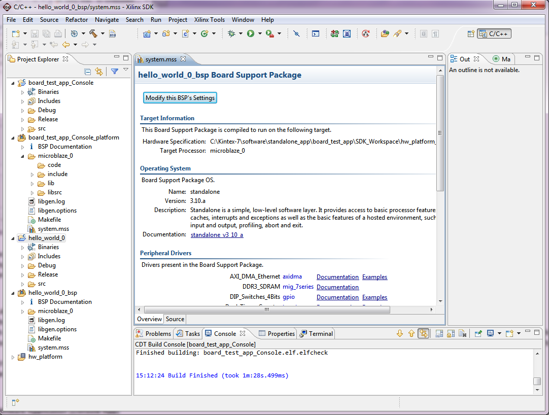
Board Test BSP (Console App) Settings
The board_test_app_Console_platform (BSP) settings are modified to suite for the board_test_app_Console application. The changes are:1. Right-click board_test_app_Console_platform and select Board Support Package Settings.
Under the Overview > Supported Libraries, select xilflash library.
The xilflash library provides read, write, erase, lock, and unlock functionality to access a parallel flash device.
3. Click OK.
4. This rebuilds the BSP and application.
Running the Board Test Software Application (Console App)
After the board test application and platform are imported and built, the application can be run on the KC705 board. Follow these steps to set up the serial terminal console, program the FPGA, and run the board test application:1. The FPGA programming is done as described in section: Running the Hello World Software Project.
2. Set the configuration to Release, as described in section: Running the Hello World Software Project.
3. Start Run Configurations, as described in section: Running the Hello World Software Project.
Select files as below:
- Name: board_test_app_Console Release
- Project: board_test_app_Console
- C/C++ Application: Release/board_test_app_Console.elf
5. Click Run. The board_test_app_Console application displays the test menu to the terminal screen.
Tests in the Board Test Application (Console App)
This section describes the tests included in the board test application. These tests are not extensive tests. They exercise the basic functionality of the hardware peripherals in the embedded kit reference system. Below Table describes the tests available in the board_test_app_console application.| Menu Selection | Test | Description |
| 1 | UART test | Prints Hello World! to the terminal. |
| 2 | LED test | Flashes the LEDs on the board. |
| 3 | IIC test | Uses IIC to write to the EEPROM, read the data back, and compare the data. |
| 4 | Flash test | Tests flash memory by erasing a block in flash memory, writing to that block, reading the data back, and comparing the data. Uses the xilflash library. |
| 5 | Timer test | Initializes a timer counter and allows it to expire and generate an interrupt. |
| 6 | Rotary test | Rotary switch that supports detection of left turns, right turns and switch press is tested. |
| 7 | Switch test | Reads the value of the switches and prints out the ON/ OFF state of each switch. |
| 8 | SD Card test | Writing and reading blocks from the Secure Digital High Capacity (SDHC) card is tested. The hardware and software driver IPs are provided by Xylon. Note: Back up the SD card content before this test because this test overwrites a few blocks on the SD card. |
| 9 | LCD test | Displays a message on the LCD. The LCD supports 2 lines with 16 characters per line. |
| A | XADC test | Reads current on-chip temperature and on-chip voltages (VCCINT and VCCAUX). |
| B | Button test | Recognizes each push button press. |
| C | Ethernet loopback test | Sets the Ethernet PHY to loopback mode and sends and receives a single frame. |
| D | External memory test (minimal) | Writes and reads test patterns to a small chunk of memory in the DDR3 SDRAM. |
| E | External memory test (complete) | Writes and reads test patterns to complete memory in the DDR3 SDRAM. This test takes a few minutes to complete. |
| F | Block RAM memory test | Writes and reads test patterns to internal block RAM memory. |
| 0 | Exit | Exits the board test application. |
4.2 Application development based on the Xilkernel OS environment
For this part of tutorial, the workspace of previous sections can be used.
However, for simplicity and better understanding, we recommend to use a new workkspace: C:\Kintex-7\software\xilkernel_app\SDK_Workspace
Secondly, the hardware platform used for the board_test_app_Webserver application is same as the one used for board_test_app_Console application.
However, we demonstrated the import of all projects including the hardware platform as well.
The KC705 Embedded Kit has two applications, board_test_app_Webserver and video_demo_app, based on Xilkernel OS.
4.2.1 Import an existing BSP and software application into a workspace (board_test_app_Webserver)
The board_test_app_Webserver application for KC705 system is built on:- Xilkernel OS
- Light weight IP (lwip) stack
- Xilmfs (memory file system)
The target supports Webserver and is configured with a static IP address. When the host computer is connected to the KC705 target with an Ethernet cable and browsed with the static IP address, a Web page appears on the host computer with the board test applications menu. The user can select the test applications in the Web page by clicking various radio buttons to run the selected test on the target. The KC705 board runs the selected test, posts the results of the board test to the host computer, and the results are displayed in the Web page.
- Create a new workspace. Specify the SDK workspace path as C:\Kintex-7\software\xilkernel_app\SDK_Workspace in the Workspace Launcher
- Click OK.
- Copy the $K7_TRD_HOME/software/xilkernel_app/board_test_app/memfs folder into the workspace folder: C:\Kintex-7\software\xilkernel_app\SDK_Workspace
- Click on File > Import > General > Existing Projects into Workspace > Browse
- Import the board_test_app_Webserver project from: $K7_TRD_HOME/software/xilkernel_app/board_test_app
- Select board_test_app_Webserver, board_test_app_Webserver_platform and hw_platform projects.
- select Copy projects into workspace.
- Click Finish.
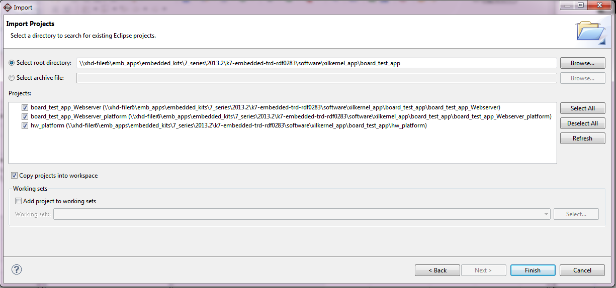
The BSP and Application are imported and the executable is created.

The BSP settings for Xilkernel application are modified to suite the requirements of the board_test_app_Webserver.
The changes can be observer by right click on board_test_app_Webserver_platform and select Board Support Package Settings.
Before Running the Board Test Software Application (Webserver App)
Before executing the application, the user needs to set up the Ethernet connection on the host computer, so that the Web server can execute. The KC705 board is configured to the static IP address of 192.168.1.10.
1. Connect the KC705 board and host computer with an Ethernet cable.
2. On the host computer, set the Ethernet IP address to the static address as follows:
a. Click Start > Control Panel > Network Connections > Local Area Connection.
b. In the General tab, select Internet Protocol (TCP/IP) and click Properties.
c. Select Use the following IP address.
d. Enter this address in IP address area: 192.168.1.xxx (exampled: 192.168.1.00)
e. Enter this address in Subnet mask area: 255.255.255.0.
f. Click OK.
Running the Board Test Software Application (Webserver App)
After the board test application and platform are imported and built, the application can be run on the KC705 board. Follow these steps to set up the serial terminal console and Web browser, program the FPGA, and run the board test application:
1. The FPGA programming is done as described in section: Running the Hello World Software Project
2. Set the Build Configuration to Release, as done in section: Running the Hello World Software Project
3. Start Run configuration and select the project files as listed here:
• Name: board_test_app_Webserver Release
• Project: board_test_app_Webserver
• C/C++ Application: Release/board_test_app_Webserver.elf
4. Set the STDIO settings as done in section: Running the Hello World Software Project.
5. Click Run.
The board_test_app_webserver application displays messages on the terminal screen.
1. Wait till the last message auto-negotiated link speed: 1000 appears. Now the Web server is ready to load the content.
2. On the host computer, start the Web browser (Internet Explorer version 8 or 9) and type http://192.168.1.10 in the address bar, and Click Go.
3. The Web server loads the content from target to the host computer. It contains the menu options for board test apps and a console screen.
4.2.2 Building Video Demonstration with xilkernel and lwip
The KC705 embedded kit provides a video demonstration that leverages Xilinx IPs capabilities (such as VDMA) and demonstrates the benchmarking of AXI-MM.The steps for building the video demonstration are summarized here and are explained in detail in the rest of this section.
1. Creating a New SDK Workspace for the Video Demonstration
Includes steps on how to create a new SDK workspace for the benchmarking demonstration. All other sections on the video demonstration use the SDK workspace created in this section.
2. Adding a Local Repository
Describes the steps necessary to add a local repository to the SDK workspace. This is required because the video demonstration uses Xylon IP core for display engine (CVC) and Xilinx xilmfs drivers with additional utilities.
3. Importing the Hardware Platform Project, Video Demonstration Application, and BSP
Details how to import the provided video demonstration projects into an SDK workspace.
4. Video Demonstration BSP
Describes the BSP for the video demonstration software.
5. Video Demonstration Application
Describes the video demonstration software application.
6. Video Demonstration Hardware Setup
Details the hardware setup requirements to run the video demonstration.
7. Running the Video Demonstration
Includes steps on how to run the video demonstration using the SDK.
8. Interacting with the Video Demonstration
Describes the user interface for the video demonstration.
Creating a New SDK Workspace for the Video Demonstration
To avoid confusion with the files for stand-alone software development, this section assumes that a new SDK workspace is used for the benchmarking demonstration files. To perform other steps completion of this step is essential.
Follow below steps to create a new SDK workspace
1. Launch SDK, and create new workspace
2. Specify the SDK workspace path:: C:\Kintex-7\software\xilkernel_app\video_demo\SDK_Workspace
3. Click OK in the Workspace Launcher.
Copy these two folders into the workspace area: C:\Kintex-7\software\xilkernel_app\video_demo\SDK_Workspace
- $K7_TRD_HOME/software/xilkernel_app/video_demo_app/memfs
- $K7_TRD_HOME/software/xilkernel_app/video_demo_app/repository
The hardware platform for the video demonstration uses two local drivers:
• The xilmfs core supports additional utilities for MFS.
• The logiCVC core is third party IP core (logiCVC) from Xylon that supports the video display engine. The video demonstration software application uses a software driver (from the same vendor) corresponding to the logiCVC to access the logiCVC core.
These two drivers are stored in a local repository. The location of that repository must be added to the SDK workspace as follows:
1. In the SDK, select Xilinx Tools > Repositories.
2. Click New... by the Local Repositories box.
3. Browse to C:\Kintex-7\software\xilkernel_app\video_demo\SDK_Workspace\repository and click OK to add the directory as a repository.
4. Click OK to complete the selection.
Importing the Hardware Platform Project, Video Demonstration Application, and BSP
The hardware platform project, video demonstration application, and related BSP are provided with the embedded kit.
Import the hardware platform project (hw_platform), video demonstration application (Video_Demo) and platform (xilkernel_bsp_0) into the SDK workspace as follows:
1. Importing the video_demo project is similar to importing the board_test_app_Console project described in above section.
2. Click on File > Import > General > Existing Projects into Workspace. To specify the root directory, click Browse... and select $K7_TRD_HOME/software/xilkernel_app/video_demo_app.
3. Select the Copy projects into workspace check box to make a local copy of the projects in the workspace when the import is done. When a BSP is imported into a workspace, the SDK looks for a hardware platform project in the system. When a software application is imported into a workspace, the SDK looks for a hardware platform project and a BSP in the workspace. This is why the video_demo project must be imported into the SDK workspace at the same time as the xilkernel_bsp_0 BSP and hw_platform project.
4. Click Finish. SDK imports the selected projects. The BSP and software application are compiled during the import process.
Video Demonstration BSP
The BSP for the video demonstration uses xilkernel. Xilkernel is a simple and lightweight kernel that provides services such as scheduling, threads, synchronization, and timers. Xilkernel requires a timer and the benchmarking demonstration hardware platform includes the AXI_Timer peripheral to suit this purpose.The BSP also includes the lwip TCP/IP stack library. The Web server portion of the video demonstration application code uses the lwip socket API.
The Xilinx memory file system (xilmfs) library is included in the BSP. This library is used to store files in the memory of the KC705 board that can be accessed by the Web server.
The third party libraries for logiCVC and xyl_oslib (from Xylon) are also included in the BSP. These two libraries support the driver functionality of the logiCVC display IP core. The logiCVC carries out actual driver functionality of the logiCVC IP core, and xyl_oslib contain the OS wrappers that are needed by the logiCVC driver. To view the BSP settings, right-click xilkernel_bsp_0 and select Board Support Package Settings. After browsing the settings, click Cancel to exit the Software Platform Settings.
Video Demonstration Application
The video demonstration application uses a Web server to display the video selection menu, video stream controls, and plot various graphs such as throughput data, on-chip temperature, and on-chip voltages (VCCINT and VCCAUX). The Web server uses the lwip socket API.
For GET requests, the Web server looks for the requested file on the memory file system and if present, the file is sent to the Web browser making the request. If the file is not present on the memory file system, an HTTP 404 error page is sent to the browser. Contents of the memory file system for the benchmarking demonstration can be viewed in $K7_TRD_HOME/software/xilkernel_app/video_demo_app/memfs/memfs_files.
On the Web server, after the video streams are selected, the selected video streams start to display on the monitor. Also, the performance monitor periodically collects the performance numbers.
The AXI-MM throughput data for read and write and other on-chip parameters are requested by means of the POST request. When AXI-MM throughput data is requested by the Web server, the software application posts the current read and write performance throughput numbers that are probed at the AXI-MM interface. The video streams are continuously performing the frame buffer transactions by means of various VDMA channels. Hence the performance numbers reflect the traffic at the AXI-MM interface. Then, the video_demo application sends the throughput number (in Gb/s) and the appropriate HTTP header to the requesting Web browser.
Video Demonstration Hardware Setup
The video demonstration uses a Web server to serve a Web page that graphs the AXI-MM data throughput and on-chip parameters (temperature, VCCINT, and VCCAUX).The video demonstration setup has two variants:
• With external (live) video
• Without external (live) video
The hardware setup for video demonstration is done as described in UG913, Getting Started with the Kintex-7 FPGA KC705 Embedded Kit.
Running the Video Demonstration
After the video demonstration files are imported and built, the application can be run on the KC705 board. Follow these steps to set up the serial terminal console, program the FPGA, and run the video demonstration:1. Program the FPGA as described in Running the Board Test Software Application (console app), section 4.1.3. Ensure that the bitstream from $K7_TRD_HOME/software/xilkernel_app/video_demo_app\SDK_Workspace\hw_platform\is used.
2. Right-click video_demo and select Run As > Run Configurations.
3. In the Run configurations box, select Xilinx C/C++ ELF and click the New button icon to create a new Run configuration.
4. Populate the Main tab of the new debug configuration with these selections:
• Name: video_demo Release
• Build Configuration: Release
• Project: video_demo
• C/C++ Application: Release/video_demo.elf to select the executable that was built with the Release configuration
5. Set the STDIO settings as done in Running the Hello World Software Project, section 4.1.2.
6. Click Run. An XMD console appears indicating that the Video_Demo application is downloaded into memory and run.
The Video_Demo application displays information about the Web server on the terminal screen, as described in UG913, Getting Started with the Kintex-7 FPGA KC705 Embedded Kit.
Interacting with the Video Demonstration
When the Web server is running, the Web browser on the connected host computer displays the video demonstration Web page when the URL is set to http://192.168.1.10. The Web page uses JavaScript, so the browser must have JavaScript enabled.The execution of video demonstration and the selection of various options are described in UG913, Getting Started with the Kintex-7 FPGA KC705 Embedded Kit in detail. However, a quick start for the video demonstration is as follows.
On a Web page, perform the following:
• Click the NO radio button under LIVE VIDEO.
• Click the All Scaled streams radio button under STREAM SELECTION.
• Click the Move around checkbox under PATTERN SELECTION.
These settings start all 4 streams in scaled mode and also apply the move around feature. The monitor starts to display the streams and graphs on the Web page start being plotted. The Web browser receives one packet of results at a time. This packet contain 5 results:
• Read throughput (Gb/s)
• Write throughput (Gb/s)
• On-chip temperature (degrees Celsius)
• On-chip VCCINT voltage
• On-chip VCCAUX voltage
The graphs update every time a new data packet is received. After the graph completely shifts to left side, the oldest data point is dropped and the newest data point is added. This application continues to run infinitely. To terminate the test, close the Web page and turn off the board.
© Copyright 2019 - 2022 Xilinx Inc. Privacy Policy