Zynq UltraScale MPSoC Base TRD 2016.3
This wiki page complements the 2016.3 version of the Base TRD. For other versions, refer to the Zynq UltraScale+ MPSoC Base TRD overview page.
Note: The ES1 reference design zip file is no longer available for download. Please update to ES2 or production silicon.
Table of Contents
1 Revision History
Change Log:
- Update all projects, IP and tools versions to 2016.3
- Add support for ZCU102 rev 1.0 board with ES2 silicon
- Split reference design into 9 design modules with dedicated tutorials
- Remove support for HDMI input via FMC-HDMI-CAM
- Add USB webcam support for video capture (USB2 only!)
- Add virtual video device (vivid) support for video capture
- Use X11 Qt and Mali backend instead of fbdev
2 Overview
The Zynq UltraScale+ MPSoC Base Targeted Reference Design (TRD) is an embedded video processing application running on a combination of APU (SMP Linux), RPU (bare-metal) and PL.
The design consists of the following video data paths:
- Video capture pipelines capturing video from:
- a virtual video device (vivid) implemented purely in software
- a USB webcam connected to the PS (optional)
- a test pattern generator (TPG) implemented inside the PL
- A memory-to-memory processing pipeline implementing a 2D-convolution filter with programmable coefficients.
- A display pipeline with two layers, one used for video and the other for a graphical user interface (GUI) rendered by the GPU.
The TRD demonstrates the value of offloading computation intensive tasks like the 2D-convolution filter from the PS onto PL, thereby freeing APU resources. The APU load is plotted on the GUI to compare a pure software vs hardware accelerated implementation. The RPU is used to monitor the live memory throughput of the design by reading the built-in AXI performance monitors (APM) inside the PS. The data is sent to the APU via the OpenAMP communication framework and plotted on the GUI.
This wiki contains information about:
- How to setup the ZCU102 evaluation board and run the reference design.
- How to build all the TRD components based on the provided source files via detailed step-by-step tutorials.
Additional material that is not hosted on the wiki:
- User Guide containing information about system, software and hardware architecture.
- Reference Design Zip File for ZCU102 rev 1.0 / ES2 silicon including all source code and project files.
- Reference Design Zip File for ZCU102 rev D / ES1 silicon including all source code and project files.
- Third Party Library Sources for separately licensed material that is not included in the reference design.
Note: Certain material in this reference design is separately licensed by third parties and may be subject to the GNU General Public License version 2, the GNU Lesser General License version 2.1, or other licenses.
3 Software Tools and System Requirements
3.1 Hardware
Required:
- ZCU102 evaluation board / power cable
- Monitor with DisplayPort input supporting one of the following resolutions:
- 3840x2160 or
- 1920x1080 or
- 1280x720
- Display Port cable (DP certified)
- USB hub with mouse and keyboard
- SD card
Optional:
- USB webcam
3.2 Software Tools
Required:
- Linux host machine for all tool flow tutorials (see here for detailed OS requirements)
- SDSoC Development Environment version 2016.3
- Xilinx Software Development Kit (XSDK) version 2016.3
- PetaLinux Tools version 2016.3
- Git distributed version control system
- GNU make utility version 3.81 or higher
Optional:
- Silicon Labs quad CP210x USB-to-UART bridge driver
- Serial terminal emulator e.g. teraterm
3.3 Licensing
The video Test Pattern Generator IP inside the Vivado project requires a license which can be obtained from here.
Steps to generate the license:
- Click on the link mentioned above.
- Fill in the login details and proceed.
- Click on “Generate Node-Locked License" icon as shown in the picture:
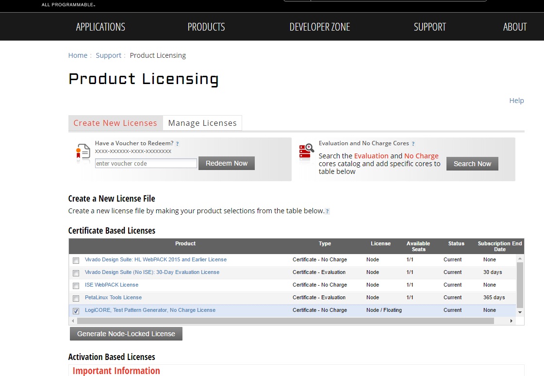
- Under system information, give the host details.
- Proceed until you get the license agreement and accept it.
- The License (.lic file) will be sent to the email-id mentioned in the login details.
- Copy the license file locally and give the same path in the SDSOC license manager.
3.4 Compatibility
The reference design has been tested successfully with the following user-supplied components.
DisplayPort Monitor:
| Make/Model | Native Resolution |
| Viewsonic VP2780-4K | 3840x2160 (30Hz) |
| LG 27MU67-B | 3840x2160 (30Hz) |
| Acer S277HK | 3840x2160 (30Hz) |
| Dell U2414H | 1920x1080 (60Hz) |
| GeChic On-Lap1303H | 1920x1080 (60Hz) |
DisplayPort Cable:
- Cable Matters DisplayPort Cable-E342987
- Monster Advanced DisplayPort Cable-E194698
USB Webcam:
| Make/Model | Supported Resolutions | Supported Formats |
| Logitech HD Pro Webcam C920 | 1920x1080 (5fps), 1280x720 (10fps) | YUYV |
| Logitech HD Webcam C525 | 1920x1080 (5fps), 1280x720 (10fps) | YUYV |
4 Design Files
The top-level directory structure is shown in the figure below.

4.1 Design Modules
The reference design is split into 9 design modules DM1 to DM9:
- DM1 – APU SMP Linux
- DM2 – RPU0 FreeRTOS Application
- DM3 – RPU1 Bare-metal Application
- DM4 – APU/RPU1 Inter Process Communication
- DM5 – APU Qt Application
- DM6 – PL Video Capture
- DM7 – OpenCV-based Image Processing
- DM8 – PL-accelerated Image Processing
- DM9 – Full-fledged Base TRD
Each module is described in more detail in UG1221 and on the respective tutorial page.
The following table shows the dependency matrix between different modules. For example: DM6 (row) depends on or builds on top of modules DM1 and DM5 (columns).
| DM1 | DM2 | DM3 | DM4 | DM5 | DM6 | DM7 | DM8 | |
| DM1 | ||||||||
| DM2 | ||||||||
| DM3 | ||||||||
| DM4 | + | + | ||||||
| DM5 | + | |||||||
| DM6 | + | + | ||||||
| DM7 | + | + | + | |||||
| DM8 | + | + | + | + | ||||
| DM9 | + | + | + | + | + | + | + | + |
4.2 Design Components
The below figure shows the relevant design components for DM9 as well as inter-dependencies and generated output products.
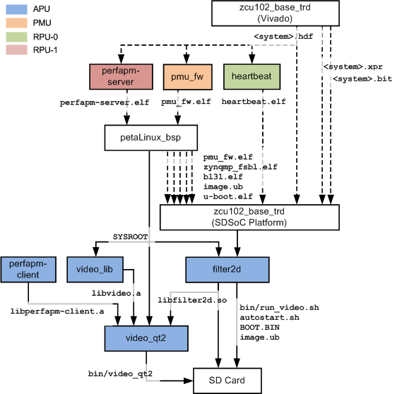
The below table shows which design components are used in which design modules. A graphical view for each design module is provided on the respective design module tutorial page.
| Design Component | Design Module | ||||||||
| DM1 | DM2 | DM3 | DM4 | DM5 | DM6 | DM7 | DM8 | DM9 | |
| apu/perfapm-client/perfapm-client | Y | Y | |||||||
| apu/perfapm-client/perfapm-client-test | Y | ||||||||
| apu/petalinux_bsp | Y | Y | Y | Y | Y | Y | Y | ||
| apu/videao_app/video_lib | Y | Y | Y | Y | Y | ||||
| apu/videao_app/video_qt2 | Y | Y | Y | Y | Y | ||||
| apu/zcu102_base_trd/samples/filter2d | Y | Y | Y | ||||||
| pl/zcu102_base_trd | Y | ||||||||
| pl/zcu102_dp_only | Y | ||||||||
| pmu/pmu_fw | Y | Y | Y | Y | Y | Y | Y | Y | Y |
| rpu0/heartbeat | Y | Y | |||||||
| rpu1/perfapm-server/perfapm | Y | Y | Y | ||||||
| rpu1/perfapm-server/perfapm-ctl | Y | ||||||||
| rpu1/perfapm-server/perfapm-server | Y | Y | |||||||
5 Tutorials
5.1 Board Setup
Required:
- Connect power supply to J52.
- Connect USB mouse and keyboard using a USB hub to J83.
- Connect DisplayPort cable to P11; connect other end to monitor.
- Insert SD card (FAT formatted) with binaries copied from $TRD_HOME/images/dm9 directory.
- Connect micro-USB cable to J83 USB UART connector; use the following settings for your terminal emulator:
- Baud Rate: 115200
- Data: 8 bit
- Parity: None
- Stop: 1 bit
- Flow Control: None
Optional:
- Connect USB webcam to a USB hub to J83.
Jumpers & Switches:
- Set boot mode according to your board and silicon revision
- For rev D with ES1 silicon: SW6[4:1] - on,off,on,off
- For rev 1.0 with ES2 silicon: SW6[4:1] - off,off,off,on
- Configure USB 2.0 jumpers for host mode
- J110: 2-3
- J109: 1-2
- J112: 2-3
- J7: 1-2
- J113: 1-2

To run the prebuilt SD card image for design module 9, follow the instructions here .
5.2 Build and Run Flow
The following tutorials assume that the $TRD_HOME environment variable has been set as below.
For rev 1.0 / ES2:
% export TRD_HOME=</path/to/downloaded/zip-file>/rdf0421-zcu102-base-trd-2016-3
% export TRD_HOME=</path/to/downloaded/zip-file>/zcu102-base-trd-2016-3
For some modules, the $PETALINUX environment variables needs to be set as well. This is done automatically when you source the PetaLinux settings.sh script (see PetaLinux installation guide).
For the individual tutorials, follow the links below:
- DM1 Tutorial – APU SMP Linux
- DM2 Tutorial – RPU0 FreeRTOS Application
- DM3 Tutorial – RPU1 Bare-metal Application
- DM4 Tutorial – APU/RPU1 Inter Process Communication
- DM5 Tutorial – APU Qt Application
- DM6 Tutorial – PL Video Capture
- DM7 Tutorial – OpenCV-based Image Processing
- DM8 Tutorial – PL-accelerated Image Processing
- DM9 Tutorial – Full-fledged Base TRD
6 Other Information
6.1 Known Issues
- The board doesn't boot and the INIT_B LED stays red.
- Frequency: Rare
- Workaround: Power cycle the board
- SDSoC accelerator code runs very slow in pure software implementation when Debug configuration is used
- Frequency: Always
- Workaround: Set project build configurations to Release which sets sdsoc compiler to optimize most (-O3)
- Linux 'reboot' command not working
- Frequency: Always
- Workaround: Power cycle the board
- At 1080p and 720p resolutions, the mouse cursor disappears when moved too far to the right and/or bottom of the screen
- Frequency: Always
- Workaround: Move mouse toward left and/or top until the cursor reappers on the screen
- PetaLinux prints the following warning message: WARNING: Failed to pack PMUFW, pre-built PMUFW doesnt exist. See help to load custom pmufw
- Frequency: Always
- Workaround: Message can be ignored
- Video capture cannot be started in GUI for native display of 1280x720 or 1920x1080 in auto-detection mode
- Frequency: Always
- Workaround: Edit the file autostart.sh and modify the arguments for the desired target resolution, e.g. for 1920x1080 change line
video_qt2_wrap.sh &
to
video_qt2_wrap.sh -r 1920x1080 &
or close the application and restart with command
run_video.sh -r 1920x1080
6.2 Limitations
- The application only supports the following display resolutions: 3840x2160p30, 1920x1080p60, and 1280x720p60.
- The application does not support audio.
- Only USB2.0 webcams are supported at this point.
- Make sure the DisplayPort cable is plugged in when you power on the board, otherwise the framebuffer console will default to 1024x768 resolution and the application will not start.
- DP-to-HDMI adapters are not supported, see AR 67462
7 Support
To obtain technical support for this reference design, go to the:
- Xilinx Answers Database to locate answers to known issues
- Xilinx Community Forums to ask questions or discuss technical details and issues. Please make sure to browse the existing topics first before filing a new topic. If you do file a new topic, make sure it is filed in the sub-forum that best describes your issue or question e.g. Embedded Linux for any Linux related questions. Please include "ZCU102 Base TRD" and the release version in the topic name along with a brief summary of the issue.
© Copyright 2019 - 2022 Xilinx Inc. Privacy Policy