Zynq Base TRD 2014.4
Zynq Base TRD 2014.4
Table of Contents
Vivado 2014.2 Targeted Base Reference Design
Vivado 2013.4 Targeted Base Reference Design
Vivado 2013.3 Targeted Base Reference Design
Vivado 2013.2 Targeted Base Reference Design
ISE DS 14.5 Targeted Base Reference Design
ISE DS 14.4 Targeted Base Reference Design
ISE DS 14.3 Targeted Base Reference Design
ISE DS 14.2 Targeted Base Reference Design
ISE DS 14.1 Targeted Base Reference Design
1 Introduction
This page provides instructions on how to build various components of the Zynq Base Targeted Reference Design (TRD) and how to setup the hardware platform and run the design on the ZC702 Evaluation Kit. The ZC702 Evaluation kit is based on a XC7Z020 CLG484-1 Zynq-7000 SoC device.
1.1 About the Base TRD
The Base TRD is an embedded video processing application designed to showcase various features and capabilities of the Zynq Z-7020 SoC device for the embedded domain. The Base TRD consists of two elements: The Zynq-7000 SoC Processing System (PS) and a video processing pipeline implemented in Programmable Logic (PL). The SoC allows the user to implement a video processing algorithm that performs edge detection on an image (Sobel filter) either as a software program running on the Zynq-7000 SoC based PS or as a hardware accelerator inside the SoC based PL. The Base TRD demonstrates how the user can seamlessly switch between a software or a hardware implementation and evaluate the cost and benefit of each implementation. The TRD also demonstrates the value of offloading computation-intensive tasks onto PL, thereby freeing the CPU resources to be available for user-specific applications. For additional , please refer to UG925: Zynq-7000 SoC: ZC702 Base Targeted Reference Design User Guide.1.2 Download the TRD
An archive with the TRD files can be downloaded here .1.3 Base TRD Package Contents
The Zynq Base TRD package is released with the source code, Xilinx Vivado and SDK projects, and an SD card image that enables the user to run the video demonstration and software application. It also includes the binaries necessary to configure and boot the Zynq-7000 SoC board. This wiki page assumes the user has already downloaded the Base TRD package and extracted its contents to the Base TRD home directory referred to as ZYNQ_TRD_HOME in this wiki.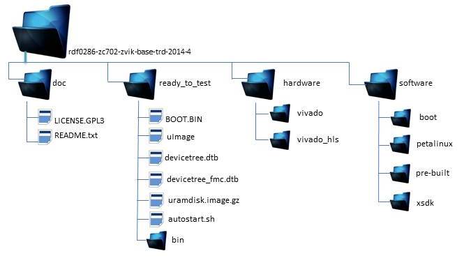
1.4 Prerequisites
- The ZC702 Evaluation Kit ships with the Xilinx Vivado™ Design Suite Device-locked to the Zynq-7000 XC7Z020 CLG484-1 device and all required licenses to build the TRD. For additional information, refer to Vivado Design Suite User Guide. A 30-day evaluation license can be generated after registering a Xilinx account.
- Xilinx IP evaluation licenses for the Video Timing Controller core can be ordered online.
- Xilinx PetaLinux tools version 2014.4
- Xylon logiCVC-ML is shipped as evaluation IP core that does not require a license. License options are listed on the Xylon logiCVC-ML product site.
- A Linux development PC with the ARM GNU tools installed.
- A Linux development PC with the distributed version control system Git installed. For information, refer to the Xilinx Git wiki and to UG821: Xilinx Zynq-7000 SoC Software Developers Guide.
- A Linux development PC with QT and QWT libraries cross-compiled for Zynq platform. Set ZYNQ_QT_INSTALL environment variable by referring to Xilinx Zynq Qt/Qwt Libraries - Build Instructions
- GNU make utility version 3.81 or higher.
1.5 Known Issues
- Test Pattern Generator (TPG) version 5 is used instead of version 6 (latest) to avoid TPG going out of frame boundary when video source is changed. In TPG selection, when the bouncing box touches the boundary of the monitor a horizontal line appears on the monitor.
- Occasionally on some hardware set-ups ADV7611 I2C slave returns NACK for I2C transaction. <adv7611 12-004c: not an adv7611 on address 0x98>.The workaround is to reboot the system.
- HDMI input is not working. The PG signal does not assert by default on early ZC702 boards. To be FMC compliant, the PG signal must be asserted when power rails are good. See AR51438 for solution.
2 Run the TRD demo
This section provides step by step instructions on how to bring up the ZC702 board for video demonstration part of the TRD and running different video demonstrations
out of the box.
The ZC702 Evaluation Kit comes with an SD-MMC card pre-loaded with binaries that enable the user to run the video demonstration and software applications.
It also includes the binaries necessary to configure and boot the Zynq-7000 SoC based ZC702 board.
Note:
a) If the evaluation kit design files were downloaded online, copy the entire folder content from $ZYNQ_TRD_HOME/ready_to_test onto the primary partition of the SD-MMC card which is formatted as FAT32 using a SD-MMC card reader.
b) Petalinux console login details:-
User : root
Password : root
c) In case user has optional FPGA Mezzanine Card (FMC) setup
ready_to_test/devicetree_fmc.dtb is renamed to devicetree.dtb and copy it to primary partition of SD-MMC card along with
- BOOT.BIN
- autostart.sh
- devicetree.dtb
- uImage
- uramdisk.image.gz
- bin/ __
- |- run_video.sh
- |- video_cmd
- |- video_qt
2.1 Hardware Setup Requirements
Requirements for TRD Linux application demo setup
- The ZC702 evaluation board with the XC7Z020 CLG484-1 part
- AC power adapter (12 VDC)
- Optional: An USB Type-A to USB Mini-B cable (for UART communications) and a Tera Term Pro (or similar) UART terminal program.
- USB-UART drivers from Silicon Labs
- A HDMI cable.
- Optional: FMC (FPGA Mezzanine Card).
- Optional: External Video Source e.g. Roku HD Streaming player.
- A SD-MMC flash card containing TRD binaries formatted with FAT32. The SD-MMC is pre-loaded with required binaries in its first partition. The pre-loaded binaries include :
- BOOT.BIN
- uImage
- devicetree.dtb
- devicetree_fmc.dtb
- uramdisk.image.gz
- autostart.sh
- bin/ __
- |- run_video.sh
- |- video_cmd
- |- video_qt
- An USB Micro-B to female Adaptor with USB hub is needed for connecting a keyboard and a mouse.
- An USB mouse and keyboard.
- A display monitor that supports HD resolutions: 1920 x 1080p @ 60 Hz, and 1280 x 720 @ 60 Hz(if the user also want to validate TRD with 720p video output)
Note:
It is recommended to use ZC702 production board.
TRD binaries has been tested with a Asus VS228 display monitor. However, the examples should work well with any HDMI-compatible output device provided it supports 720/1080p resolution in its EDID database.
2.2 Board Setup
Steps for setting the board
Connect the cables as shown in figure below to prepare the ZC702 board to run the TRD video demo applications.
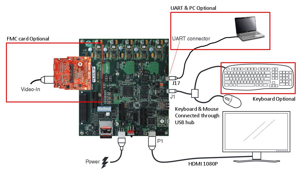
- Optional: Connect the HDMI FMC card (BD-FMC-IMAGEON-G).
- Connect a display monitor to the HDMI out port of the ZC702 board using a HDMI cable.
- Connect a keyboard and mouse to an USB hub, which is connected to the ZC702 board Micro-B USB connector. (Keyboard is optional if just using the mouse in the Qt GUI)
- Optional: Connect an USB Mini-B cable into the Mini USB port J17 labeled USB UART on the ZC702 board and the USB Type-A cable end into an open USB port on the host PC for UART communications.
- Connect the power supply to the ZC702 board. Do not switch the power on.
- Insert a SD-MMC memory card, which contains the TRD binaries, into the SD slot on the ZC702 board.
- Make sure the switches are set as shown in figure below, which allows the ZC702 board to boot from the SD-MMC card.
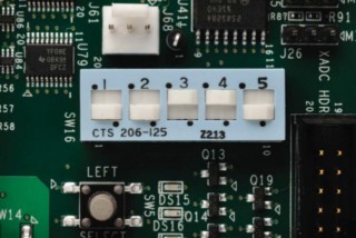
Note: The older ZC702 rev.x version boards does not have switches and contains jumpers. Use the following jumper settings: J21: 2-3, J20: 2-3, J22: 1-2, J25: 1-2, J26: 2-3
2.3 Run Qt GUI Application in 1080p mode
A Linux application with Qt-based GUI is provided with the package included on the SD-MMC memory card. This application provides options to user to exercise different modes of the video demonstration. The Qt application can be used in minimize / maximize mode. User can select Test Pattern Generator (TPG) video or External video source (requires the HDMI FMC card and an external video source). The transparency slider is provided to control the GUI transparency.
User can select to process a sobel filter (run as software code on the Zynq PS ) or in hardware (run in the FPGA fabric as a hardware IP core).
User can configure sobel filter controls i.e. Set sobel filter in invert/non-invert mode and control sobel sensitivity using sensitivity slider on QT GUI.
Powering on the Qt-based GUI application demo
- Make sure the monitor is set for HDMI or DVI 1920x1080 resolution. (Typically if a monitor has an HDMI input port, it will auto select for 1080P.@60Hz If it does not, then sometimes the video displayed will be odd)
- Turn on power switch SW11.
- The Linux image will load and be frame buffer console is displayed on the HDMI 1080P monitor.
- The Linux Qt based GUI will load
Running the Qt-based GUI application demo
- When the GUI starts up, you will see that there is no video pattern or external video being processed. You will see that the the CPU graph trace is at a low level of video processing activity. The AXI bus HP port 0 is utilized around 1Gb/s which is just passing the GUI data, but not processing any video data out the HDMI port. The AXI bus Port 1 is also not active, as this is the port that will interface to the FPGA fabric, and at this time there is not activity on this AXI bus.
- The user can click Help for short messages and information about the control window of the QT application.
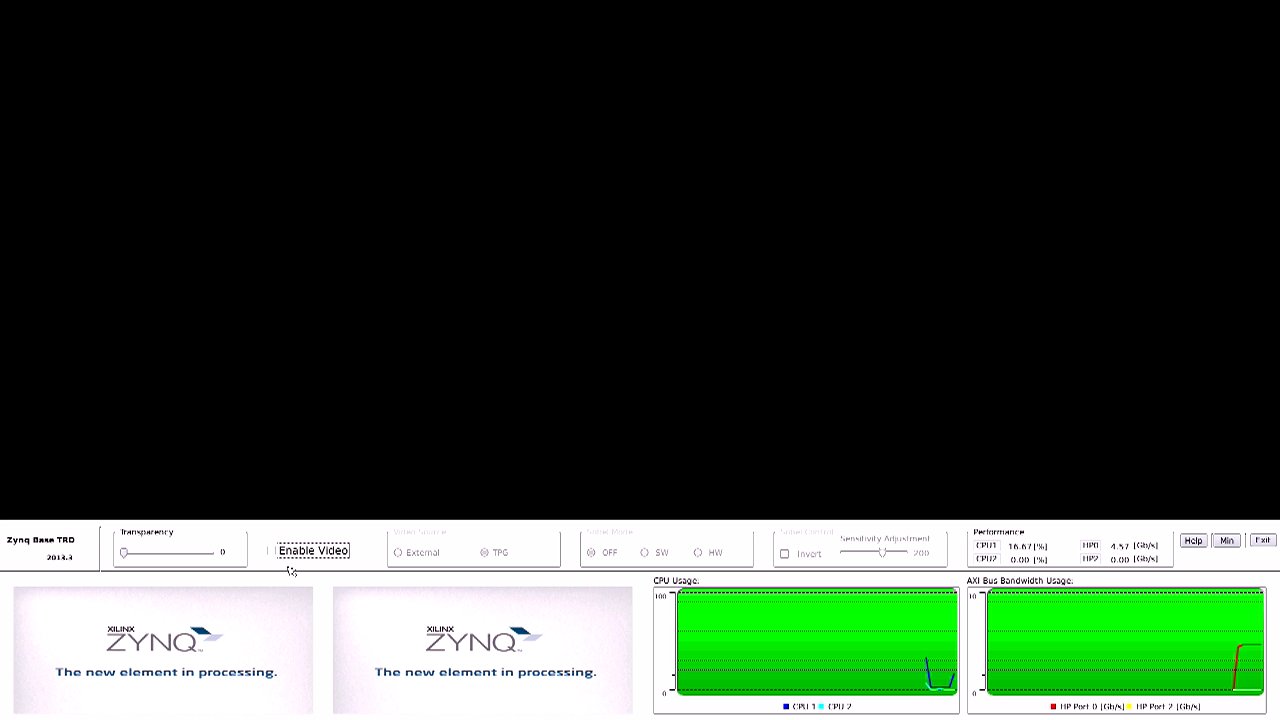
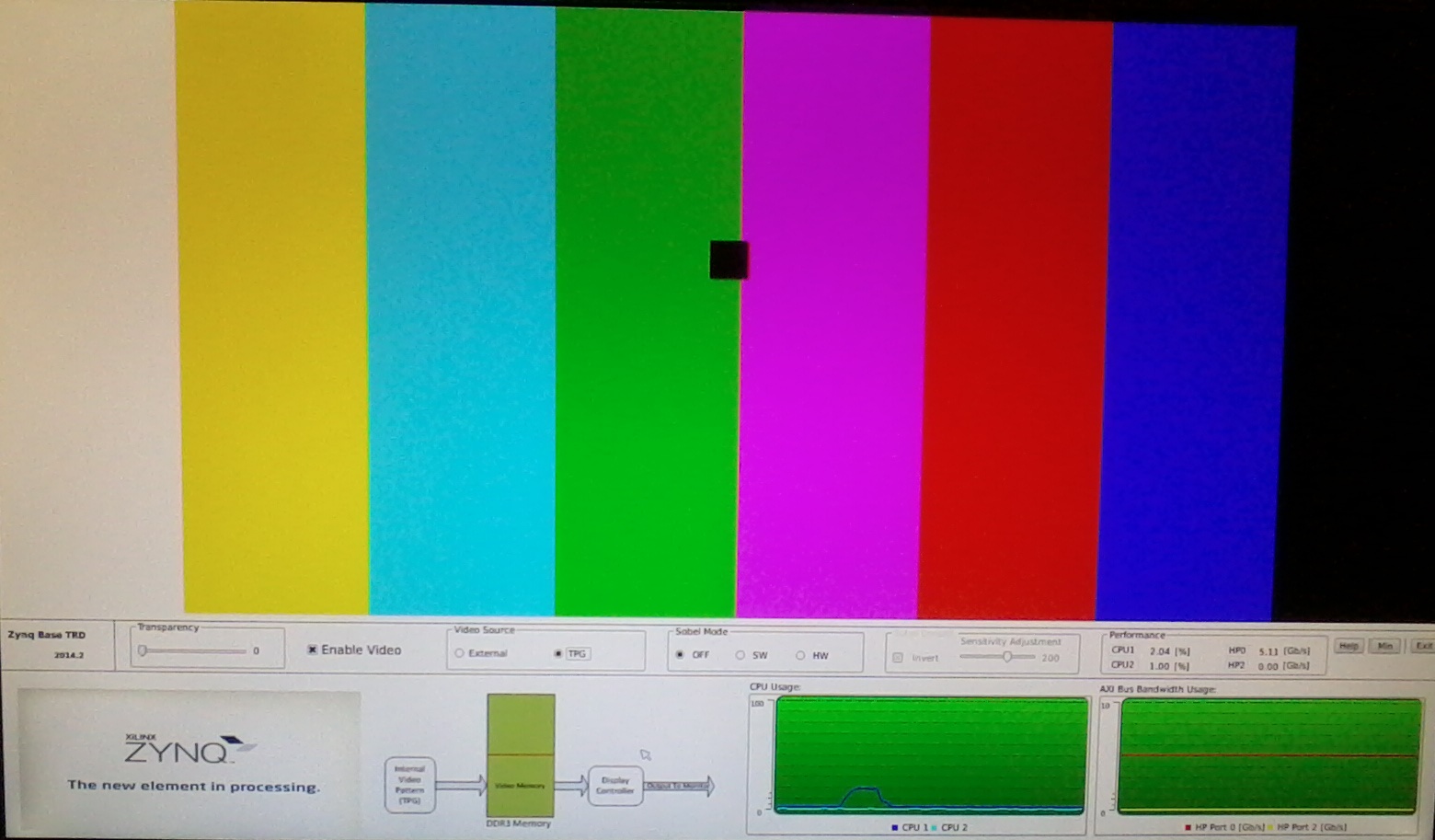
- Click the Enable Video check box. After enabling video , user will see that the GUI starts to display a locally generated test pattern with a moving box around the screen. User will not see much change in the CPU graph trace, and there is not a lot of processing over head to do this pass through of the video test pattern. Level of activity on the AXI bus HP port 0 jumps up, as more data is being passed out the HDMI AXI bus port.
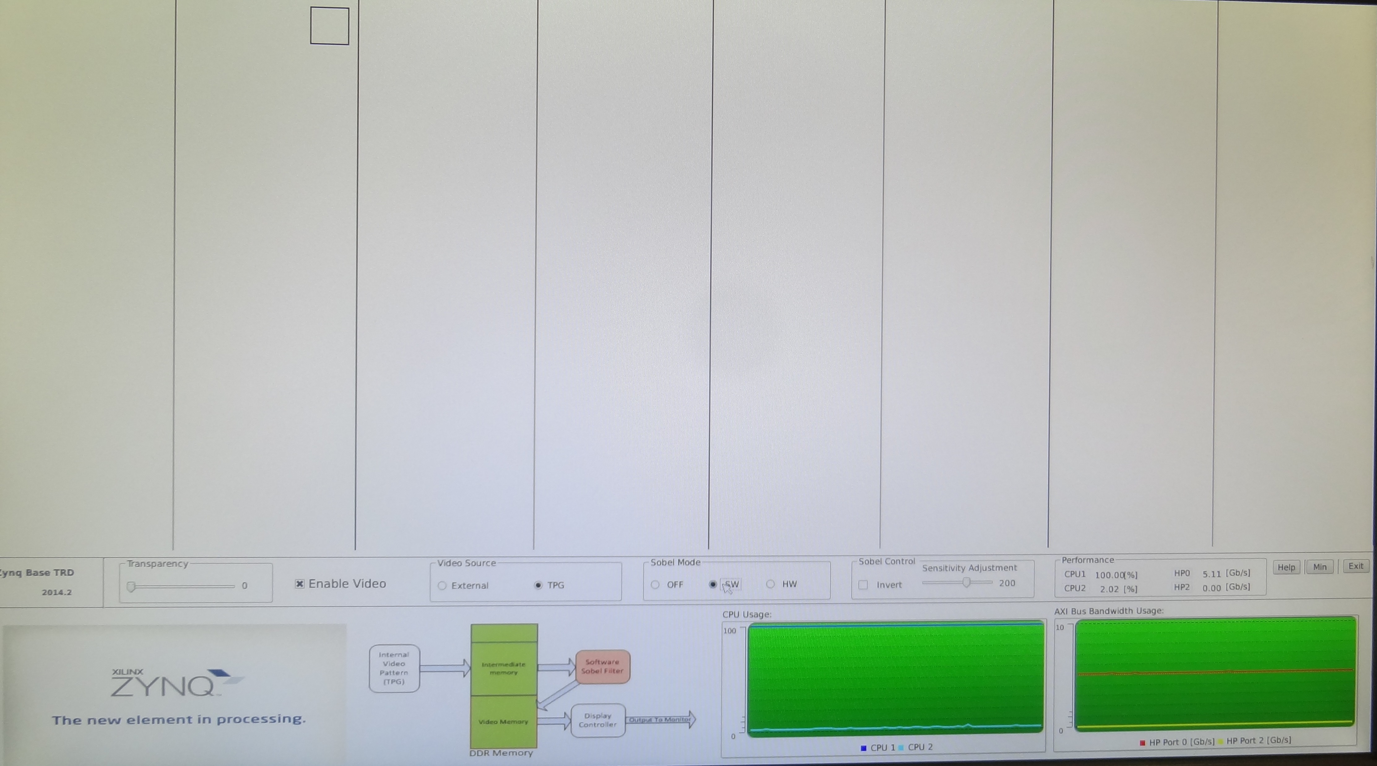
- Click the Sobel Mode to Software. Users see that the GUI starts to display the edge detecting effect of the sobel filter. Notice that the video is "jerky" and the moving box jumps around. CPUx has gone to about 100% bandwidth utilization. This is because the the sobel filter is being processed entirely in code run on CPUx. .
Exercise different options by pressing the buttons available in the GUI to evaluate the different use cases mentioned in following
Table.
| Use Case |
Video source |
|---|---|
| 1 |
Test Pattern Generator |
| 2 |
External video |
NOTE: External video is applicable only if:
a) Ready to test : ready_to_test/devicetree_fmc.dtb is renamed to devicetree.dtb and copied to SD partition.
b) In "Petalinux" section step 5.2.2 is selected.
| Filter mode |
|
|---|---|
| 6 |
None / SW / HW |
- TPG interference
- External video (available with the optional ZVIK FMC module)
Sobel Filter modes are explained as follows:
- Sobel OFF No processing done. Sobel filter is bypassed.
- Sobel – SW Video processing (edge-detection filter) done by software code running on the PS.
- Sobel – HW Video processing (edge-detection filtering) done by PL. Observe CPU utilization going down (to approximately 0) and the frame rate jumping to 60 fps.
While exercising the modes described above, one can observe AXI bus bandwidth utilization and CPU utilization on the graphs in the Qt GUI application.
Click Exit button on the GUI using the mouse to quit the application and return the user to linux console.
The application can be restarted by typing the following at the Linux command prompt:
zynq> run_video.sh -qt -r 1920x1080
2.4 Run Qt GUI Application in 720p mode
Prerequisite:
Monitor supporting 720p mode, as current design has a strict check for supported resolution.
For more information refer to Appendix 8.1 EDID section.
Command line resolution switch utility is added to dynamically change the resolution .
To use this feature application has to be started using -r option followed by input resolution.
Steps for Running QT based GUI in 720p mode.
a) Follow similar steps as mentioned in 2.3 subsection.
b) Exit QT application by clicking on Exit button.
c) Type these commands at the Linux command prompt into the host PC based terminal
zynq> run_video.sh -qt -r 1280x720
2.5 Run UART Menu Application in 1080p mode
A Linux application with command line menu is also provided with the package. This application provides options to the user to exercise different modes of the video demonstration over UART communications.
Note: The default Linux device tree binary file configures the video output resolution to 1080p @60Hz.
After setting the board as explained in Section 2.2, running the UART menu based application is explained in this section.
Steps for running the UART Menu-Based application demo
Power on the ZC702 board.
Start the installed UART terminal program on your host PC (e.g., Tera Term on a Windows PC, GtkTerm on a Linux PC).
Use the following UART configuration: Baud rate = 115200, bits = 8, parity = none, and stop bits = 1.
Note: This step is required to view debug information or to run the UART Menu-Based Demonstration application.
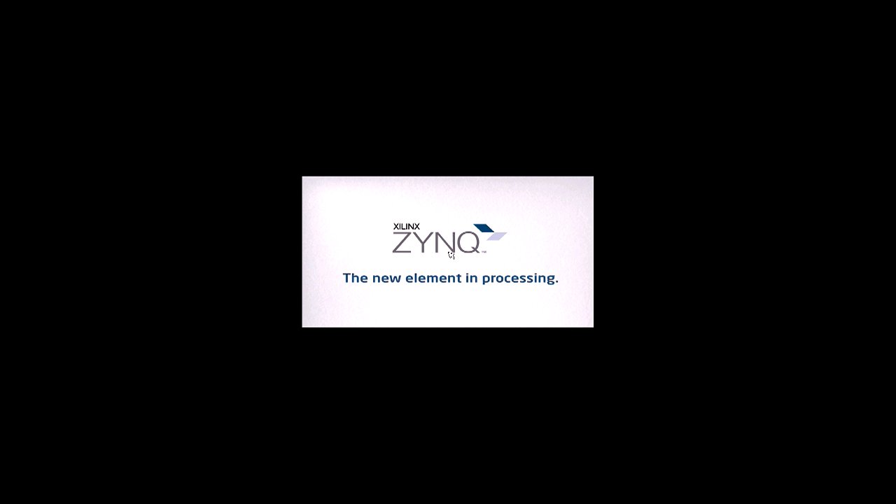
Wait for the ZC702 board to be configured and booted with Linux. After approximately 2 minutes, a XILINX ZYNQ banner displays on the monitor.
The Qt-based video demonstration application starts. The GUI application shows up at the bottom of the display monitor.
Click Exit button on the GUI using the mouse to quit the application and return the user to Linux console.
Go to the UART terminal started on the host PC.
Type these commands at the Linux command prompt into the host PC based UART terminal:
zynq> run_video.sh -cmd
The menu-based video application demonstration starts as shown in the Figure:
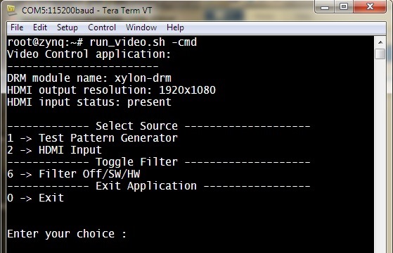
Exercise different options by entering the use case number displayed in the below Table against
Enter your choice : on the terminal.
Table.
| Use Case |
Video source |
|---|---|
| 1 |
Test Pattern Generator |
| 2 |
External video |
NOTE: External video is applicable only if:
a) Ready to test : ready_to_test/devicetree_fmc.dtb is renamed to devicetree.dtb and copied to SD partition.
b) In "Petalinux" section step 5.2.2 is selected.
| Filter mode |
|
|---|---|
| 6 |
None / SW / HW |
2.6 Run UART Menu Application in 720p mode
Prerequisite: Monitor supporting 720p mode as current design has a strict check for supported resolution.
For more information refer to Appendix 8.1 EDID section.
To use this feature application has to be started using -r option followed by input resolution.
Steps for Running UART Menu based Demonstration Application in 720p mode.
a) Follow similar steps as mentioned in 2.5 subsection.
b) Exit UART application [enter 0 to exit ].
c)Type these commands at the Linux command prompt into the host PC based terminal:
zynq> run_video.sh -cmd -r 1280x720
3 Vivado
This section explains how to generate the FPGA hardware bitstream using the Xilinx Vivado tool and how to export the hardware platform to Xilinx Software Development Kit (XSDK) for software application development.3.1 Building the Bitstream
Steps for building the FPGA hardware bitstream
Launch Vivado :
- On Windows 7, select Start > All Programs > Xilinx Design Tools > Vivado 2014.4 > Vivado 2014.4
- On Linux, enter vivado at the command prompt.
NOTE for Windows users: Copy directory 'vivado' that is at '$ZYNQ_TRD_HOME/hardware/' to a drive directly because of windows file path limit (255 characters) before following the next steps for building hardware bitstream.
From the Vivado welcome screen, in TCL console, run following commands
1. cd $ZYNQ_TRD_HOME/hardware/vivado
2. source ./scripts/project.tcl
The above step creates a project 'zynq_base_trd_2014.4'.
In the Flow Navigator pane on the left-hand side under Program and Debug, click Generate Bitstream. The bitstream will be generated at $ZYNQ_TRD_HOME/hardware/vivado/project/zynq_base_trd_2014.4.runs/impl_1/system_top_wrapper.bit
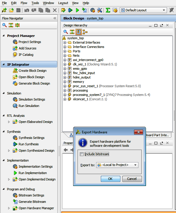
Exporting the Hardware Platform to XSDK
3.2 Steps for exporting the hardware platform to XSDK
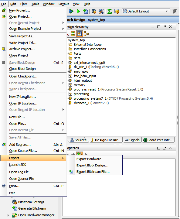
From the Vivado menu bar, select File > Export > Export Hardware
In the Export Hardware window press OK. The SDK hardware platform will be exported to $ZYNQ_TRD_HOME/hardware/vivado/project/zynq_base_trd_2014.4.sdk/
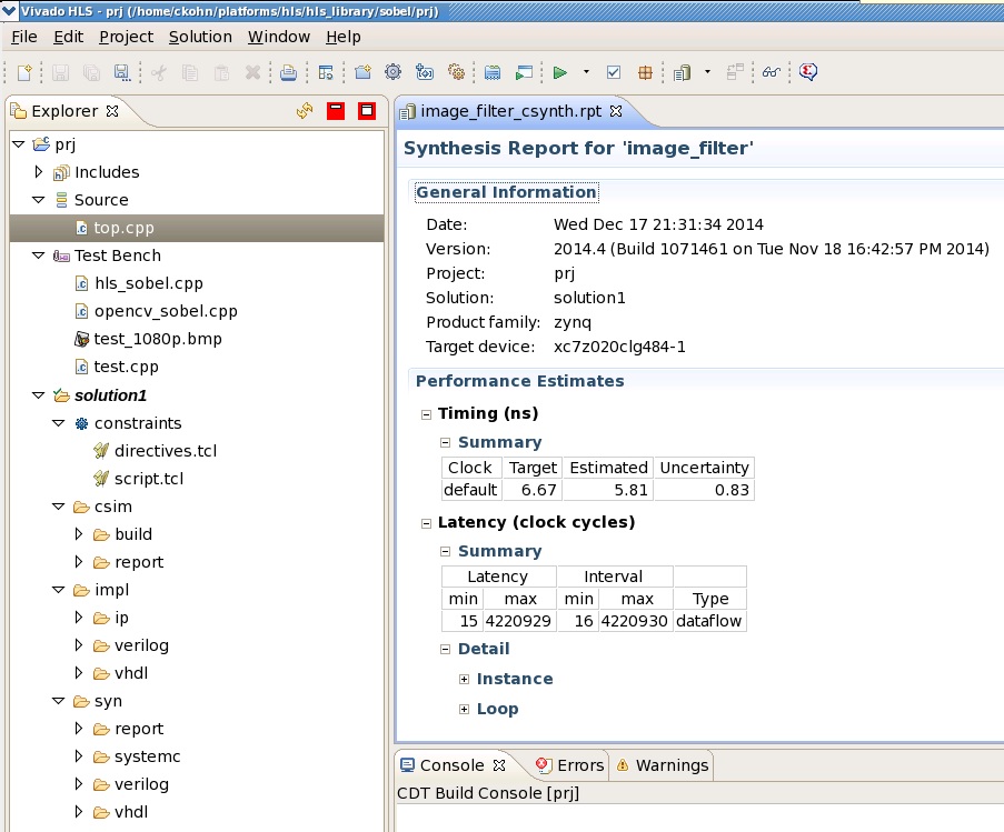
4 Vivado HLS
Vivado HLS Flow for generating Sobel filter Vivado IPVivado HLS provides a tool and methodology for migrating algorithms coded in C, C++ or System-C from the Zynq PS onto the PL by generating RTL code.
The Sobel filter IP core used in the Zynq Base TRD was generated using this approach.
Pre-generated Sobel IP core is available at $ZYNQ_TRD_HOME/hardware/vivado/srcs/ip/xilinx_com_hls_image_filter_1_0/
To generate the Sobel filter Vivado IP, navigate to $ZYNQ_TRD_HOME/hardware/vivado_hls/sobel and run:
bash> vivado_hls -f run.tcl
To use this IP and generate bitstream, replace the content of $ZYNQ_TRD_HOME/hardware/vivado/src/ip/xilinx_com_hls_image_filter_v1_0/ by content of the zip file generated by Vivado HLS tool.
And follow the steps in section 3.1 'Generating the bitstream'
To open the generated project in GUI mode, run:
bash> vivado_hls -p prj
5 Petalinux
5.1 Installation of Petalinux SDK
Prerequisites- 2GB RAM (recommended minimum for Xilinx tools)
- Pentium 4 2GHz CPU clock or equivalent.
- 5 GB free HDD space.
- Supported OS:
- RHEL 5 (32-bit or 64-bit)
- RHEL 6 (32-bit or 64-bit)
- SUSE Enterprise 11 (32-bit or 64-bit)
- PetaLinux 2014.4 release package.
- Valid PetaLinux license.
- Common system packages and libraries are installed on your workstation. The installation process will check for these. See the section Required Tools and Libraries for more details. For detailed information refer petalinux reference guide UG1144 .
Extract the PetaLinux Package
Assuming all the prerequisites described in the last subsection are satisfied, PetaLinux installation is very straight forward.Without any options, the installer will installl as a subdirectory of the current directory. Alternatively, an installation path may be specific . Run the downloaded petalinux installer.
NOTE: Ensure that petalinux installation path is kept short as petalinux build may fails if path exceeds 255 chars
bash> ./petalinux-v2014.4-final-installer.run
PetaLinux will be installed in the petalinux-v2014.4-final directory, directly underneath the working directory of this command.
So, if you install the installer into your home directory /home/user, PetaLinux will be installed in /home/user/petalinux-v2014.4-final.
Setup PetaLinux Working Environment
After extracting the package, the remainder of the setup is completed automatically.
1. Go to the PetaLinux root directory by running this command on the command console:
cd <path-to-installed-PetaLinux>
e.g.:
bash> cd /home/user/petalinux-v2014.4-final
INFO: Checking installation environment requirements...
INFO: Checking free disk space
INFO: Checking installed tools
INFO: Checking installed development libraries
INFO: Checking network and other services
WARNING: No tftp server found - please refer to "PetaLinux SDK Installation Guide" for its impact and solution
2. Source the appropriate PetaLinux setup script by running this command on the command console:
For Bash:
bash> source settings.sh
Below is an example of the output from sourcing the setup script for the first time:
PetaLinux environment set to ’/home/user/petalinux-v2014.4-final
INFO: Checking free disk space
INFO: Checking installed tools
INFO: Checking installed development libraries
INFO: Checking network and other services
WARNING: No tftp server found - please refer to "PetaLinux SDK Installation Guide" for its impact and solution
The post-install step only occurs once. Subsequent runs of the settings script should be much quicker, and simply output a confirmation message such as that shown below:
PetaLinux environment set to ’/home/user/petalinux-v2014.4-final'
Verify Petalinux Installation
Verify that the PetaLinux working environment has been set:
bash> echo $PETALINUX
Environment variable "$PETALINUX" should point to the path to the installed PetaLinux. Your echo output may be different from this example, depending upon where you installed PetaLinux.
5.2 Build Petalinux images
Finally, it’s time to build your petalinux image.User need to setup the Git on the PC check step 1.4 Prerequisite.
Linux is downloaded using git in build process of Petalinux.
Alternatively user can download a tar of linux-xlnx and extract it into
$(ZYNQ_TRD_HOME)/software/petalinux/build/linux/kernel/download/linux-xlnx, prior to "petalinux-build" command.
NOTE: In TRD we are using two device tree for video pipeline.
a) video-cap.dtsi
Configures video input pipeline for only Test pattern generator (TPG) mode.
40080000.axi_tpg (source)-->(sink) axi_video_cap
b) video-cap-fmc.dtsi and fmc-imageon.dtsi
Configures video input pipeline for external video and test pattern generator.
adv7611 12-004c(source) --> (sink) 40080000.axi_tpg (source) -->(sink) axi_video_cap
Building petalinux binaries is categorized into two sections.
a) Build petalinux images (With TPG support)
b) Build petalinux images ( With TPG and external video support)
NOTE : Depending on configuration (with/without) FMC , user needs to select either step 5.2.1 or 5.2.2.
5.2.1 Building petalinux images (No FMC)
Run ’petalinux-build’ in the petalinux SDK project directory to build the PetaLinux system image:bash> cd $ZYNQ_TRD_HOME/software/petalinux bash> petalinux-build bash> petalinux-package --image -c kernel --format uImage
The console shows the compilation progress. e.g.:
INFO: Checking component...
INFO: Generating make files and build linux
INFO: Generating make files for the subcomponents of linux
INFO: Building linux
<snip>
And the compilation log are stored in build.log in the $(ZYNQ_TRD_HOME)/software/petalinux/build directory
5.2.2 Building petalinux images (FMC)
Run ’petalinux-build’ in the petalinux SDK project directory to build the PetaLinux system image:bash> cd $ZYNQ_TRD_HOME/software/petalinux/subsystems/linux/configs/device-tree bash> vim system-top.dts
/include/ "zynq-pl.dtsi"
/include/ "fmc-imageon.dtsi" For FMC setup [UNCOMMENT THIS LINE ]
bash> vim zynq-pl.dtsi
/include/ "video-cap-fmc.dtsi" For FMC setup [UNCOMMENT THIS LINE]
bash> petalinux-build
bash> petalinux-package --image -c kernel --format uImage
INFO: Checking component...
INFO: Generating make files and build linux/device-tree
INFO: Generating make files for the subcomponents of linux/device-tree
INFO: Building linux/device-tree
<snip>
And the compilation log are stored in build.log in the $(ZYNQ_TRD_HOME)/software/petalinux/build directory.
5.3 Generate BOOT image for Zynq
Follow the steps below to generate the SD boot image (BOOT.BIN).
petalinux-package --boot --fsbl <Path to FSBL image> --fpga <Path to FPGA bitstream> --uboot<=Path to uboot image> -o <output file>
Required option for boot image package:
--fsbl <FSBL_ELF> Path to FSBL ELF image location
Options for boot image package:
--force Force overwrite the boot binary image
--fpga <BITSTREAM> Path to FPGA bitstream image location
--uboot[=<UBOOT_IMG>] Path to the u-boot elf image location
(default <PROJECT>/images/linux/u-boot.elf)
Prerequisite
petalinux-package command requires bootgen utility to be present in $PATH. Refer Vivado tools installation section for further information.
bash> cd $ZYNQ_TRD_HOME/software/petalinux/images/linux
bash> petalinux-package --boot --fsbl zynq_fsbl.elf
--fpga $ZYNQ_TRD_HOME/hardware/vivado/project/zynq_base_trd_2014_4.runs/impl_1/system_top_wrapper.bit --uboot
Bitstream : $ZYNQ_TRD_HOME/hardware/vivado/project/zynq_base_trd_2014.4.runs/impl_1/system_top_wrapper.bit
cd $ZYNQ_TRD_HOME/software/petalinux/images/linux
SD BOOT mode Petalinux Deployment Binaries:
a) BOOT.BIN
b) devicetree.dtb ( No FMC ,only TPG) {renamed version of $(ZYNQ_TRD_HOME)/software/petalinux/images/linux/system.dtb}
c) devicetree_fmc.dtb (FMC configured , TPG+external) {renamed version of $(ZYNQ_TRD_HOME)/software/petalinux/images/linux/system.dtb}
d) autostart.sh
e) uImage
f) uramdisk.image.gz {renamed version of $(ZYNQ_TRD_HOME)/software/petalinux/images/linux/urootfs.cpio.gz}
g) bin/
_|-run_video.sh
_|-video_cmd
_|-video_qt
Zynq Base TRD uses autostart.sh to invoke video QT application on start-up.
Comment below snippet to disable auto-start.
#run_video.sh -qt &
6 XSDK
This section demonstrates building of TRD applications using Xilinx software development kit (XSDK) .Launch Xilinx SDK:
- On Linux, enter xsdk at the command prompt.
In the Workspace Launcher window, click Browse and navigate to $ZYNQ_TRD_HOME/software/xsdk, then click OK.
Close the welcome screen.
6.1 Import project
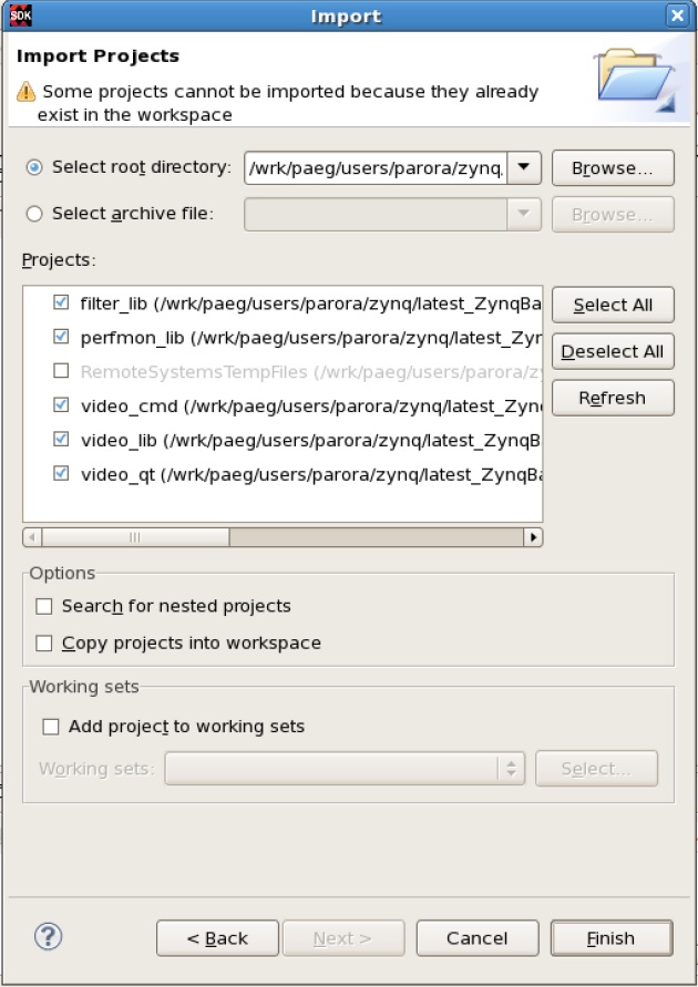
To import the performance library (perfmon_lib), filter library (filter_lib) , video library (video_lib) , video command-line application (video_cmd) and QT application (video_qt) into the SDK workspace.- Select File > Import.
- In the Import wizard, expand the General folder, select Existing Projects into Workspace, and click Next. All projects are located at the top-level inside your SDK workspace.
- Click Browse and navigate to $ZYNQ_TRD_HOME/software/xsdk. Press OK.
- Make sure the perfmon_lib, filter_lib , video_lib , video_cmd and video_qt are checked . Press Finish.
6.2 Build project
The following third-party libraries and corresponding header files are required to compile the application:Pre-compiled libraries are shipped as part of the TRD under $ZYNQ_TRD_HOME/software/pre-built/lib. If you wish to build the above libraries from source, follow the below instructions:
- For V4l2 and DRM libraries refer to Wiki instructions.
- For QT/QWT libraries refer to Wiki instructions.
- For OpenCv/FFmpeg refer to link.
In XSDK's Project Explorer, perform the following steps:
- Right click on video_cmd project ,and select Build Project. Since video command-line project adds "video_lib" and "filter_lib" as a project references , it is automatically selected and build by XSDK.
INFO: Please ensure $ZYNQ_QT_INSTALL environment variable is set , before building QT application. - Right click on video_qt project ,and select Build Project. Since video QT project adds "video_lib", "filter_lib" and "perfmon_lib" as a project references , it is automatically selected and build by XSDK.
6.3 Deploy and Debugging applications
This section explain about deploying and debugging applications over sftp interface.a. Booting Zynq ZC702 board with binary of 2014.4 Zynq Base TRD.
- BOOT.BIN
- uImage
- devicetree.dtb {renamed version of $(ZYNQ_TRD_HOME)/software/petalinux/images/linux/system.dtb}
- devicetree_fmc.dtb {renamed version of $(ZYNQ_TRD_HOME)/software/petalinux/images/linux/system.dtb}
- uramdisk.image.gz {renamed version of $(ZYNQ_TRD_HOME)/software/petalinux/images/linux/urootfs.cpio.gz}
b. Setting up new RSE (Remote System Explorer).
Pre-requisite: Identify the IP assigned to the eth0 interface, Check the connection by running ping between the PC and Zynq ZC702 Board.
Say IP of Zynq ZC702 Board is 192.168.1.10 for eth0 interface
- On SDK Open Window > open prospective > Other.., Click Remote System Explorer.
- On the leftmost panel right click and select new connections, choose SSH Only and Click on Next.
- Give Host name 192.168.1.10 [This is the IP detected on Zynq Board].
- In the project explorer panel expand the Sftp files and click on Root.
- In the Enter Password window give UserID and Password as "root".
- Switch to C/C++ project explorer window.
- select the Binary image of by right click and choose Run As option.
- Choose Run Configuration in the option, Select 192.168.1.10 and Click on property icon, write "/usr/bin" in the bar.
This step identify the location where you want to keep your binary image. - In the Remote Absolute path give "/usr/bin/video_cmd"
- Click run and see the output on the screen and options in the console.
- Select the video_cmd binary by right click and choose Debug As option.
- Select the Remote system explorer and see the output on the Debug prospective window.
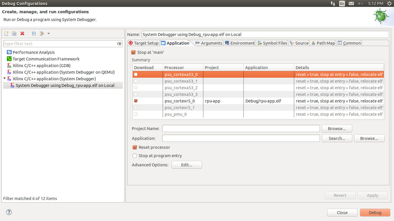
6.4 System Performance Analysis
The following steps explain how to use XSDK's performance analysis tool to monitor several PS and PL performance metrics of the design. A JTAG cable needs to be connected for XSDK to communicate with the board. Once the system is booted, run the following command to start the Qt application with the built-in monitoring function disabled. Disabling the built-in monitoring is required so XSDK can access the performance monitor exclusively.
zynq> video_qt --no-apm
In XSDK, perform the following steps:
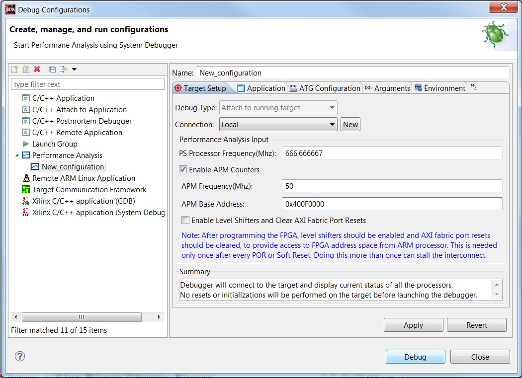
- Click Run > Debug Configurations...
- Double-click Performance Analysis
- For Name, enter ZC702 Base TRD 2014.4
- Check Enable APM Counters, set APM Frequency to 50 MHz and enter 0x400F0000 for APM Base Address
- Click Debug
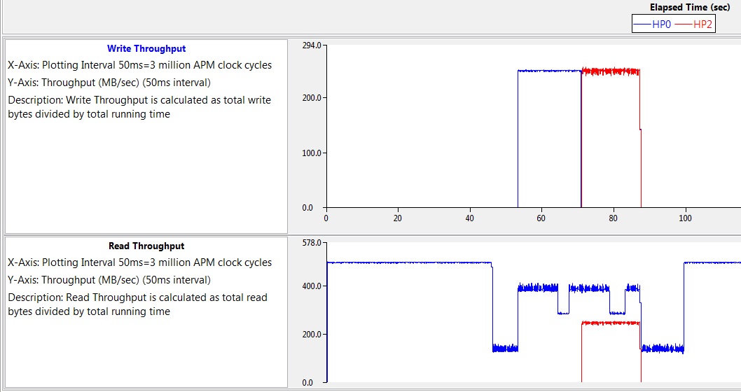
In the Performance Analysis perspective:
- Click he PL Performance tab
- On the right-hand side, click the symbol named Graph Preferences and only check Write Throughput and Read Throughput
- Next to it, click the symbol AXI Trace Preferences and only check HP0 and HP2
You can now enable and disable the video in the Qt GUI, disable and enable the hardware sobel filter, and minimize or maximize the GUI and monitor he differences in read/write throughput of the HP0 and HP2 ports in the XSDK monitor. See example below:
Similarly you can monitor various CPU metrics by switching to the PS Performance tab in XSDK.
7 References
- Documentation for Zynq-7000 SoC
- Documentation for ZC702 Evaluation Kit
- Main Xilinx wiki
- Documentation for Petalinux SDK.
8 Appendix
8.1 EDID Extended display identification data
The Extended Display Identification Data (EDID) is a data structure, with optional variants, to allow the display to inform the host about its identity and capabilities. The EDID data structure is independent of the communication protocol used between the monitor and host.EDID 2.0 Version 2 Revision 0 data structure defined a completely new EDID data structure based on 256-byte records.
To check if a display source supports a particular resolution its EDID information can be queried. There are lot of available software tools for managing EDID information.
Example: Extron EDID Manager® is a software tool that can be a useful aid in troubleshooting potential EDID compatibility issues between a display and the source connected to it.
The software allows user to read the display's EDID and generate a report, providing detailed information about the display device.
http://www.extron.com/product/software.aspx?id=edidmanager&s=5
Current Linux DRM driver has in default EDID check enabled , so on switching resolution it will check if connected monitor supports that resolution .
If monitor supports the specified resolution it switches successfully or else return an error.
root@zynq:~# run_video.sh -cmd -r 1280x720
ERROR(../src/drm_helper.c:266) : Input Resolution 1280x720 not supported by the monitor !
Aborted
© Copyright 2019 - 2022 Xilinx Inc. Privacy Policy