Solution Zynq PL Programming With FPGA Manager
- Confluence Wiki Admin (Unlicensed)
- Manne, Nava kishore
- navam (Unlicensed)
Table of Contents
Introduction
The information on this page is specific to Zynq-7000 SoC devices. The Zynq-7000 Programmable Logic (PL) can be programmed either using First Stage Boot-loader (FSBL), U-Boot or through Linux.
This page provides the details about programming the PL from Linux world.
References:
https://github.com/Xilinx/linux-xlnx/blob/master/Documentation/driver-api/fpga
HW IP Features
- Full-Bitstream and partial Bitstream loading.
- Encrypted and Authenticated Bitstream loading.
Features supported in the Driver
- Full-Bitstream Bitstream loading.
- Encypted Bistream loading with Device-Key
Missing Features, Known Issues and Limitations
- No support for partial Bitstream loading.
- No support for Authenticated and Encrypted Bitstream loading.
- It supports loading only .bin format files into the PL. These .bin files must be created using Bootgen and no other file formats are supported. Refer to this link for steps to generate a .bin file from a .bit file.
- The existing Overlay fame-work allows the removal of overlay' only if it's the top-most one. So please follow the LIFO order to remove overlays from live tree.
- for more details ref this link: https://elixir.bootlin.com/linux/v6.6.32/source/drivers/of/overlay.c#L1137
NOTE:
The descriptions in subsequent sections refer to use of Device Tree Overlay (DTO) fragments with FPGA manager framework. It has to be noted that the generation of DTO fragments are not supported in official Xilinx Petalinux release.
Below sections describe steps for manual creation of pl.dtsi (contains the DTO fragment) to be used along with Xilinx 2018.3 Linux.
Kernel Configuration
The following config options should be enabled in order to use FPGA Manager (In zynq_defconfig this options are enabled by default)Zynq FPGA Manager Configuration:
Select: Device Drivers ---> FPGA Configuration Framework
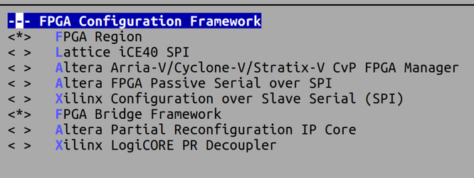
DT overlay ConfigFS interface Configuration:
This is required only if the user is using to the Bitstream using DTO
Select: Device Drivers --> Device Tree and Open Firmware support
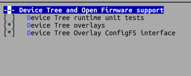
Contiguous Memory Allocator Configuration:
CONFIG_CMA
Select: Memory Management options ---> Contiguous Memory Allocator

CONFIG_DMA_CMA
Library routines--> DMA Contiguous Memory Allocator

Device-tree
devcfg: devcfg@f8007000 {
        compatible = "xlnx,zynq-devcfg-1.0";
        interrupt-parent = <&intc>;
        interrupts = <0 8 4>;
        reg = <0xf8007000 0x100>;
        clocks = <&clkc 12>, <&clkc 15>, <&clkc 16>, <&clkc 17>, <&clkc 18>;
        clock-names = "ref_clk", "fclk0", "fclk1", "fclk2", "fclk3";
        syscon = <&slcr>;
};
fpga_full: fpga-full {
       compatible = "fpga-region";
       fpga-mgr = <&devcfg>;
       #address-cells = <2>;
       #size-cells = <2>;
};
Reference Link for device-tree bindings:
https://github.com/Xilinx/linux-xlnx/blob/master/Documentation/devicetree/bindings/fpga/xilinx-zynq-fpga-mgr.yaml
FPGA programming using Device Tree Overlay (DTO)
The Device Tree Overlay (DTO) is used to reprogram an FPGA while Linux is running. The DTO overlay will add the child node and the fragments from the .dtbo file to the base device tree,, The newly added device node/drivers will be probed after bitstream programming
DTO contains:
- Target FPGA Region
- "target-path" or "target" - The insertion point where the the contents of the overlay will go into the live tree.
target-path is a full path, while target is a phandle. - FPGA Image firmware file name
- "firmware-name" - Specifies the name of the FPGA image file on the firmware search path.
The search path is described in the firmware class documentation. - Image specific information
- external-fpga-config : boolean, set if the FPGA has already been configured prior to Linux boot up. - Child devices
- child nodes corresponding to hardware that will be loaded in this region of the FPGA.
Steps for programming the bitstream using overlay: Refer
Example:
//Device Tree Example: Full Reconfiguration without Bridges
// HSI Generated overlay/pl.dtsi file.
// Enable the axi-gpio interface
/dts-v1/;
/plugin/;

/ {

    fragment@0 {

        target = <&fpga_full>;
        #address-cells = <1>;
        #size-cells = <1>;

        __overlay__ {
            #address-cells = <1>;
            #size-cells = <1>;

            firmware-name = "design_1_wrapper.bit.bin";
        };
    };

    fragment@1 {

                target = <&amba>;
                __overlay__ {
                        axi_gpio_0: gpio@a0000000 {
                                #gpio-cells = <2>;
                                compatible = "xlnx,xps-gpio-1.00.a";
                                gpio-controller ;
                                reg = <0x0 0xa0000000 0x0 0x10000>;
                                xlnx,all-inputs = <0x0>;
                                xlnx,all-inputs-2 = <0x0>;
                                xlnx,all-outputs = <0x1>;
                                xlnx,all-outputs-2 = <0x0>;
                                xlnx,dout-default = <0x00000000>;
                                xlnx,dout-default-2 = <0x00000000>;
                                xlnx,gpio-width = <0x8>;
                                xlnx,gpio2-width = <0x20>;
                                xlnx,interrupt-present = <0x0>;
                                xlnx,is-dual = <0x0>;
                                xlnx,tri-default = <0xFFFFFFFF>;
                                xlnx,tri-default-2 = <0xFFFFFFFF>;
                        };
                };
        };

};
Tools Required
- device-tree-xlnx
- bootgen
- DTC
NOTE:
- To support device-tree overlay the DTC compiler version should be >= 1.4.4
Images Required for testing
- FSBL
- u-boot
- Linux Image (uImage)
Refer below link to build the above images:
http://www.wiki.xilinx.com/Zynq+Linux - Device-tree (system.dtb)
Device-tree Compilation with DT-Overlay
A utility called device tree compiler (DTC) is used to compile the DTS file into a DTB file. DTC is part of the Linux source directory. linux-xlnx/scripts/dtc/ contains the source code for DTC and needs to be compiled in order to be used.- $ ./scripts/dtc -O dtb -o my_dts/system-top.dtb -b 0 -@ my_dts/system-top.dts
Note: To support the device-tree overlay the base tree should be compile with -@ flags to generate the symbols.
- $ ./scripts/dtc -O dtb -o my_dts/system-top.dtb -b 0 -@ my_dts/system-top.dts
- Bin file
- DTBO file
Generating .bin from .bit file using Bootgen
bootgen -image Full_Bitstream.bif -arch zynq -process_bitstream bin
all:
{
        design_1_wrapper.bit /* Bitstream file name */
}
Required Steps to Create the DT-Overlay Fragment for the Given HDF
- Clone the device-tree-xlnx repo:
git clone https://github.com/Xilinx/device-tree-xlnx.git - Helper script: dt_overaly.tcl
Command: xsct dt_overaly.tcl system.hdf ps7_cortexa9_0 device-tree-xlnx output_dir (or) xsct dt_overaly.tcl system.xsa ps7_cortexa9_0 device-tree-xlnx output_dir
Example: xsct dt_overaly.tcl system.hdf ps7_cortexa9_0 ${DTS_REPO}/device-tree-xlnx overlay
The command will create the overlay file with the required DT-Overlay fragments (overlay/pl.dtsi)
// HSI Generated overlay/pl.dtsi file.
// Enable the axi-gpio interface
/dts-v1/;
/plugin/;

/ {

    fragment@0 {

        target = <&fpga_full>;
        #address-cells = <1>;
        #size-cells = <1>;

        __overlay__ {
            #address-cells = <1>;
            #size-cells = <1>;

            firmware-name = "design_1_wrapper.bit.bin";
        };
    };

    fragment@1 {

                target = <&amba>;
                __overlay__ {
                        axi_gpio_0: gpio@a0000000 {
                                #gpio-cells = <2>;
                                compatible = "xlnx,xps-gpio-1.00.a";
                                gpio-controller ;
                                reg = <0x0 0xa0000000 0x0 0x10000>;
                                xlnx,all-inputs = <0x0>;
                                xlnx,all-inputs-2 = <0x0>;
                                xlnx,all-outputs = <0x1>;
                                xlnx,all-outputs-2 = <0x0>;
                                xlnx,dout-default = <0x00000000>;
                                xlnx,dout-default-2 = <0x00000000>;
                                xlnx,gpio-width = <0x8>;
                                xlnx,gpio2-width = <0x20>;
                                xlnx,interrupt-present = <0x0>;
                                xlnx,is-dual = <0x0>;
                                xlnx,tri-default = <0xFFFFFFFF>;
                                xlnx,tri-default-2 = <0xFFFFFFFF>;
                        };
                };
        };

};
dtc -O dtb -o pl.dtbo -b 0 -@ pl.dtsi
For more info about DTG please refer the below link
http://www.wiki.xilinx.com/Build%20Device%20Tree%20Blob
Test Procedure
Using Device Tree Overlay
Steps to Load Full BitstreamOnce the Linux is up run the below commands to load the required Full Bitstream.
1) Set flags for Full Bitstream.
- echo 0 > /sys/class/fpga_manager/fpga0/flags
2) Copy the Full Bitstream (.bin) and pl.dtbo files into firmware folder
- mount /dev/mmcblk0p1 /media/
- mkdir -p /lib/firmware
- cp /media/design_1_wrapper.bit.bin /lib/firmware/design_1_wrapper.bit.bin
- cp /media/pl.dtbo /lib/firmware/
3) Apply DTBO (To add device nodes)
- mkdir /configfs
- mount -t configfs configfs /configfs
- cd /configfs/device-tree/overlays/
- mkdir full
- echo -n "pl.dtbo" > full/path
4) Steps to remove device nodes
- rmdir full
Steps to Re-Load Full Bitstream
1) Remove The overlay file will be applied earlier.
- rmdir full
2) Set flags for Full Bitstream.
- echo 0 > /sys/class/fpga_manager/fpga0/flags
3) Copy the Full Bitstream and pl.dtbo files into firmware folder
- cp /media/design_1_wrapper.bit.bin /lib/firmware/design_1_wrapper.bit.bin
- cp /media/new-pl.dtbo /lib/firmware/
3) Apply DTBO
- mkdir full
- echo -n "new-pl.dtbo" > full/path
Expected Output Using DTBO
root@xilinx-zc702-2018_1:/configfs/device-tree/overlays# echo -n "pl.dtbo" > full/path
fpga_manager fpga0: writing zc702_wrapper.bit.bin to Xilinx Zynq FPGA Manager
XGpio: /amba/gpio@41200000: registered, base is 902
root@xilinx-zc702-2018_1:/configfs/device-tree/overlays#
Using sysfs interface
Once the linux is up run the below commands to load the Bitstream.1)Set flags for Full Bitstream.
- echo 0 > /sys/class/fpga_manager/fpga0/flags
2) Loading Bitstream into PL.
- mkdir -p /lib/firmware
- cp /media/design_1_wrapper.bit.bin /lib/firmware/
- echo design_1_wrapper.bit.bin > /sys/class/fpga_manager/fpga0/firmware
Steps for programming the Encrypted Bitstream
1)Set flags for Encrypted Bitstream
- echo 0x4 > /sys/class/fpga_manager/fpga0/flags
2)Load the Bitstream
- mkdir -p /lib/firmware
- cp /media/enrypted.bit.bin /lib/firmware/
- echo enrypted.bit.bin > /sys/class/fpga_manager/fpga0/firmware
Expected Output Using Sysfs
root@Xilinx:~# mount /dev/mmcblk0p1 /media/
root@Xilinx:~#mkdir -p /lib/firmware
root@Xilinx:~# echo 0 > /sys/class/fpga_manager/fpga0/flags
root@Xilinx:~# cp /media/system_wrapper.bit.bin /lib/firmware/
root@Xilinx:~# echo system_wrapper.bit.bin > /sys/class/fpga_manager/fpga0/firmware
[  120.266851] fpga_manager fpga0: writing system_wrapper.bit.bin to Xilinx Zynq FPGA Manager
root@Xilinx:~# devmem 0xA0000000
0x00000000
Change Log
2025.1
- fpga: zynq-fpga: Rename 'timeout' variable as 'time_left'
- fpga: zynq-fpga: Convert to platform remove callback returning void
- FPGA Manager framework upgraded to 6.12v
2024.2
- None.
2024.1
- fpga: zynq-fpga: Convert to devm_platform_ioremap_resource()
- FPGA Manager framework upgraded to 6.6v
2023.2
- Revert "fpga: zynq: Add parse_header ops support"
2023.1
- fpga: zynq: Add parse_header ops support
2022.2
- fpga: zynq-fpga: Ensure proper xCAP interface switch
2022.1
FPGA Manager framework upgraded to 5.15v
2021.2
- None
2021.1
- None
2020.2
Summary:
- fpga: zynq: Fix incorrect variable type
Commits:
- d390930 fpga: zynq: Fix incorrect variable type
2020.1
- None
2019.2
- None
2019.1
- None
2018.3
- None
2018.2
- None
2018.1
- None
Related Links
https://github.com/Xilinx/linux-xlnx/blob/master/drivers/fpga/zynq-fpga.c© Copyright 2019 - 2022 Xilinx Inc. Privacy Policy