Zynq UltraScale+ MPSoC Power Off Suspend
Zynq UltraScale+ MPSoC Power Off Suspend
Table of Contents
Introduction
Power Off Suspend is a power state that consumes less power than Deep Sleep, but offers much faster start-up time than from a complete shutdown. The cost for using the Power Off Suspend mode is 1 Mbytes of dedicated DRAM space for backing up the ZU+ operational state information, and 4 Kbytes of dedicated Flash memory space for saving DDR context.
This is not a true hibernate mode, because the DRAM is in self-refresh mode and its contents are not saved to flash.
The APU can be running Linux, other OS, bare-metal application, or not running at all. The RPU can be running non-Linux OS, bare-metal application, or not running at all. All on-chip memory contents are preserved across Power Off Suspend.
Power Off Suspend is a board-level feature, which depends on an external system controller to manage the DDR while the ZU+ is powered off, and to signal the ZU+ on power-up resume. Details of the operations and interface to the external system controller is described in later sections.
By default, this feature is disabled. See ZU+ Example - Power Off Suspend for details on how to enable and use this feature.
The high level operations of this feature involve:
In this scenario, all the power domains are enabled. There is only one PM master running, but this PM master could be the APU, the RPU (lock-step or one of the split R5). All the other PM masters are either suspended or shut down.
In this scenario, the FPD and PL has been powered down, and only the RPU (lock-step or one split R5) is running.
Since the DDR controller is in FPD and has been shut down, we will need to bring up the FPD and take the DRAM out of self-refresh in order to save the state information.
Note that this will result in a short burst of power consumed by the ZU+ while the FPD and DDRC/DRAM are powered up to save the state information.
Before resume procedure starts, System controller will receive external wakeup. In order to handle wakeup System controller will power up system and set PS GPIO pin (MIO26) that is used for POS detection.
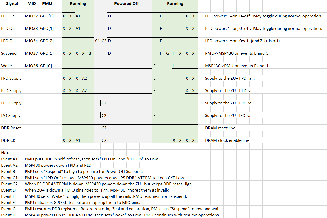
By default, two things happen on the ZCU102 board when the ZU+ shuts down:
During Power Off Suspend the MSP430 will prevent the above by:
Five PMU-to-MSP430 GPIO pins are used for the Power Off Suspend:
Warm restart indicates that the ZU+ is to resume from Power Off Suspend. Right before powering down LPD, the PMU sets MMIO37 to indicate to the MSP320 that this it is shutting down for Power Off Suspend.
Here is the list of configuration changes in all software layers required for Power Off Suspend support:
PMU firmware size increase after adding support for Power Off Suspend is ~10KB.
Power Off Suspend has been implemented for the ZCU102 board only (testing was done on a single board at room temperature, so PVT testing was not performed). The feature rely on specific on-board support, including:
On a different board, the specific board features may be different. The system controller may be a different processor, and the power rails being managed by the system controller may be different. The non-volatile storage may not be QSPI flash. The code that handles the board-specific details are encapsulated by user hooks. The user may customize these hooks when porting the Power Off Suspend feature to their boards.
On ZCU102 board, there is 1 Gbytes of non-volatile QSPI Flash memory used for saving DDR context. The MSP430 is system controller handles external power requests and Power Off Suspend requests. All board specific code is placed into pm_hooks.c/h files and it is used for implementation of listed board specific steps above. When porting the Power Off Suspend support to another board, all functions and data structures must be updated to match the resources on new board. Here is the list of data structures and functions defined in pm_hooks.c/h:
By default, the PMU saves and restores the DDR register context data to the QSPI flash at offset 0x0000 0000. To move this to a different location, the user may redefine the WRITE_ADDR and READ_ADDR macros when compiling the pm_qspi.c file.
| Deep Sleep | Power Off Suspend | Shutdown | |
| Suspend Power | 35 mW + DRAM Refresh | RTC + DRAM refresh | RTC |
| Start-up / Resume time | 25 ms (to APU starts running, before Linux) 113 ms (best case for Linux, no devices) | ~ Deep Sleep + 50 ms | 12 secs |
The APU can be running Linux, other OS, bare-metal application, or not running at all. The RPU can be running non-Linux OS, bare-metal application, or not running at all. All on-chip memory contents are preserved across Power Off Suspend.
Power Off Suspend is a board-level feature, which depends on an external system controller to manage the DDR while the ZU+ is powered off, and to signal the ZU+ on power-up resume. Details of the operations and interface to the external system controller is described in later sections.
By default, this feature is disabled. See ZU+ Example - Power Off Suspend for details on how to enable and use this feature.
Basic Operations
- Power Off Suspend will be invoked only upon the last PM master goes into suspend mode.
- All on-chip peripherals are not active when going into suspend:
- If the APU is running Linux, then Linux will save and restore peripheral running states.
- Any bare-metal APU and RPU applications are responsible for saving and restoring context and peripheral states. (That is, not provided by Xilinx.)
- One or more PM master may enable the POWER_ON wake-up source, but only the last running CPU (APU or RPU) can initiate Power Off Suspend. On power-up, the PM masters who enabled the POWER_ON wake-up source will be woken up
- In order to enable Power off suspend every active master must disable all on-chip wake sources and at least one master must enable the POWER_ON wake-up source.
- FSBL may run from APU or RPU. The APU and RPU will be powered up on resume regardless in order to execute the FSBL.
- User must power down PL before invoking Power Off Suspend. User application is responsible for resuming the IPs running in the PL.
Design
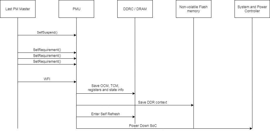
The high level operations of this feature involve:
- Suspend and Power Off:
- Detect normal suspend (LPD on) vs. power off suspend (ZU+ off).
- Saving volatile memory contents and state information.
- Signal external power controller to power down the ZU+
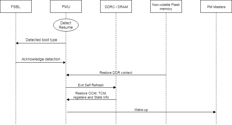
- Power On and Resume:
- Power up APU/RPU just like during POR
- Detect resume mode vs. POR.
- Restore volatile memory contents and state information.
NODE_EXTERN
When user performs the power-off suspend, the wake-up is triggered from the external entity instead of any SoC peripheral. This wake-up device is referred as NODE_EXTERN in the PMUFW.
When user sets the power-off suspend mode from the Linux user space, Linux will trigger SMC call to ATF to notify that Linux want to enter power-off suspend. So ATF will call set_wakeup_source only for NODE_EXTERN regardless of state of other wakeup sources. The PMUFW will check if NODE_EXTERN is only set for wakeup source then only it will proceed for power-off suspend during suspend procedure.
Suspend and Power Off
Full Power to Power Off Suspend
In this scenario, all the power domains are enabled. There is only one PM master running, but this PM master could be the APU, the RPU (lock-step or one of the split R5). All the other PM masters are either suspended or shut down.
LPD-only to Power Off Suspend
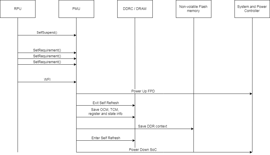
In this scenario, the FPD and PL has been powered down, and only the RPU (lock-step or one split R5) is running.
Since the DDR controller is in FPD and has been shut down, we will need to bring up the FPD and take the DRAM out of self-refresh in order to save the state information.
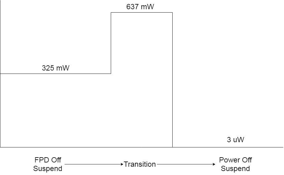
Note that this will result in a short burst of power consumed by the ZU+ while the FPD and DDRC/DRAM are powered up to save the state information.
Power On and Resume
Before resume procedure starts, System controller will receive external wakeup. In order to handle wakeup System controller will power up system and set PS GPIO pin (MIO26) that is used for POS detection.
MSP430 Power Down Procedure
By default, two things happen on the ZCU102 board when the ZU+ shuts down:
- When the ZU+ powers down, the MSP430 also powers down the DRAM.
- When the ZU+ resets, the DRAM is also gets reset.
During Power Off Suspend the MSP430 will prevent the above by:
- Keeping DRAM powered up when ZU+ powers down.
- Force the DRAM reset signal to high so the DRAM will not reset.
ZU+ / MSP430 Handshake
Five PMU-to-MSP430 GPIO pins are used for the Power Off Suspend:
- MIO32: FPD rail on/off
- MIO33: PL rail on/off
- MIO34: LPD rail on/off
- MIO37: Warm/Cold Restart sampled on LPD off request and after power-up, else used for ROU-MSP430 UART
- MIO26: Wake - external wake input.
Warm restart indicates that the ZU+ is to resume from Power Off Suspend. Right before powering down LPD, the PMU sets MMIO37 to indicate to the MSP320 that this it is shutting down for Power Off Suspend.
Configuration Changes
Here is the list of configuration changes in all software layers required for Power Off Suspend support:
- PMU uses some DDR space in order to save system state information before entering Power Off Suspend. Currently PMU saves system state information at DDR address 0x07000000. In order to support Power Off Suspend this memory region can't be used by any other master in system. For that purpose there is change in Linux device tree which mark 1MB of memory starting at 0x0700000 as reserved in order to prevent Linux of using it. Baremetal users must ensure that their app is not using this memory region. Detailed usage of memory is listed here:
- 256KB for OCM.
- 256KB for TCM.
- At most 128KB for PMU RAM, however only data and bss sections are saved
- Added srdata section in PFW linker script, used to store all PFW data required for resuming DDR operation.
- QSPI device must be enabled in hardware design file.
- ENABLE_POS build flag is required for PFW.
- ENABLE_POS build flag is required for FSBL.
- GPO section in configuration object must set default state of MIO34 pin to 1 in order to support requesting LPD power down.
PMU Code Size Impacts
PMU firmware size increase after adding support for Power Off Suspend is ~10KB.
Porting to a Different Board
Power Off Suspend has been implemented for the ZCU102 board only (testing was done on a single board at room temperature, so PVT testing was not performed). The feature rely on specific on-board support, including:
- An external system controller to
- Manage the ZU+ power rails when the ZU+ enters and exits the Power Off Suspend state.
- Manage the DDR while the ZU+ is powered off.
- Signal to the ZU+ at POR to perform Power Off Suspend resume vs. cold start.
- Non-volatile storage for saving the DDR register context information.
User Hooks
On a different board, the specific board features may be different. The system controller may be a different processor, and the power rails being managed by the system controller may be different. The non-volatile storage may not be QSPI flash. The code that handles the board-specific details are encapsulated by user hooks. The user may customize these hooks when porting the Power Off Suspend feature to their boards.
On ZCU102 board, there is 1 Gbytes of non-volatile QSPI Flash memory used for saving DDR context. The MSP430 is system controller handles external power requests and Power Off Suspend requests. All board specific code is placed into pm_hooks.c/h files and it is used for implementation of listed board specific steps above. When porting the Power Off Suspend support to another board, all functions and data structures must be updated to match the resources on new board. Here is the list of data structures and functions defined in pm_hooks.c/h:
- pmPosDdrReqs_g[] - array of PmPosRequirement data structures. Defines slaves and their capabilities required for saving DDR context. For ZCU102 board there is Qspi slave device in this list.
- PmHookPosSaveDdrContext() - Used for saving DDR context (srdata section) in available non-volatile memory device. The ZCU102 board Power Off Suspend implementation saves the DDR context in the QSPI Flash memory, which is implemented in this function. Support for accessing the QSPI flash is implemented in the pm_qspi.c/h files.
- PmQspiHWInit() - Initialize ZU+ QSPI hardware resources for accessing memory device (MIO pins, clock, reset).
- PmQspiInit() - Initialize PFW QSPI driver used for accessing memory device.
- PmQspiWrite() - Write required data to QSPI Flash memory
- PmHookFinalizePowerOffSuspend() - Called from LPD power down handler as last step before powering down LPD, used for handshake between PMU and the MSP430. On ZCU102 drive MIO37 pin high to request entering Power Off Suspend.
- PmHookPowerDownLpd() - Called from LPD power down handler in order to request power down of LPD from external power controller. On ZCU102 drive MIO34 low in order to request LPD power down from MSP430.
- PmHookInitPowerOffSuspend() - Used as part of PM module initialization in order to execute board specific steps required for enabling Power Off Suspend. On ZCU102 drive MIO34 high at startup in order to be able to send LPD power down request.
- PmHookGetBootType() - Used for detecting boot type (Power Off Suspend resume vs. Cold Start) and signaling that information to FSBL. On ZCU102 read state of MIO26 in order to detect boot type.
- PmHookRestoreDdrContext() - Used for restoring DDR context (srdata section) from available non-volatile memory device. In case of ZCU102 board restore data from QSPI Flash memory using PFW support for QSPI:
- PmQspiHWInit() - Initialize ZU+ QSPI hardware resources for accessing memory device (MIO pins, clock, reset).
- PmQspiInit() - Initialize PFW QSPI driver used for accessing memory device.
- PmQspiRead() - Read data from QSPI Flash memory
- PmHookPowerOffSuspendDdrReady() - Used during Power Off Suspend resume sequence as part of DDR driver for signaling that PMU is ready to take DDR out of self refresh.
QSPI Flash Offset
By default, the PMU saves and restores the DDR register context data to the QSPI flash at offset 0x0000 0000. To move this to a different location, the user may redefine the WRITE_ADDR and READ_ADDR macros when compiling the pm_qspi.c file.
Known Constraints
- PMU must start before FSBL. Since this is resuming from (power off) suspend, it is not booting up, and FSBL is not supposed to do anything. Some security use cases may not work in this mode (e.g. if boot encryption is required, PMU FW and FSBL must be encrypted as one image.)
- Must define FSBL_A53_TCM_ECC_EXCLUDE_VAL to 0 for FSBL code, otherwise there will be ECC errors after resume. This is because the TCM will be loaded by the PMU (not FSBL).
References
, multiple selections available,
Related content
Zynq UltraScale+ MPSoC Power Management - Linux Kernel
Zynq UltraScale+ MPSoC Power Management - Linux Kernel
More like this
Zynq UltraScale+ MPSoC Power Management - Firmware Examples
Zynq UltraScale+ MPSoC Power Management - Firmware Examples
More like this
Zynq UltraScale+ MPSoC Restart solution
Zynq UltraScale+ MPSoC Restart solution
Read with this
Zynq UltraScale+ MPSoC Power Management - ZCU102 SW Design Examples
Zynq UltraScale+ MPSoC Power Management - ZCU102 SW Design Examples
More like this
ZU+ Example - Power Off Suspend
ZU+ Example - Power Off Suspend
More like this
Zynq UltraScale+ MPSoC
Zynq UltraScale+ MPSoC
Read with this
© Copyright 2019 - 2022 Xilinx Inc. Privacy Policy
