Zynq UltraScale+ MPSoC Restart solution
- Confluence Wiki Admin (Unlicensed)
- Jain, Ronak
- Chris Althouse (Unlicensed)
Introduction
Zynq Ultrascale+ SoC is a highly complex silicon, capable of running multiple subsystems on the chip simultaneously. As such, the ZCU+ supports various type of reset from the simplest system reset to the much more complicated subsystem restart. In any system or subsystem which has a processor component and a programmable logic component, reset must entail both reset to the hardware as well as software. Reset to the hardware includes resetting of the processor, all peripherals associated with the system/subsystem, cleaning up of the memory as needed, and making sure that the interconnect is in a clean state, capable of routing traffic. Reset to the software results in the processor starting from the reset vector. However, designer must make sure that valid and clean code for system/subsystem is located at the reset vector in order to bring the system back to a clean running state.
Resets for ZCU+ are broadly divided into two categories, full system resets and subsystem restarts.
Full system resets include Power On Reset (POR), system-reset and PS-only-reset. Subsystem restarts include APU subsystems and RPU subsystem restarts.
Fully system resets are quite straight forward, at the release of the reset, all hardware are brought back to the reset state and software starts executing ROM code, with minor behavior difference between the different reset types. There are subtleties to PS-only reset which will be discussed in later sections.
Subsystem restart is more complicated. A subsystem in ZCU+ is composed of all of the components of a particular operating system. The figure below shows both Vivado's view of the Processor System (PS) as well as example subsystems as defined by the OS. Vivado' default IP configuration menu provides a flattened view, consisting of all available PS components. In the example, these components are partitioned into three separate subsystems, each running an independent operating system. Each subsystem consists of processor, list of peripherals and memory. The example shows one RPU based subsystem runs uC/OS-II, another RPU based subsystem runs FreeRTOS and an APU based subsystem runs Linux. Subsystems can be configured in Vivado's Advanced Mode.
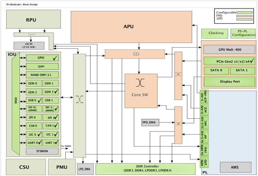 |
| Vivado IP configuration menu |
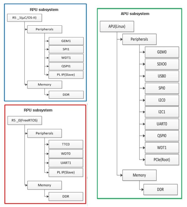 |
| Subsystem components for different operating systems |
In subsystem restart, the entire subsystem is restarted from a clean state without effecting the running of the other active subsystems defined in MPSoC. For example, in APU subsystem restart, an APU subsystem running Linux is restarted as far back as FSBL while FreeRTOS and uC/OS-II continues to function undisturbed. Similarly for RPU subsystem restart. In that case, APU subsystem continues to function undisturbed.
Subsystem restarts are managed by the platform management unit (PMU). To restart each subsystem, PMU must first ensure that all on-going axi-transactions are terminated and that no new transactions are issued. In the subsystems shown above, the interconnects which connects the components of the subsystem are not explicitly shown. However, each subsystem includes multiple interconnects and the same interconnects are used by all three subsystems. If pmu firmware resets all components in a subsystem while leaving unfinished transactions in the interconnect, the axi master and slave might both be in the reset state, but the unfinished axi transactions will remain in the interconnect, thus blocking all subsequent traffic. Because these interconnects are shared, stuck transactions in the interconnect will hang the system. It is therefore imperative that PMU ensures all transactions are completely finished before resetting each and every components in the subsystem, including the processor.
Before releasing the processor from reset, PMU must also ensure that the code in the reset vector will result in a clean system restart. In the case of RPU subsystem running standalone applications, this means either loading a clean copy of the application elf or making sure that the application code is re-entrant. In the case of APU subsystem running Linux, this means starting from an re-entrant copy of FSBL.
Getting Started
To get started adding subsystem restart feature, refer to the wiki page Zynq Ultrascale Plus Restart Solution Getting Started for 2017.4.
Supported Use Cases:
APU Subsystem Restart
Description
For a APU subsystem only restart, the designer must define the APU subsystem using Vivado's PCW. The function to restart APU subsystem is executed by the platform management unit (PMU). PMU will first properly idle all components in the APU subsystem, when all it quiet, PMU will reset each component, including the APU processors. When reset to APU is released, it will re-execute the FSBL code in OCM. The task carried out by FSBL for restart differs only slightly than that of POR. Note that FSBL is re-entrant, hence APU can simply re-execute the FSBL without having to reload a clean copy.
A flow diagram of the APU subsystem restart process is shown as follows:
 |
| APU Subsystem Restart Flow |
The start of this flow diagram represents a clean running state, Linux is up and running, as is RPU, PMU and CSU subsystems. The health of the APU subsystem is monitored by a APU watchdog timer. Linux runs a background application which periodically kicks the watchdog to prevent it from timing out. In the case of an APU subsystem hang, WDT is not kicked and times out. The timeout interrupts the PMU and results in an APU subsystem restart. Alternatively, user can invoke a apu subsystem restart by directly calling for it in Linux.
Implementation
To support any subsystem restart, an subsystem must first be defined in Vivado via isolation configuration menu.
For an APU subsystem running Linux, in addition to the default pmu subsystem, two APU subsystem are required, a secure APU system for running FSBL and ATF and another non-secure APU subsystem for running Linux. Details instructions on subsystem configuration as well as an example of a APU only subsystem can be found in the Isolation Configuration Consideration wiki page.
While APU subsystem can consists solely of PS components, it is often the case that APU subsystem also includes IP peripherals implemented in PL. Unfortunately, isolation configuration menu does not include features to assign PL IPs to different subsystems. As a result, all IPs instantiated in Vivado are added to the generated device tree source (dts) file. In order to properly define the APU subsystem, all PL IPs that do not belong in the APU subsystem need to be manually removed from the dts file.
In the process of subsystem restart, all components in the subsystem must be in the idle state, followed by reset. This is implemented for supported components in the PS. For all IPs in PL of a subsystem that are AXI slaves, no additional tasks are required to idle them but user needs to supply code to reset the slaves if desired. For PL IPs that are AXI masters, user must provide the necessary code to stop and complete all AXI transactions from the master as well as to reset it. For details on adding the idle and reset code, please see the section Idle and Reset of Peripherals
Design issue and guidelines pertaining to using resetn signal from PS to PL (ps_resetn) is detailed in the section GPIO Reset to PL
User can optionally enable the recovery and escalation features as desired.
See Building Software Section for detailed instruction on building the software.
RPU Subsystem Restart
Description
The current supported use case for RPU subsystem restart requires both the APU subsystem and one or more RPU subsystems running in lock-step or split mode. The APU subsystem running Linux is the master of the RPU subsystems and manages the life cycle of the subsystem using the remoteproc feature of OpenAmp. APU uses remoteproc to load the RPU application, start, stop the RPU, and will resync the APU subsystem with RPU subsystem after subsystem restart. APU subsystem can trigger a RPU restart sequence by first stopping the currently running RPU subsystem, loading new firmware, then starting the RPU subsystem. The trigger event for RPU subsystem restart is up to the user to implement. Some common examples of trigger events are user command, RPU watchdog timeout or message from the RPU to APU via message pipe. APU issue remoteproc command to PMU to start or stop the RPU. It is the PMU that ultimately controls the state of the RPU subsystem. A flow diagram of the RPU subsystem restart process is shown as follows:
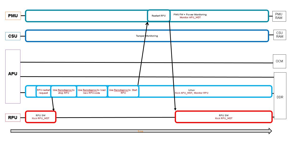
The start of this flow diagram represents a clean running state for all subsystems, Linux, RPU, PMU and CSU. In the flowchart, APU receives a RPU subsystem restart request. When APU receives the restart request, it uses remoteproc features to stop the RPU subsystem, load new firmware code, then starts the RPU subsystem again. The flow chart shows the use of a RPU watchdog timer. The RPU periodically kicks the dog. If the RPU hangs, WDT times out. in which case Linux will receive the timeout and restart the RPU subsystem.
Implementation
For a RPU subsystem only restart, the designer must define the RPU subsystem using Vivado's PCW via isolation configuration menu. For this use case, PMU and APU subsystems are both required. In addition, two configurations are possible for the RPU subsystem, RPUs in lock step mode or in split mode. Details instructions on subsystem configuration can be found in the Isolation Configuration Consideration wiki page under the section APU and RPU split non-secure and APU and RPU lock-step non-secure. Sharing of peripherals between subsystems are not supported, please make sure that peripherals in all subsystems are mutually exclusive.In the process of subsystem restart, all components in the subsystem must be in the idle state, followed by reset. This is implemented for supported components in the PS. For all IPs in PL of a subsystem that are AXI slaves, no additional tasks are required to idle them but user needs to supply code to reset the slaves if desired. For PL IPs that are AXI masters, user must provide the necessary code to stop and complete all AXI transactions from the master as well as to reset it. For details on adding the idle and reset code, please see the section Idle and Reset of Peripherals
RPU subsystem restart is supported with Linux kernel implementation of remoteproc on APU in conjunction with OpenAMP . It is important to point out that rpmsg is not required for remoteproc. Rpmsg is a feature that user can employee to provide a communication pipe between the two processors. However, remoteproc is independent of rpmgs. In order for remoteproc to function properly with subsystem restart, RPU application needs to include a resource table with static shared memory allocation. Dynamic shared memory allocation is not supported for subsystem restart. Simply put, user must implement d step 1 of the steps outlined in How to Write a Simple OpenAMP Application in UG1186 to satisfy the remoteproc requirement, but not beyond that.
RPU application needs to be Power Management (PM) aware by calling XPm_InitFinalize() to complete the RPU subsystem configuration. For details on how to write a PM aware RPU application, please see ZU+ Example - PM Hello World
Finally, user must ensure that the address of the reserved memory for RPU code is synchronized across all layers. It should be defined under memory for both APU and RPU subsystems in the isolation configuration of Vivado. The same address region should be used in the dts file for openamp overlay in Linux and again, in resource table and linker script for the rpu application.
Design issue and guidelines pertaining to using resetn signal from PS to PL (ps_resetn) is detailed in the section GPIO Reset to PL
User can optionally enable the recovery and escalation features as desired.
See Building Software Section for detailed instruction on building the software.
PS-Only Reset
Description
For a PS-only restart, the entire processor system is reset while PL continues to function. Prior to invoking PS-only reset, PMU turns on isolation between PS and PL, thus clamping the signals between them in well defined states. After PS-only reset is released, PS executes the standard boot process starting from the PMU ROM, followed by CSU ROM, then FSBL and so on. During FSBL, the isolation between PS and PL is removed. It is likely that the state of the hardware IPs in PL which continued to run during PS-only reset is out of sync with the state of the software which interfaces or controls the IPs, as the software has gone through a reset cycle. Please note that it is the user's responsibility to make sure that the software and hardware states are properly re-synchronized. It is also the case that in a PS-only reset scenario, the bitstream will not be re-downloaded.
PS-only reset can be initiated by Linux command or watchdog timeout or PMU error management block.
For users interested in only ps-only reset without apu/rpu subsystem restart, no subsystem/isolation configuration is required. Linux commands for setting reboot type and reboot will work without additional modifications.
System Reset
Description
In a system-reset, the entire silicon, both PS and PL are reset. After system reset is released, PS executes the standard boot process starting from the PMU ROM, followed by CSU ROM, then FSBL and so on. System reset differs from POR in the following ways:
| POR | SRST |
|---|---|
| Reset persistent registers | maintains persistent registers |
| resamples boot mode pins | does not resample boot mode ins |
| reset debug states | maintains debug states |
| resample eFuse values | requiers explicit software action to refresh |
| security state determined | security state locked |
| clear tamper response | maintain temper response |
| select security key source | security key source locked |
| optional LBIST and/or SCAN/CLEAR | does not run LBIST or SCAN/CLEAR |
| Run MBIST | Explicit software action needed to run MBIST |
For users interested in only system reset without apu/rpu subsystem restart, no subsystem/isolation configuration is required. Linux commands for setting reboot type and reboot will work without additional modifications.
DDR Self refresh over warm restart
Description
DDR Self-refresh
In most systems, the RAM of a computing system is cleared when the system resets or powers down. Any data that needs to be retained, such as settings and logs, are usually stored in non-volatile memory such as flash and battery backed-up RAM. These non-volatile memories are slower, especially when the amount of data is huge. For some systems, a more preferred solution is to retain the data in DRAM, which effectively using it as non-volatile memory.
ZynqMP Ultrascale+ software solution supports feature to put DDR into self-refresh mode during warm restart (system reset, or PS only reset). This makes DDR as non-volatile memory and its content remain as it is even after reset.
On PS-only and System reset:
On booting after restart (DDR in self-refresh):
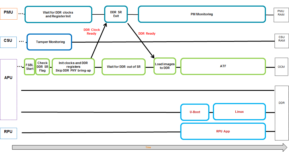
Implementation
On PS-only and System reset, the PMU puts the DDR into self-refresh. While booting after the reset, the PMU takes the DDR out of self-refresh.
On booting, the FSBL needs to know whether the DDR is in self-refresh or not. If the DDR is not in self-refresh, it will initialize the DDR. Otherwise, it will skip over DDR controller and ECC initialization, but wait for the PMU to bring the DDR out of self-refresh, before proceeding to load binaries into the DDR.
To coordinate between the PMU and the FSBL, two bits in the Persistent Global Storage General Storage register 7 (at 0xFFD8006C) are used. The value of this register is retained across software resets. The bits are:
| PGGS-7 register bit | Description |
|---|---|
| Bit 3 | DDR State (1 = in self-refresh, 0 = not in self-refresh) |
| Bit 4 | DDR Controller State (1 = initialized, 0 = not initialized) |
By default, this feature is disabled. User can enable this feature by enabling following build flags during PMUFW and FSBL compilation:
- PMUFW: ENABLE_DDR_SR_WR
- FSBL: XFSBL_ENABLE_DDR_SR
After enabling these build flags PMUFW will put DDR in self-refresh mode during warm restart (PS only or System restart).
Note: For warm-restart scenarios where the PMU GPO is interfacing with external resets the PMU must be loaded prior to FSBL to avoid undesired toggles of the GPO when the psu_init maps it to the MIO.
DDR Context
PMUFW stores DDR controller and PHY register values in PMU RAM before putting DDR in self refresh and restores that register values from PMU RAM after reset.
DDR Calibration
After taking the DDR out of self-refresh, the PMU will trigger some DDR calibration sequences. These sequences will write test data to some DDR memory locations, and the data in those locations will be destroyed. In order to prevent data loss, a block of 4-Kbyte memory in DDR is pre-allocated to save the data in those locations before the reset. After reset, the PMU will restore the data to those locations used for calibration.
The location of this reserved area must satisfy the following conditions:
- Must be in the lower 2 GB address range.
- Must not be touched by the DDR calibration sequences.
- Must not be used to retain data over reset.
Note: One may use the memory locations that are used by Linux because we don't need to retain Linux memory over reset. However, the location must still satisfy the above 3 conditions.
The default reserve location is hard coded in the pm_ddr.c file. Users may change the DDR_RESERVE_ADDR macro in the file to move to a different location.
DDR ECC initialization in FSBL
Enabling ECC (in design) will enable correcting of single bit errors and detection of multiple bit errors.
DDR region need to be written/initialized (after DDRC initialization) before its first read so that the corresponding ECC is valid and to avoid false ECC errors while reading. If ECC is enabled in design then, FSBL will initialize DDR region to avoid ECC errors.
FSBL will skip ECC initialization if DDR is in self refresh mode during warm restart.
Idle and Reset of Peripherals
As explained above, it is necessary to stop/complete any ongoing transaction by any IP or processor of the subsystem before resetting them, otherwise it may lead to hanging of the interconnect and eventually hanging of the entire system. Also to ensure proper operation by the IP after reboot, it is best to reset them and bring them to post bootrom state.PMU firmware implements peripheral idling and resetting for the PS IPs that can be idled / reset during the subsystem reset. The IPs that will be attempted to idled/reset is based on isolation configuration of the Vivado.
Build PMU firmware with the following idling flags to enable subsystem node idling and resetting.
ENABLE_NODE_IDLING
IDLE_PERIPHERALS
Node Reset and Idle
During subsystem restart, the pmu-firmware makes sure that the associated PS peripherals nodes are idled and brought to reset state.
Following is the lists of currently supported PS peripherals that will undergo idle/reset if they are part of subsystem undergoing reset:
- TTC
- Ethernet/EMAC
- I2C
- SD
- eMMC
- QSPI
- USB
- DP
- SATA
Note:
- Refer GPIO reset to PL section to understand the implication of GPIO reset.
- In the case of user invoked reboot of ps-only and system-reset command, PS peripherals are idled prior to invoking resets.
Custom Hooks
PMU firmware does not keep track of PL peripherals, hence there is not reset of idle/reset function implementations available in the pmu-firmware. But it is necessary to treat those peripherals in the same way we treated PS peripheral. One can add a custom hook in the idle_hooks.c file to idle PL peripheral and reset them. This hooks can be called from PmMasterIdleSlaves function in pm_master.c file of pmu firmware.lib/sw_apps/zynqmp_pmufw/src/pm_master.c
@@ -769,6 +769,12 @@ static void PmMasterIdleSlaves(PmMaster* const master)
PmDbg(DEBUG_DETAILED,"%s\r\n", PmStrNode(master->nid));
+ /*
+ * Custom hook to idle PL peripheral before PS peripheral idle
+ */
+
+ Xpfw_PL_Idle_HookBeforeSlaveIdle(master);
+
while (NULL != req) {
u32 usage = PmSlaveGetUsageStatus(req->slave, master);
Node = &&req->slave->node;
@@ -783,6 +789,11 @@ static void PmMasterIdleSlaves(PmMaster* const master)
}
req = req->nextSlave;
}
+
+ /*
+ * Custom hook to idle PL peripheral after PS peripheral idle
+ */
+ Xpfw_PL_Idle_HookAfterSlaveIdle(master);
#endif
}
The Xpfw_PL_Idle_HookBeforeSlaveIdle and Xpfw_PL_Idle_HookAfterSlaveIdle can contain the code to idle the PL peripherals and reset them if necessary. The implementation can either
- Write Axi registers of PL IPs to bring them to idle state and reset
- Implement a signal based handshake where PMU firmware drives the IDLE signal to the PL through GPO and waits on a GPI for acknowledgement from the PL. The signal in the PL is implemented in such a way that it only drives the ACK signal back to PMU firmware after all PL IPs for that subsystem have been idled, all transactions from PS to PL for that subsystem have been completed and all PL IPs for that subsystem have been reset.
Note: Implementation for these custom hooks is not provided by Xilinx.
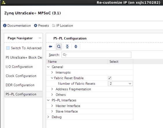
GPIO Reset to PL
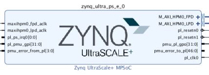
Vivado configuration allows user to enable fabric resets from PS to PL. The figure below shows that with Fabric Reset Enabled and the Number of Fabric Resets set to 2, the Zynq UltracScale+ block outputs pl_resetn0 and pl_resetn1 signals which can be used to drive reset pins of PL components.
The pl_resetn signals are implemented with PS GPIOs. Pl_resetn pins are release after bitstream configuration in software using the function psu_ps_pl_reset_config_data. In the case where a subsystem also uses GPIO for purpose other than reset, the GPIO block is included in the subsystem definition. The image below shows an example of a APU subsystem with GPIO as a slave peripheral.
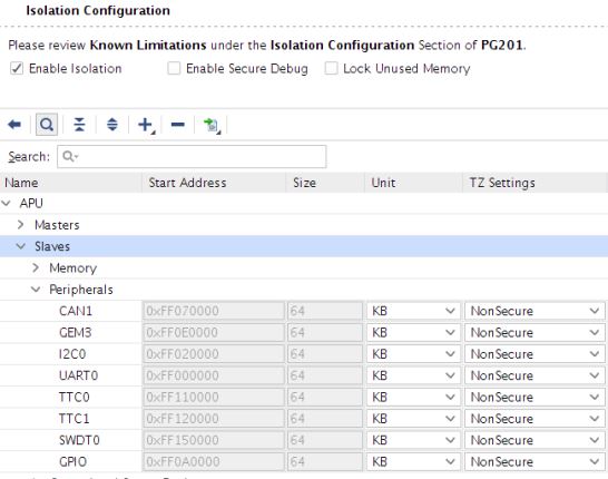
In the case where GPIO is a subsystem slave peripheral, when the subsystem is being restarted, the entire GPIO component will be reset as part of the restart process. Because pl_resetn are implemented with GPIOs, pl_resetn will be forced low during subsystem restart. This behavior may be extremely undesirable if the pl_resent signals are being used to drive PL IPs in subsystems other than the one being reset. For example, if pl_resetn0 drives resets to PL IP for APU subsystem and pl_resetn1 drives PL IPs for RPU subsystem, during APU subsystem restart, both pl_resetn0 and pl_resent1 will be forced into the reset state, consequently, PL IPs in RPU subsystem will be reset which is the wrong behavior since apu-restart is supposed to not effect the running of the RPU subsystem.
This is really a case where GPIO is implicitly shared between the APU and RPU subsystem via pl_resetn signals and since sharing of peripherals are not supported for subsystem restart, pl_resetn causes problems during subsystem reset. The work-around is to skip idling and resetting GPIO peripheral during any subsystem restart even if the component is assigned in the subsystem/isolation configuration.
To skip the GPIO reset during the node Idling and reset, pmu-firmware should be built with following flag:
REMOVE_GPIO_FROM_NODE_RESET_INFO
Recovering from a System Hang
Recovery
In an event of system hang, as indicated by FPD WDT timeout, PMU can be used to carry out a sequence of events to try and recover from the unresponsive condition. By default, when FPD WDt times out, PMU FW will not invoke any type of restart. This is so that user can specify the exact desired behavior. However, Xilinx provides a typical recovery scheme in which PMU firmware monitors the state of APU subsystem using FPD watchdog timer and restart APU (Linux) subsystem if the timer expires, indicating problem with Linux. This scheme is termed recovery and the method of enabling this feature is detailed below.
Since RPU subsystem is managed by Linux via remoteproc, the lifecycle of the RPU subsystem is completely up to Linux. PMU is not involved in deciding when to restart RPU subsystem(s). RPU hang recovery can also be implemented with help of either software or hardware watchdog between APU and RPU subsystems. In that case, the watchdog is configured and handled by Linux but the heartbeats is provided by RPU application(s). The exact method of deciding when to restat RPU is up to the user, watchdog is simply one of many possibilities.
To enable recovery, PMU firmware should be built with error management enable and recovery enabled. Following macros enables the Recovery feature.
ENABLE_EM
ENABLE_RECOVERY
# For 2018.2 and earlier releases:
ZYNQMP_WARM_RESTART=1
# For 2018.3 and later releases:
ZYNQMP_WDT_RESTART=1
Watchdog management
FPD watchdog timer (FPD WDT) is used for monitoring APU state. Software running on APU periodically touch FPD WDT to keep it from timing out. The occurrence of WDT timeout indicates a unexpected condition on the APU which prevents the software from running properly and a APU restart is invoked. FPD WDT is configured by PMU firmware at initialization stage, but is periodically pumped by software running on APU.
The default timeout configured for WDT is 60 seconds and can be changed by RECOVERY_TIMEOUT flag in pmu-fw. When APU subsystem goes into a restart cycle, FPD WDT is kept running to ensure that the restart lands in a clean running state where software running on APU is able to touch the WDT again. Therefore, the timeout for the WDT must be long enough to cover the entire APU subsystem restart cycle to prevent the WDT from timing out in the middle of restart process. It is advisable to start providing the heartbeat as soon as is feasible in Linux. Petalinux's warm restart bsp includes recipe to adds the watchdog management service in init.d.
As FPD WDT is own by PMU-firmware it would be unsafe to use full fledge Linux driver for handling WDT. It is advisable to just pump the hearbeats by writing restart key (0x1999) to restart register (WDT base + 0x8) of the WDT. It can be done through C program daemon or it can be part of bash script daemon. It is recommended to be part of idle thread or similar low priority thread, which if hangs we should consider the subsystem hang.
Below is snippet of the single heartbeat stroke to the FPD WDT from command prompt. This can be included in the bash script which run periodically.
# devmem 0xFD4D0008 32 0x1999
Below is wdt-heartbeat application that periodically provides heartbeat to FPD WDT. For demo purpose this application is launched as daemon. The code from this application can be implemented in appropriate location like Linux's Idle thread.
#include <stdio.h>
#include <sys/mman.h>
#include <fcntl.h>
#include <unistd.h>

#define WDT_BASE                0xFD4D0000
#define WDT_RESET_OFFSET        0x8
#define WDT_RESET_KEY            0x1999

#define REG_WRITE(addr, off, val) (*(volatile unsigned int*)(addr+off)=(val))
#define REG_READ(addr,off) (*(volatile unsigned int*)(addr+off))


void wdt_heartbeat(void)
{
    char *virt_addr;
    int fd;
    int map_len = getpagesize();

    fd = open("/dev/mem", (O_RDWR | O_SYNC));

    virt_addr = mmap(NULL,
            map_len, PROT_READ|PROT_WRITE,
            MAP_SHARED,
            fd,
            WDT_BASE);

    if (virt_addr == MAP_FAILED)
        perror("mmap failed");

    close(fd);

    REG_WRITE(virt_addr,WDT_RESET_OFFSET, WDT_RESET_KEY);

    munmap((void *)virt_addr, map_len);
}

int main()
{
    while(1)
    {
        wdt_heartbeat();
        sleep(2);
    }
    return 0;
}
On expiry of the watchdog, PMU firmware receives and handle the WDT interrupt. PMU firmware idles the subsystem’s master CPU i.e. all A53 cores (see APU Idling) and then carries out APU only restart flow which includes CPU reset, idling and resetting peripherals (see Peripheral Idling) associated to subsystem reset.
Note: If ESCALATION is enabled PMU-firmware will trigger the appropriate restart flow (which can be other than APU only restart) as explained in Escalation section.
APU Idling
Each A53 is idled by taking them to the WFI state. This is done through Arm Trusted Firmware (ATF). For idling CPU, the PMU firmware raises IPI to ATF, which issues software interrupt to each alive A53 core. The respective cores then clears the pending SGI on itself and put itself into WFI.The last core just before going into WFI will issue pm_system_shutdown (PMU Firmware API) to pmu-firmware, which then will do APU only restart flow.
This feature must be enabled in ATF for recovery to work properly. It can be enabled by building ATF with (For 2018.2 and earlier releases) ZYNQMP_WARM_RESTART=1 or (For 2018.3 and later releases) ZYNQMP_WDT_RESTART=1 flag.
Modifying Recovery Scheme
When ENABLE_RECOVERY is turned on, Xilinx provides an recovery implementation in which a FPD WDT timeout results in the invocation of APU subsystem restart. User can easily modify the recovery behavior by modifying the code. Alternatively, an example of PMU FW invoking system-reset on FPD WDT timeout is detailed in AR #96463Escalation
In the event where current recovery could not bring the system back to the working state, the system should escalate to a more severe type of reset on the next WDT expiry in order to try and recovery fully. It is up to the user to decide on the escalation scheme. A commonly used scheme starts with apu-restart on the first watchdog expiration, followed by ps-only reset on the next watchdog expiration, then finally system-reset.
To enable Escalation, PMU firmware should be built with following flags
ENABLE_ESCALATION
Escalation Scheme
Default Scheme
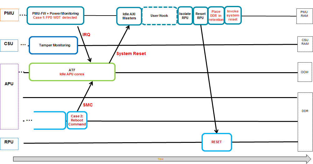
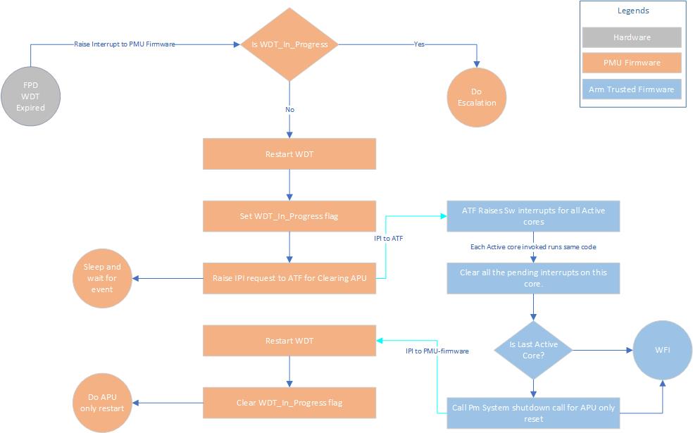
Default escalation scheme checks for the successful pm_system_shutdown call from ATF for APU only restart which happens when ATF is able to successfully idle all active CPUs. If ATF is not successful in idling the active cores (see blue boxes in the flow chart), WDT will time out again with the WDT_in_Progess flag set, resulting in "do escalation". Escalation will trigger System level reset. System level reset is defined as PS only reset if PL is present or System restart if PL is not present.The flowchart below illustrate the flow of the control in case of default escalation scheme
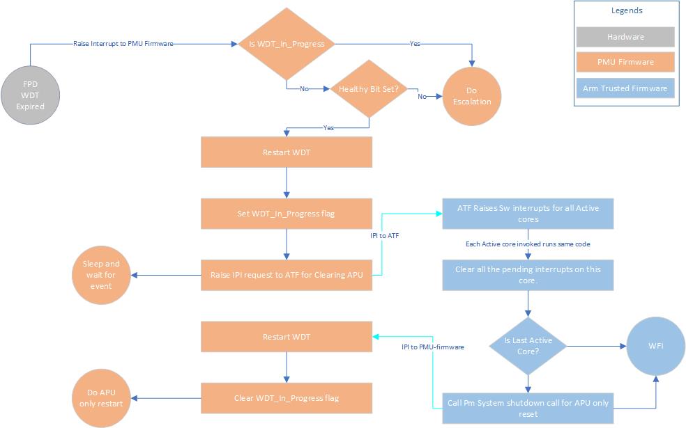
Healthy Bit Scheme
Default scheme for escalation doesn’t guarantee the successful reboot of the system, it just guarantees the successful role of ATF during the recovery to idle the CPU. Consider the scenario in which the FPD_WDT has timed out and apu subsystem restart is called in which ATF is able to successfully make the pm_system_shutdown call. However, apu subsystem restart is far from finished after pm_system_shutdown is called. The restart process can be stuck elsewhere, such as fsbl, u-boot or Linux init state. Suppose that the restart process is stuck in one of the aforementioned tasks, FPD_WDT will expire again, causing the same cycle to be repeated as long as ATF is loaded and functioning. This cycle can continue indefinitely without the system booting back into a clean running state.The Healthy Bit scheme solves this problem. In addition to default scheme, the pmu-firmware checks for a Healthy Bit, which is set by Linux on successful booting. On WDT expiry, if Healthy Bit is set, it indicates that Linux is able to boot into a clean running state, then no escalation is needed. However, if Healthy Bit is not set, that means last restart attempt did not successful boot into Linux and escalation is needed. There is no need to repeat the same type of restart,PMU firmware will escalate and call a system level reset.
Healthy Bit scheme is implemented using the 0th bit of pmu global general storage register (PMU_GLOBAL_GLOBAL_GEN_STORAGE4[0]). PMU firmware clears the bit before starting the recovery or normal reboot and Linux should set this bit to flag a healthy boot.
PMU global registers are accessed through sysfs interface from Linux. So to set the healthy bit from the Linux following command should be executed (or included in the code)
For version 2022.1 and later:
# echo 1 > /sys/devices/platform/firmware:zynqmp-firmware/health_status
For version from 2018.2 to 2021.2:
# echo 1 > /sys/firmware-zynqmp/health_status
# echo "0x20000000 0x20000000" > "/sys/devices/platform/firmware/ggs0"
To enable Healthy Bit based escalation scheme, PMU firmware should be built with following flag
CHECK_HEALTHY_BOOT
Following diagram illustrate the flow of the control in case of Healthy bit escalation scheme
Customizing Recovery and Escalation Scheme
By default, when FPD WDT times out, PMU FW will not invoke any type of restart. While Xilinx has provided predefined RECOVERY and ESCALATION behaviors, users can easily customize different desired schemes.
When FPD_WDT times out, it calls FpdSwdtHandler. FpdSwdtHandler calls XPfw_recoveryHandler if ENABLE_EM is defined. It is otherwise an empty function.
In xpfw_mod_em.c,
#ifdef ENABLE_EM
void FpdSwdtHandler(u8 ErrorId)
{
XPfw_Printf(DEBUG_ERROR,"EM: FPD Watchdog Timer Error (Error ID: %d)\r\n",
ErrorId);
XPfw_RecoveryHandler(ErrorId);
}
#else
void FpdSwdtHandler(u8 ErrorId) { }
Without ENABLE_EM, user can simply update FpdSwdtHandler which will be called at FPD Timeout.
With ENABLE_EM turned on, user needs to update XPfw_recoveryHandler.
Similarly, turning on RECOVERY defines the XPfw_RecoveryHandler (among other things… see xpfw_restart.c). So, unless RECOVERY is turned on, XPfw_ RecoveryHandler is an empty function and nothing will happen when FPD_WDT times out.
RecoveryHandler basically follows the flow chart detailed in the Escalation Scheme section. When FPD_WDT times out, the code follows the progression of orange boxes. If WDT is not already in progress, Restart WDT, Set WDT_In_Progress flag, Raise IPI request to ATF. Then ATF takes over, it Raises Sw interrupt for all active cores, clear pending interrupts, etc(see blue boxes). Essentially, PMU restarts and kicks the WDT, then sends a request to ATF. ATF cleanly idles all four APUs and when they all get to WFI (Last Active Core is true), ATF issues Pm System Shutdown with APU subsystem as argument back to PMU. When PMU gets this command, it invokes APU subsystem restart.
If ENABLE_ESCALATION is not set, the code never takes the “Do Escalation” path. If the RecoveryHandler hangs for some reason (for example, something went wrong and apu can’t put all four to wfi), it just keep retrying apu restart or hang forever. When ENABLE_ESCLATION is on, if anything goes wrong during execution of the flowchart, it will look like WDT is still in progress (since clear WDT_in_progress fla happens only as the last step), Do Escalation will call SYSTEM_RESET instead of trying apu-restart again and again.
To customize recovery and escalation behavior, use the provided XPfw_recoveryHandler as a template to provide a customized XPfw_recoveryHandler function.
Building Software
All the software components are built and packaged by Xilinx Petalinux tool.Build Flag for Restart Solution
Following are the build time flags which are not set by default and can alter the behavior of the restart in zynq ultrascale plus MPSoC.
| Component | Flag name | Descriptions | Dependency |
| PMU Firmware | ENABLE_EM | Enable error management and provide WDT interrupt handling. This is not directly related to restart solution but needed for recovery. | - |
| ENABLE_RECOVERY | Enable Recovery during WDT expiry | For 2018.2 and earlier releases, ENABLE_EM + ZYNQMP_WARM_RESTART=1 in ATF For 2018.3 and later releases, ENABLE_EM + ZYNQMP_WDT_RESTART=1 in ATF | |
| ENABLE_ESCALATION | Allow escalation on failure of boot or recovery | ENABLE_RECOVERY | |
| CHECK_HEALTHY_BOOT | Use Healthy bit to determine escalation | ENABLE_ESCALATION | |
| IDLE_PERIPHERALS ENABLE_NODE_IDLING | Both the flags should be used together to allow pmu-fw to attempt peripherals node idling (and reset). | BOTH of these flags should be enabled together. | |
| REMOVE_GPIO_FROM_NODE_RESET_INFO | Skips GPIO from the node idling and resetting list. This is needed when the system is using GPIO to provide reset (or similar) signals to PL or other peripherals outside current subsystem. If this flag is set, GPIO will not be reset. | ENABLE_NODE_IDLING | |
| DISABLE_UART_IDLING | Skips UART idling. | All the flags mentioned above | |
| ATF | For 2018.2 and earlier releases, ZYNQMP_WARM_RESTART=1 For 2018.3 and later releases, ZYNQMP_WDT_RESTART=1 | Enable WARM RESTART recovery feature in ATF that allow the CPU idling triggered from PMU firmware | - |
| FSBL | FSBL_PROT_BYPASS | Skip XMPU/XPPU based configuration for system except for DDR and OCM. | - |
| Linux | CONFIG_SRAM | Needed for Remoteproc to work for load RPU images in the TCM |
Modifying Component Recipes
Each component's recipe can be changed to either include the build time compilation flags or to include patches for custom code modification/addition.Petalinux provides meta-user yocto based layer for user specific modifications. The layer can be found in project
PMU Firmware
User specific recipe for pmu firmware can be found in the project @ for 2021.2 and earlier releases, project-spec/meta-user/recipes-bsp/pmu/pmu-firmware_%.bbappend or for 2022.1 and later releases, project-spec/meta-user/recipes-bsp/embeddedsw/pmu-firmware_%.bbappend (if doesn't exist please create this file @ this path).
The pmu-fw code can be modified by patches against embeddedsw GitHub repo. Location for the source code is embeddedsw/tree/master/lib/sw_apps/zynqmp_pmufw.
The patches should be copied to project-spec/meta-user/recipes-bsp/pmu/files directory and the same patch names should be added pmu-firmware_%.bbappend file.
Example:
If a patch name is my_changes.patch (against pmu-firmware source) is to be added and all the flags explained in table above has to be enabled (set) then for 2021.2 and earlier releases, project-spec/meta-user/recipes-bsp/pmu/pmu-firmware_%.bbappend or for 2022.1 and later releases, project-spec/meta-user/recipes-bsp/embeddedsw/pmu-firmware_%.bbappend file will look like as below
#For 2021.2 and earlier releases
YAML_COMPILER_FLAGS_append =  " -O2 -DENABLE_EM -DENABLE_RECOVERY -DENABLE_ESCALATION -DENABLE_NODE_IDLING -DREMOVE_GPIO_FROM_NODE_RESET_INFO -DCHECK_HEALTHY_BOOT -DIDLE_PERIPHERALS"

FILESEXTRAPATHS_prepend := "${THISDIR}/files:"

SRC_URI_append = " file://my_changes.patch"

#For 2022.1 and later releases
YAML_COMPILER_FLAGS:append =  " -O2 -DENABLE_EM -DENABLE_RECOVERY -DENABLE_ESCALATION -DENABLE_NODE_IDLING -DREMOVE_GPIO_FROM_NODE_RESET_INFO -DCHECK_HEALTHY_BOOT -DIDLE_PERIPHERALS"

FILESEXTRAPATHS:prepend := "${THISDIR}/files:"

SRC_URI:append = " file://my_changes.patch"
FSBL
User specific recipe for fsbl can be found in the project @ for 2021.2 and earlier releases, project-spec/meta-user/recipes-bsp/fsbl/fsbl_%.bbappend or for 2022.1 and later releases, project-spec/meta-user/recipes-bsp/embeddedsw/fsbl_%.bbappend (if doesn't exist please create this file @ this path).The fsbl code can be modified by patches against embeddedsw GitHub repo. Location for the source code is embeddedsw/tree/master/lib/sw_apps/zynqmp_fsbl.
The patches should be copied to project-spec/meta-user/recipes-bsp/fsbl/files directory and the same patch names should be added fsbl_%.bbappend file.
Example:
If a patch name is my_changes.patch (against fsbl source) is to be added and all the flags explained in table above has to be enabled (set) then the modified for 2021.2 and earlier releases, project-spec/meta-user/recipes-bsp/fsbl/fsbl_%.bbappend or for 2022.1 and later releases, project-spec/meta-user/recipes-bsp/embeddedsw/fsbl_%.bbappend file will look like as below (Note:XPS_BOARD_ZCU102 flag was already existing).
#For 2021.2 and earlier releases
YAML_COMPILER_FLAGS_append = " -DXPS_BOARD_ZCU102 -DFSBL_PROT_BYPASS"

FILESEXTRAPATHS_prepend := "${THISDIR}/files:"

SRC_URI_append = " file://my_changes.patch"

#For 2022.1 and later releases
YAML_COMPILER_FLAGS:append = " -DXPS_BOARD_ZCU102 -DFSBL_PROT_BYPASS"

FILESEXTRAPATHS:prepend := "${THISDIR}/files:"

SRC_URI:append = " file://my_changes.patch"
ATF
User specific recipe for ATF can be found in the project @ project-spec/meta-user/recipes-bsp/arm-trusted-firmware/arm-trusted-firmware_%.bbappend (if doesn't exist please create this file @ this path).Git repository for ATF : https://github.com/Xilinx/arm-trusted-firmware
Example:
To add warm restart flag to ATF, project-spec/meta-user/recipes-bsp/arm-trusted-firmware/arm-trusted-firmware_%.bbappend file will look like as below
#
# Enabling warm restart feature
#
# For 2018.2 and earlier releases
EXTRA_OEMAKE_append = "  ZYNQMP_WARM_RESTART=1"
# From 2018.3 to 2021.2 releases
EXTRA_OEMAKE_append = "  ZYNQMP_WDT_RESTART=1"
# For 2022.1 and later releases
EXTRA_OEMAKE:append = "  ZYNQMP_WDT_RESTART=1"
Linux
There are many ways to add /modify Linux configuration. Please refer Petalinux userguide for the same.User specific recipe for Linux kernel can be found in the project @ project-spec/meta-user/recipes-kernel/linux/linux-xlnx_%.bbappend (if doesn't exist please create this file @ this path).
Git repository for Linux: https://github.com/Xilinx/linux-xlnx
Example:
To add SRAM config to Linux, create a bsp.cfg file @ project-spec/meta-user/recipes-kernel/linux/linux-xlnx/bsp.cfg
CONFIG_SRAM=y
Add this file in the bbapend file of Linux @ project-spec/meta-user/recipes-kernel/linux/linux-xlnx_%.bbappend which will look like as below
SRC_URI += "file://bsp.cfg"

#For 2021.2 and earlier releases
FILESEXTRAPATHS_prepend := "${THISDIR}/${PN}:"

#For 2022.1 and later releases
FILESEXTRAPATHS:prepend := "${THISDIR}/${PN}:"
Modifying Platform Specific Build Flags
YAML_COMPILER_FLAGS:append:xilinx-k26-som = "-DENABLE_SCHEDULER
Modifying Device Tree
User specific recipe for device tree can be found in the project @ project-spec/meta-user/recipes-bsp/device-tree/device-tree-generation_%.bbappend, with following contents
#For 2021.2 and earlier releases
SRC_URI_append ="\
    file://system-user.dtsi \
"
FILESEXTRAPATHS_prepend := "${THISDIR}/files:"

#For 2022.1 and later releases
SRC_URI:append ="\
    file://system-user.dtsi \
"
FILESEXTRAPATHS:prepend := "${THISDIR}/files:"
The content of system-user.dtsi in project-spec/meta-user/recipes-bsp/device-tree/files directory is
/include/ "system-conf.dtsi"
/ {
};
This file can be modified to extend the device tree functionality by adding /removing / modifying the dts nodes.
Example: Adding DT node(s) [ remoteproc RPU split mode]
The overlay dtsi(s) can be added in files/ directory (remember to update bbappend file accordingly) and included in system-user.dtsi.
For adding remoteproc related entries to enable RPU subsystem load / unload /restart; lets add new overlay file called remoteproc.dtsi
Note: this is for split mode, check open amp documentation for lockstep and other possible configurations.
File: remoteproc.dtsi
/ {

    reserved-memory {

        #address-cells = <2>;

        #size-cells = <2>;

        ranges;

        rproc_0_reserved: rproc@3ed000000 {

            no-map;

            reg = <0x0 0x3ed00000 0x0 0x1000000>;

        };

    };


    power-domains {

        pd_r5_0: pd_r5_0 {

            #power-domain-cells = <0x0>;

            pd-id = <0x7>;

        };

        pd_r5_1: pd_r5_1 {

            #power-domain-cells = <0x0>;

            pd-id = <0x8>;

        };

        pd_tcm_0_a: pd_tcm_0_a {

            #power-domain-cells = <0x0>;

            pd-id = <0xf>;

        };

        pd_tcm_0_b: pd_tcm_0_b {

            #power-domain-cells = <0x0>;

            pd-id = <0x10>;

        };

        pd_tcm_1_a: pd_tcm_1_a {

            #power-domain-cells = <0x0>;

            pd-id = <0x11>;
        };

        pd_tcm_1_b: pd_tcm_1_b {

            #power-domain-cells = <0x0>;

            pd-id = <0x12>;

        };

    };


    amba {

        r5_0_tcm_a: tcm@ffe00000 {

            compatible = "mmio-sram";

            reg = <0x0 0xFFE00000 0x0 0x10000>;

            pd-handle = <&&pd_tcm_0_a>;

        };

        r5_0_tcm_b: tcm@ffe20000 {

            compatible = "mmio-sram";

            reg = <0x0 0xFFE20000 0x0 0x10000>;

            pd-handle = <&&pd_tcm_0_b>;

        };

        r5_1_tcm_a: tcm@ffe90000 {

            compatible = "mmio-sram";

            reg = <0x0 0xFFE90000 0x0 0x10000>;

            pd-handle = <&pd_tcm_1_a>;

        };

        r5_1_tcm_b: tcm@ffeb0000 {

            compatible = "mmio-sram";

            reg = <0x0 0xFFEB0000 0x0 0x10000>;

            pd-handle = <&pd_tcm_1_b>;

        };


        elf_ddr_0: ddr@3ed00000 {

            compatible = "mmio-sram";

            reg = <0x0 0x3ed00000 0x0 0x40000>;

        };


        elf_ddr_1: ddr@3ed40000 {

            compatible = "mmio-sram";

            reg = <0x0 0x3ed40000 0x0 0x40000>;

        };


        test_r50: zynqmp_r5_rproc@0 {

            compatible = "xlnx,zynqmp-r5-remoteproc-1.0";

            reg = <0x0 0xff9a0100 0x0 0x100>, <0x0 0xff340000 0x0 0x100>, <0x0 0xff9a0000 0x0 0x100>;

            reg-names = "rpu_base", "ipi", "rpu_glbl_base";

            dma-ranges;

            core_conf = "split0";

            sram_0 = <&r5_0_tcm_a>;

            sram_1 = <&r5_0_tcm_b>;

            sram_2 = <&elf_ddr_0>;

            pd-handle = <&pd_r5_0>;

            interrupt-parent = <&gic>;

            interrupts = <0 29 4>;


        } ;


        test_r51: zynqmp_r5_rproc@1 {

            compatible = "xlnx,zynqmp-r5-remoteproc-1.0";

            reg =<0x0 0xff9a0200 0x0 0x100>, <0x0 0xff340000 0x0 0x100>, <0x0 0xff9a0000 0x0 0x100>;

            reg-names = "rpu_base", "ipi", "rpu_glbl_base";

            dma-ranges;

            core_conf = "split1";

            sram_0 = <&r5_1_tcm_a>;

            sram_1 = <&r5_1_tcm_b>;

            sram_2 = <&elf_ddr_1>;

            pd-handle = <&pd_r5_1>;

            interrupt-parent = <&gic>;

            interrupts = <0 29 4>;


        } ;


    };

};
Now include this node in system-user.dtsi
/include/ "system-conf.dtsi"
/include/ "remoteproc.dtsi"
/ {
};
For information on OpenAMP and remoteproc please refer OpenAmp wiki page.
Example: Removing DT node(s) [ PL node]
It is necessary to remove PL nodes, which are not accessed or dependent on APU subsystem, from the device tree.Again we can modify system-user.dtsi in project-spec/meta-user/recipes-bsp/device-tree/files to remove specific node or property.
for example, if we are willing to remove axi-dma node from the dts, then system-user.dtsi can be modified as follow:
/include/ "system-conf.dtsi"
/include/ "remoteproc.dtsi"
/ {

/delete-node/axi-dma;

};
Related content
© Copyright 2019 - 2022 Xilinx Inc. Privacy Policy