PMU Firmware
- Confluence Wiki Admin (Unlicensed)
- Bhatt, Madhav
- Harsha Harsha (Unlicensed)
This page provides information related to the Zynq UltraScale+ MPSoC Platform Management Unit (PMU). The PMU controls the power-up, reset, and monitoring of resources within the system.
Table of Contents
Overview of PMU Firmware
The Platform Management Unit (PMU) in Zynq MPSoC has a Microblaze with 32 KB of ROM and 128 KB of RAM. The ROM is pre-loaded with PMU Boot ROM (PBR) which performs pre-boot tasks and enters a service mode. For more details on PMU, PBR and PMUFW load sequence, refer to Platform Management Unit (Chapter-6) in Zynq MPSoC TRM (UG1085). PMU RAM can be loaded with a firmware (PMU Firmware) at run-time and can be used to extend or customize the functionality of PMU. Some part of the RAM is reserved for PBR, leaving around 125.7 KB for PMU Firmware.Here is the memory layout of PMU RAM:

The PMU Firmware provided in Vitis, comes with a default linker script which aligns with this memory layout and there is no specific customization required from user.
Modules
PMU Firmware is designed to be modular and enables adding new functionality in the form of modules. Each functionally distinct feature is designed in as a module, so that PMUFW can be configured to include only the required functionality for a user application. This type of modular design allows easy addition of new features and as well as optimizes memory footprint by disabling unused modules.All the common functions that may be required by the modules are organized as separate libraries in PMUFW with APIs clearly specified. The included APIs in PMU Firmware are given below:
These APIs can be used by the modules in PMUFW to perform the specified actions as required.
Each module can be provided with three handlers which are called in during the respective phases as described below:
| Module Handler | Purpose | API for Registering the Handler | execution context |
| Init | Called during the init of the core to configure the module, register for events or add scheduler tasks. This can be used to load the configuration data into the module if required. | XPfw_CoreSetCfgHandler(const XPfw_Module_t *ModPtr, XPfwModCfgInitHandler_t CfgHandler); | StartUp |
| Event Handler | Called when an event occurs (module should have registered for this event, preferably during the init phase | XPfw_CoreSetEventHandler(const XPfw_Module_t *ModPtr, XPfwModEventHandler_t EventHandler); | Interrupt |
| IPI Handler | Called when an IPI message with respective module-id arrives | XPfw_CoreSetIpiHandler(const XPfw_Module_t *ModPtr, XPfwModIpiHandler_t IpiHandler, u16 IpiId); | Interrupt |
Inter-Processor Interrupts(IPI) Handling in PMUFW
PMU has 4 Inter-Processor Interrupts(IPI) assigned to it and one set of buffers. By default, PMUFW uses IPI-0 and associated buffers for all message exchange with other processors on the SoC. PMUFW uses IPI driver to send and receive messages. An IPI manager layer is implemented over the driver and it takes care of dispatching the IPI message to the registered module handlers based on IPI ID in the first word of the message. The message format for IPI is given below:| Word | Content | Description |
| 0 | Header | <target_module_id, api_id> |
| 1 | PAYLOAD | Module dependent payload |
| 2 | ||
| 3 | ||
| 4 | ||
| 5 | ||
| 6 | RESERVED | RESERVED – for future use |
| 7 | Checksum |
IPI-1 is used for the callbacks from PMU to other masters and for communication initiated by PMUFW.
Currently, PM and EM modules use IPIs and this can be taken as reference for implementing custom modules which require IPI messaging.
Building PMU Firmware using Vitis
For tips configuring PMU firmware builds in PetaLinux see PetaLinux Yocto Tips.
- Open Vitis
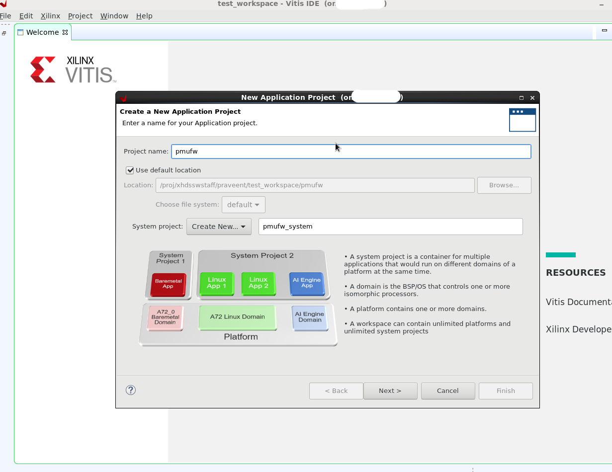
- Create a new application with File->New→Application Project...:
- Enter project name and click on Next. Eg: pmufw
- Select platform as "zcu102" from "Create a new platform from hardware (XSA)" tab options. Click on Next

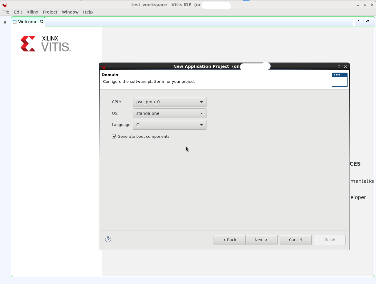
- Now select the domain option as below and click on next
- CPU: psu_pmu_0
- OS: standalone
- Language: C
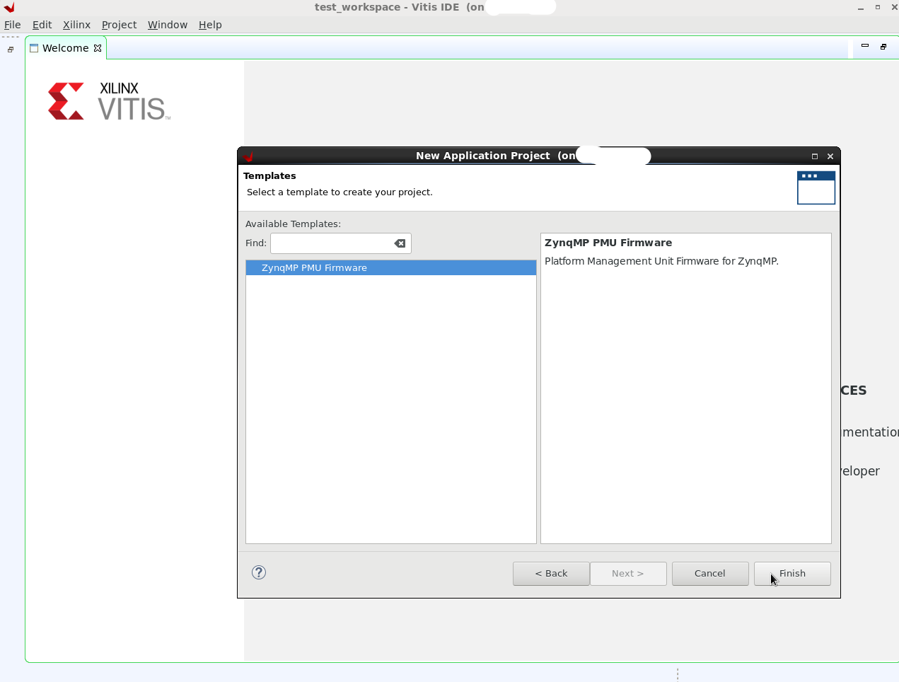
- Select "ZynqMP PMU Firmware" template from Templates list and click on Finish.
- After this, PMU project will be created. Right click on the project and select "Build Project" to build PMU Firmware.
- Enter project name and click on Next. Eg: pmufw
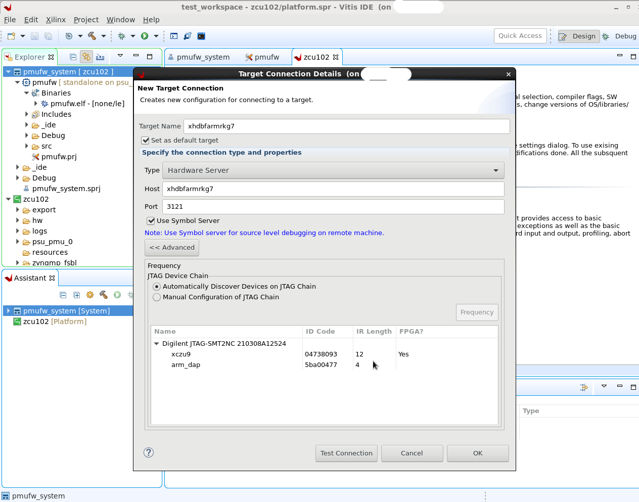
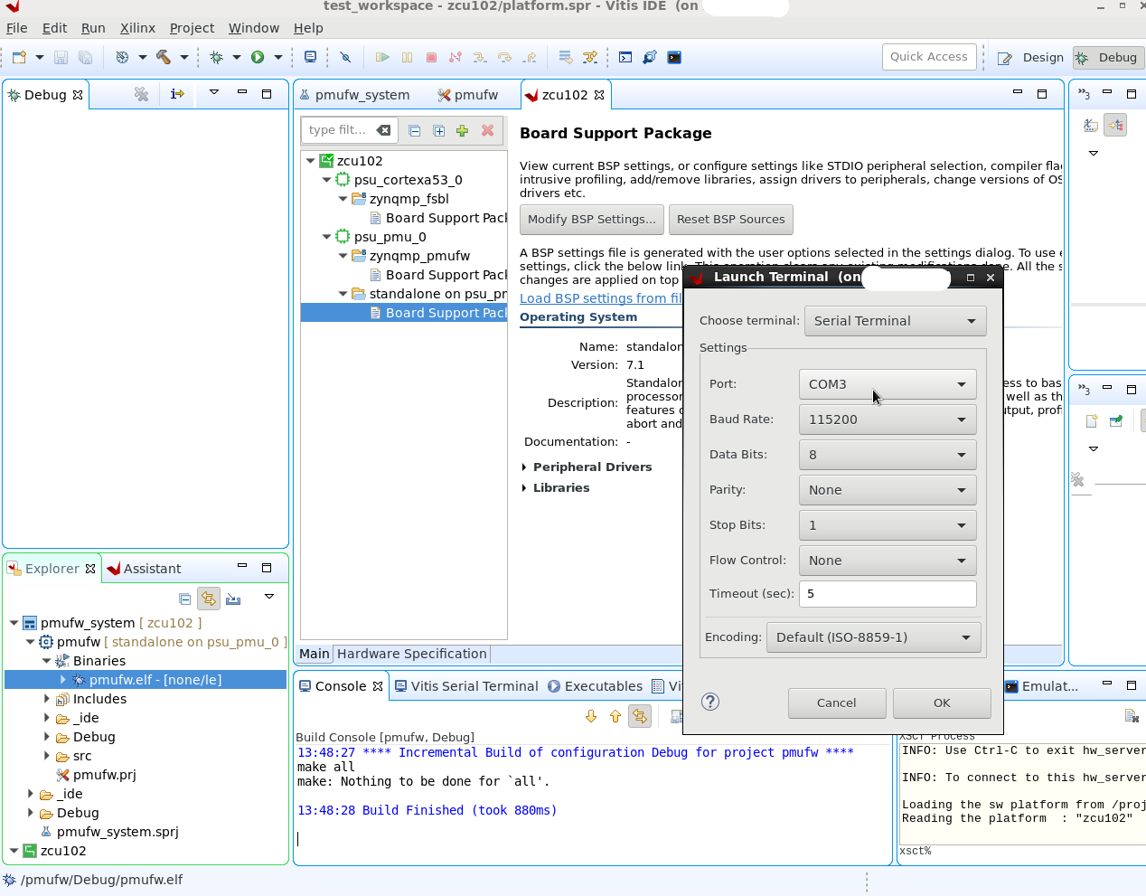
- Connect to the local board and test the connection. You should see a pop up showing that the connection was established successfully.
Connect to the COM port on the terminal to view the UART prints.
IMPORTANT
PMUFW uses psu_uart_0 as default STDOUT. This can be changed to other UARTs using the "Modify BSP Settings" dialogue. To enable debug prints from PMUFW, add DEBUG_MODE and/or XPFW_DEBUG_DETAILED to the defined symbols list in build settings dialog.
Additionally, Xilinx tools default to loading PMUFW from CBR in which case any early/init prints will not be seen. See Using FSBL to load PMUFW for more details.
Attention: When PMUFW logging is enabled, power management for the logging UART port will be disabled. Because of that, some system-wide power management operations will also be affected (e.g. suspend/resume operations may not work properly.) Therefore, PMUFW logging should be enabled only when necessary.
- On XSCT Console, Connect to the board and Run the PMU firmware.
- View the PMU firmware prints on the Terminal console
Debugging PMU FW using Vitis
PMU FW will be built with -Os and LTO optimizations by default.
If the user need to disable the optimization (for debugging), two things need to be done:
Since removing optimization results in increase of code size and can result in not being able to build PMU FW, some of the features that the user don’t use, need to be disabled by removing build flags from project settings. And to further disable some features, it can be disabled in xpfw_config.h file of PMU FW
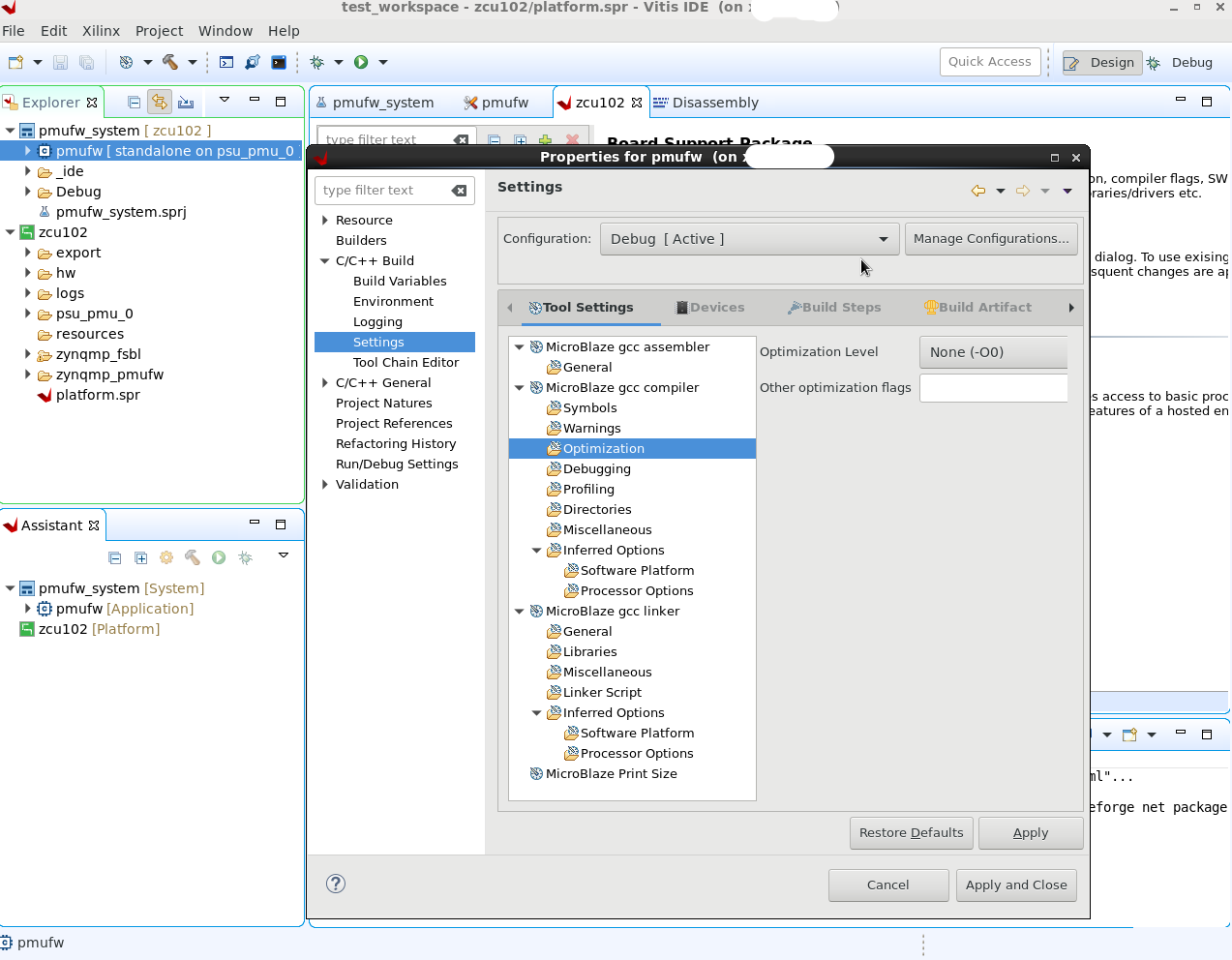
To disable/modify Optimizations, below changes need to be done:
PMU FW application: In "Miscellaneous" section, need to remove/modify highlighted options below:

It has to be noted that the compiler “Optimization” screen in Vitis cannot sense the optimization selected through “Miscellaneous” flags screen (above). This means “Optimization” screen still shows “-O0”, which can be misleading to the users (as shown below).
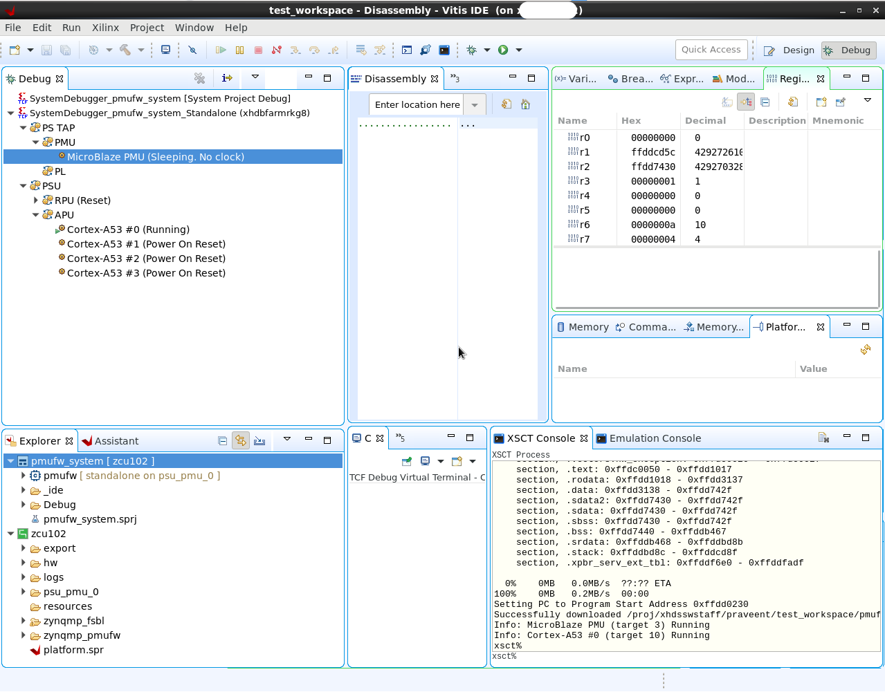
Below are the steps to debug PMU FW application using Vitis:
- Right click on the application to "Debug As" and click on “Debug Configurations”.
- Right click on System Debugger and Click "New". You get a "New Configuration". Click on Debug.

- You will now see the debug perspective and PMU firmware will run.
- Place the break points to control the flow and rerun for debugging.
Loading PMU Firmware in JTAG boot mode
From 2017.1, PM operations depend on the configuration object loaded by FSBL. So it is mandatory to load PMU FW before loading FSBL. This is taken care in device boot modes, but in JTAG boot mode, user need to specifically ensure this.Following are the steps for JTAG boot mode:
- For Silicon v3.0 and above, PMU Microblaze is not visible in xsdb. Hence disable security gates to view PMU Microblaze
- Load PMU FW and run
- Load FSBL and run
- Continue with U-Boot/Linux/user specific application
#Disable Security gates to view PMU MB target
targets -set -filter {name =~ "PSU"}
mwr 0xffca0038 0x1ff
after 500

#Load and run PMU FW
targets -set -filter {name =~ "MicroBlaze PMU"}
dow xpfw.elf
con
after 500

#Reset A53, load and run FSBL
targets -set -filter {name =~ "Cortex-A53 #0"}
rst -processor
dow fsbl_a53.elf
con

#Give FSBL time to run
after 5000
stop

#Other SW...
dow u-boot.elf
dow bl31.elf
con
Loading PMU Firmware in SD boot mode
Note: When PMUFW is loaded in a non-JTAG Boot mode on a 1.0 Silicon, an error message "Error: Unhandled IPI received" may be logged by PMUFW at startup, which can be safely ignored. This is due to the IPI0 ISR not being cleared by PMU ROM which is fixed in 2.0 and later versions of Silicon.
PMU Firmware can be loaded by either FSBL or by CSU BootROM (CBR). Both these flows are supported by Xilinx. PMU Firmware loading by CBR will be needed in the cases where the customer board has an onboard regulator that needs to be programmed to bring up the boot processor's power rail. Loading PMU Firmware using FSBL has these benefits: (i) Possible quick boot time, when PMUFW is loaded after bit-stream, (ii) In use cases where the user want two BIN files - stable and up-gradable, PMUFW can be part of the up-gradable (by FSBL) image.
Using FSBL to load PMU FW
Note: This method of loadind PMUFW (versus loading by CBR) is necessary to see any early prints issued by PMUFW during initialization.
- We already have pmufw.elf with us. ( See building PMU FW at the top of this page)
- Build an FSBL in the Vitis for A53. ( R5 can also be used)
- Create a hello_world example for A53. Right Click on the "hello_world example" project and select "Create a boot image"
- Create a new bif file. Choose
- Architecture : ZynqMP
- You will see A53 fsbl and hello_world example by default in partitions. We need pmufw too.
- Click on Add, then provide pmufw.elf path. Also Partition type: datafile, Destination device : PS, Destination CPU : PMU
- Click OK.
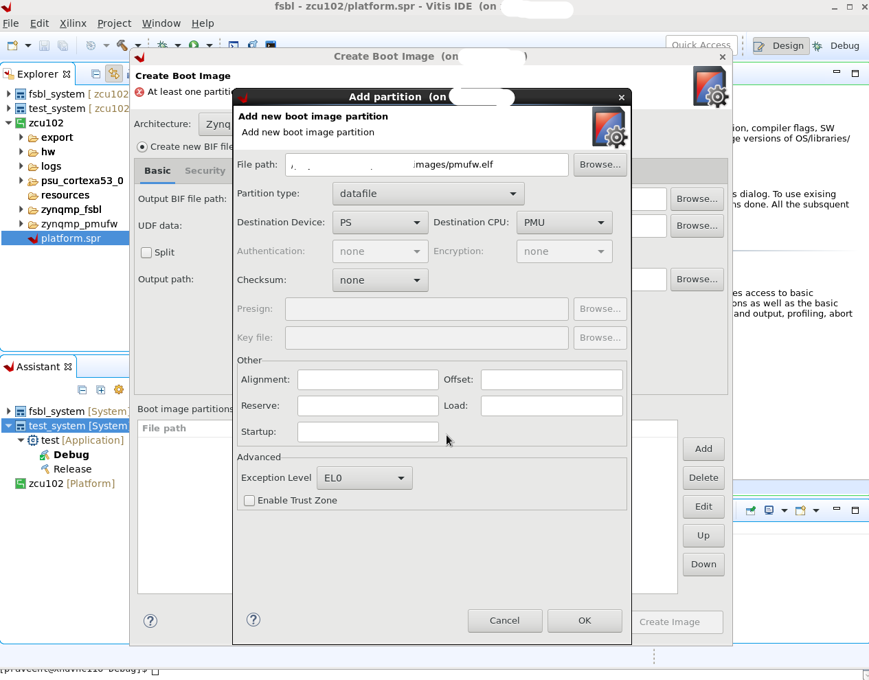
- After adding pmufw as partition. Click on pmufw partition and click UP bottom.
- Make sure partition order
- A53 fsbl
- pmufw
- hello world App
- Click on Create Image. You will see BOOT.bin created in a new folder "bootimage" in your example project.
- View the .BIF file to confirm the partition order.
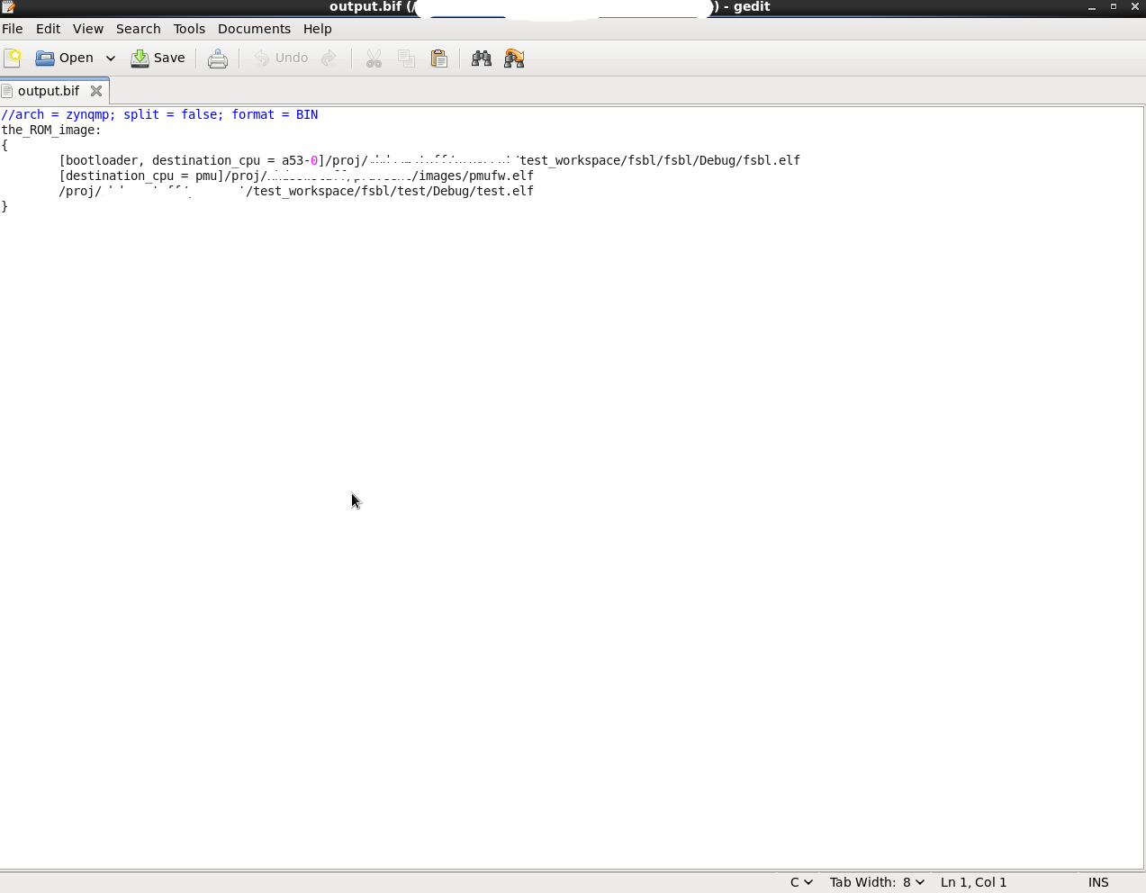
- Now copy this BOOT.bin into SD card.
- Boot the ZCU102 board in SD boot mode. You can see the fsbl -> pmufw ->hello_world example prints in a sequence.
Using CBR to load PMU FW
Note: When PMUFW is loaded by CBR, it is executed prior to FSBL. So the MIOs, Clocks and other initializations are not done at this point and this means that the PMUFW banner and other prints may not be seen prior to FSBL.
Post FSBL execution, the PMUFW prints can be seen as usual.
- To make CBR load pmufw, we just need to change the BOOT.bin boot partitions.
- Now steps listed above (1 -> 3) are same.
- Create a new bif file. Choose
- Architecture : ZynqMP
- You will see A53 fsbl and hello_world example by default in partitions. We need pmufw too.
- Click on Add, then provide pmufw.elf path. Also Partition type: pmu (loaded by bootrom).
- Click OK.

- Click on Create Image. You will see BOOT.bin created in a new folder "bootimage" in your example project.
- You can also view .BIF to confirm the partition order.

- Now copy this BOOT.bin into SD card.
- Boot the ZCU102 board in SD boot mode. You can see the pmufw -> fsbl ->hello_world example prints in a sequence.
PMU FW Build Flags
| Flag | Description | Requires these flags/build options to be enabled | Default setting |
| XPFW_DEBUG_DETAILED | Enables detailed debug prints in PMU Firmware Additionally, see Using FSBL to load PMUFW regarding necessary configuration to see early prints during initialization. | Disabled | |
| PM_LOG_LEVEL | This enables print based debug functions for PM module. Possible values are:
Higher numbers include the debug scope of lower number, i.e: enabling 3 (warnings) also enables 1 (alerts) and 2 (errors) Additionally, see Using FSBL to load PMUFW regarding necessary configuration to see early prints during initialization. | Disabled | |
| ENABLE_EM | Enables Error Management Module | ENABLE_SCHEDULER | Disabled |
| ENABLE_ESCALATION | Enables escalation of sub-system restart to SRST/PS-Only if the first restart attempt fails | ENABLE_RECOVERY | Disabled |
| ENABLE_RECOVERY | Enables WDT based restart of APU sub-system | ENABLE_EM, ENABLE_SCHEDULER, ENABLE_PM | Disabled |
| ENABLE_NODE_IDLING | Enables idling and reset of nodes before force shutdown of a sub-system | Disabled | |
| ENABLE_PM | Enables Power Management Module | Enabled | |
| ENABLE_SCHEDULER | Enables Scheduler Module | Enabled | |
| ENABLE_WDT | Enables WDT based restart functionality for PMU using CSU WDT | ENABLE_SCHEDULER, ENABLE_EM | Disabled |
| ENABLE_CUSTOM_MOD | Enables custom module which is a placeholder for user | Disabled | |
| ENABLE_STL | Enables STL Module | Disabled | |
| ENABLE_RTC_TEST | Enables RTC Event Handler Test Module | Disabled | |
| ENABLE_SAFETY | Enables CRC calculation for IPI messages | Disabled | |
| ENABLE_FPGA_LOAD | Enables FPGA bitstream loading | ENABLE_PM | Enabled |
| ENABLE_SECURE | Enables security features | ENABLE_PM | Enabled |
| XPU_INTR_DEBUG_PRINT_ENABLE | Enables debug prints for XMPU/XPPU error handling see Using FSBL to load PMUFW regarding necessary configuration to see early prints during initialization. | ENABLE_EM | Disabled |
| DEBUG_MODE | Enable debug logging and prints See Using FSBL to load PMUFW regarding necessary configuration to see early prints during initialization. | Disabled | |
| DEBUG_CLK | Enables dumping clock and PLL state functions | ENABLE_PM | Disabled |
| DEBUG_PM | Enables debug functions for PM | ENABLE_PM | Disabled |
| IDLE_PERIPHERALS | Enables idling peripherals before PS or System reset | ENABLE_PM | Disabled |
| ENABLE_POS | Enables Power Off Suspend feature | ENABLE_PM | Disabled |
| EFUSE_ACCESS | Enables eFuse access feature | ENABLE_PM | Disabled |
| ENABLE_MOD_ULTRA96 | Enable power button functionality for ULTRA96 board | ENABLE_PM, ENABLE_SCHEDULER | Disabled |
| ENABLE_SMMU | Bypass SMMU functionality in the firmware during suspend and rewoke the same when resume. | Disabled | |
| PMU_MIO_INPUT_PIN | Enables board shutdown related code | Disabled | |
| EXT_RESET_MIO_PIN_VAL | Board external reset MIO pin (32-37). For K26 and K24 by default it is configured as 35. | Disabled | |
| EXT_RESET_MIO_PIN_STATE_VAL | Board external reset MIO pin active state (0-1). | Disabled |
Note: To enable the platform specific build flag please refer below:
Zynq UltraScale+ MPSoC Restart solution#ModifyingPlatformSpecificBuildFlags
Power Management in PMU FW
Zynq MPSoC Power Management framework is based on an implementation of the Embedded Energy Management Interface (EEMI). This framework allows software components running across different processing units (PUs) on a chip or device to issue or respond to requests for power management.PM Configuration Object
The configuration object is a binary data object used to allow updating data structures in the PMU firmware power management module at boot time. The configuration object must be copied into memory by a processing unit on the Zynq UltraScale+ MPSoC. The memory region containing the configuration object must be accessible by the PMU.The configuration object specifies:
- List of masters available in the system
- All the slave nodes the master is currently using and current requirement of the master for the slave configuration
- All the slave nodes the master is allowed to use and default requirement of the master for the slave configuration
- For each power node, which masters are allowed to request/release/power down
- For each reset line, which masters are allowed to request the change of a reset line value
- Which shutdown mode the master is allowed to request and shutdown timeout value for the master
- Which masters are allowed to set configuration after the configuration is already set upon the system boot by the FSBL
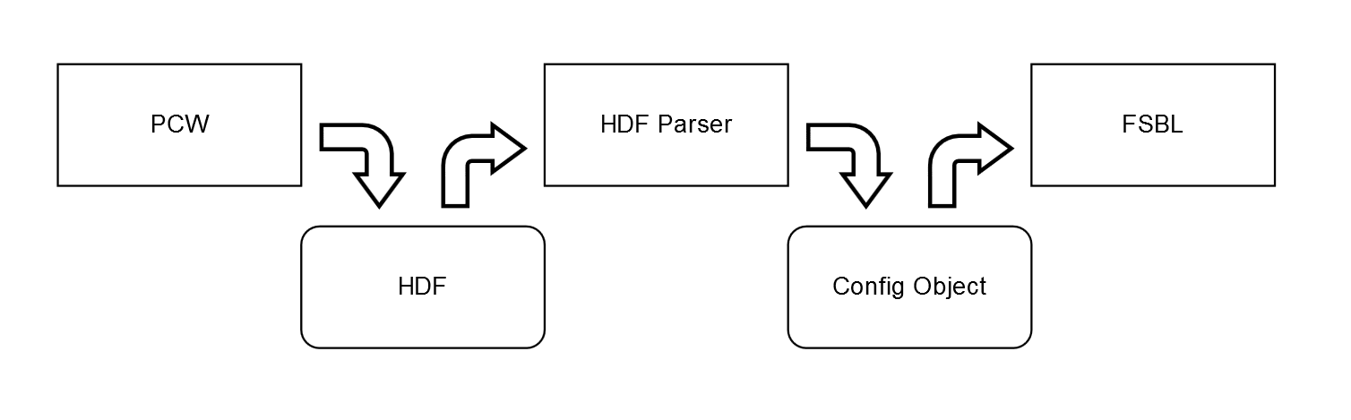
PM Configuration Object Generation
PM Configuration Object is generated as part of XilPM library which is included in A53/R5 FSBL BSP. The PM Configuration Object generation is as follows:- The user specifies their custom PM framework Configuration using the PCW tool
- PCW generates the HDF file
- At build time, the HDF Parser parses the HDF file and insert the config object into the FSBL code
- Open Vitis.
- Click on File -> New -> Application Project. "New Project" window will appear
- Enter project name and click on Next. Eg: test
- Select platform as "zcu102" from "Create a new platform from hardware (XSA)" tab options. Click on Next
- Now select the domain option as below and click on next
- CPU: psu_cortexa53_0
- OS: standalone
- Language: C
- Select "Hello World" template application. Click Finish.
- Click on "Modify BSP settings". BSP settings window appears as below. Select "xilpm" library and click on "Ok"

- Now the BSP and application will get regenerated with xilpm library.
- Now configuration object is generated as part of xilpm library. To verify the same, please check bsp -> psu_cortexa53_0 -> libsrc -> xilpm_v2_4 -> pm_cfg_obj.c
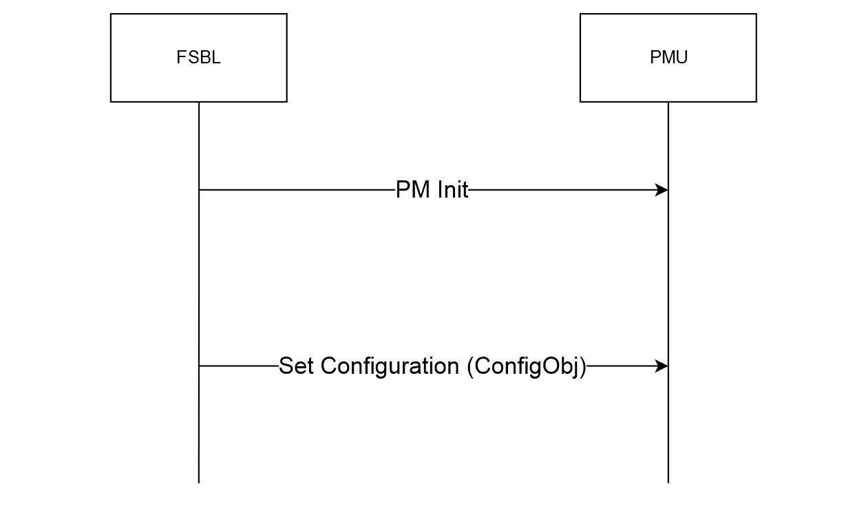
Initial Configuration at Boot
At boot-up:- FSBL sends the config object to PMU with the Set Configuration API
- PMU parses config object and configures
- PMU powers off all nodes which are unused after all the masters have finished initialization
Error Handling in PMU FW
Error Management Hardware
Zynq MPSoC has a dedicated error handler to aggregate all the fatal errors across the SoC and handle them. Refer to the TRM/Arch Spec for details.All fatal errors routed to Error Manager can either set to be handled by HW ( and trigger a SRST/PoR/PS Error Out) or trigger an interrupt to PMU.
Error Management in PMU Firmware
Important Note: To enable Error Management module in PMUFW, the macro ENABLE_EM needs to be defined either in the compiler flags or in file xpfw_config.cPMU Firmware provides APIs to register custom error handlers or assign a default SRST/PoR/PS Error Out action in response to an Error. There is a specific module (xpfw_mod_em.c) already provided in PMUFW and it is enabled by default.
All error handling code should reside in this module and there are already a couple of examples on handling WDT errors.
Action for each error can be setup using XPfw_EmSetAction API:
/**
 * Set action to be taken when specific error occurs
 *
 * @param ErrorId is the ID for error as defined in this file
 * @param ActionId is one of the actions defined in this file
 * @param ErrorHandler is the handler to be called in case custom action
 *
 * @return XST_SUCCESS if the action was successfully registerd
 *         XST_FAILURE if the registration fails
 */
s32 XPfw_EmSetAction(u8 ErrorId, u8 ActionId, XPfw_ErrorHandler_t ErrorHandler);
| Action ID | Description |
| EM_ACTION_POR | Trigger a Power-On-Reset |
| EM_ACTION_SRST | Trigger a System Reset |
| EM_ACTION_CUSTOM | Call the custom handler registered as ErrorHandler param |
| EM_ACTION_PSERR | Trigger a PS-Error out action |
List of Error IDs for ErrorId parameter:
| Error ID | Description |
| EM_ERR_ID_CSU_ROM | Errors logged by CSU Boot ROM (CBR) |
| EM_ERR_ID_PMU_PB | Errors logged by PMU Boot ROM (PBR) in the pre-boot stage |
| EM_ERR_ID_PMU_SERVICE | Errors logged by PBR in service mode |
| EM_ERR_ID_PMU_FW | Errors logged by PMUFW |
| EM_ERR_ID_PMU_UC | Un-Correctable Errors logged by PMU HW. This includes PMU ROM validation Error, PMU TMR Error, uncorrectable PMU RAM ECC Error, and PMU Local Register Address Error. |
| EM_ERR_ID_CSU | CSU HW related Errors |
| EM_ERR_ID_PLL_LOCK | Errors set when a PLL looses lock (These need to be enabled only after the PLL locks-up) |
| EM_ERR_ID_PL | PL Generic Errors passed to PS |
| EM_ERR_ID_TO | All Time-out Errors [FPS_TO, LPS_TO] |
| EM_ERR_ID_AUX3 | Auxilliary Error 3 |
| EM_ERR_ID_AUX2 | Auxilliary Error 2 |
| EM_ERR_ID_AUX1 | Auxilliary Error 1 |
| EM_ERR_ID_AUX0 | Auxilliary Error 0 |
| EM_ERR_ID_DFT | Error associated with the unexpected enablement of DFT features |
| EM_ERR_ID_CLK_MON | Clock Monitor Error |
| EM_ERR_ID_XMPU | XPMU Errors [LPS XMPU, FPS XPMU] |
| EM_ERR_ID_PWR_SUPPLY | Supply Detection Failure Errors |
| EM_ERR_ID_FPD_SWDT | FPD System Watch-Dog Timer Error |
| EM_ERR_ID_LPD_SWDT | LPD System Watch-Dog Timer Error |
| EM_ERR_ID_RPU_CCF | Asserted if any of the RPU CCF errors are generated |
| EM_ERR_ID_RPU_LS | Asserted if any of the RPU CCF errors are generated |
| EM_ERR_ID_FPD_TEMP | FPD Over Temperature Alert |
| EM_ERR_ID_LPD_TEMP | LPD Over Temperature Alert |
| EM_ERR_ID_RPU1 | RPU1 Error including both Correctable and Uncorrectable Errors |
| EM_ERR_ID_RPU0 | RPU0 Error including both Correctable and Uncorrectable Errors |
| EM_ERR_ID_OCM_ECC | OCM Uncorrectable ECC Error |
| EM_ERR_ID_DDR_ECC | DDR Uncorrectable ECC Error |
Example for Error Management (Custom Handler)
For this example OCM uncorrectable error (EM_ERR_ID_OCM_ECC) is considered. A custom handler is registered for this error in PMUFW and the handler in this case just prints out the error message. In a more realistic case, the corrupted memory may be reloaded, but this example is just limited to clearing the error and printing a message.Adding Error Handler in PMUFW:
Add the OCM error handler to the xpfw_mod_em.c file as below:

/* OCM Uncorrectable Error Handler */
static void OcmErrHandler(u8 ErrorId)
{
	XPfw_Printf(DEBUG_DETAILED, "EM: OCM ECC error detected\n");
	/* Clear the Error Status in OCM registers */
	XPfw_Write32(0xFF960004, BBIT(7));
}

And the OCM ECC error action is set to PS Error out by default. To change this, make the following change for EM_ERR_ID_OCM_ECC entry in ErrorTable structure in xpfw_error_manager.c file

Original:
[EM_ERR_ID_OCM_ECC] = { .Type = EM_ERR_TYPE_1, .RegMask = PMU_GLOBAL_ERROR_STATUS_1_OCM_ECC_MASK, .Action = EM_ACTION_PSERR, .Handler = NullHandler},

Modify the code to change the error action to "Interrupt to PMU":
[EM_ERR_ID_OCM_ECC] = { .Type = EM_ERR_TYPE_1, .RegMask = PMU_GLOBAL_ERROR_STATUS_1_OCM_ECC_MASK, .Action = EM_ACTION_CUSTOM, .Handler = OcmErrHandler},
;# Enable ECC UE interrupt in OCM_IEN
mwr -force 0xFF96000C [expr 1<<7]

;# Write to Fault Injection Data 0 Register OCM_FI_D0
;# Errors will be injected in the bits which are set, here its bit0, bit1
mwr -force 0xFF96004C 3

;# Enable ECC and Fault Injection
mwr -force 0xFF960014 1
;
# Clear the Count Register : OCM_FI_CNTR
mwr -force 0xFF960074 0
;# Now write data to OCM for the fault to be injected
# Since OCM does a RMW for 32-bit transactions, it should trigger error here
mwr -force 0xFFFE0000 0x1234

;# Read back to trigger error again
mrd -force 0xFFFE0000
The above code is in TCL for debugger. Same can be easily ported to a 'C' source by just replacing the mwr/mrd with Xil_Out32/Xil_In32
Example for Error Management ( PoR as a response to Error)
Some error may be too fatal and the system recovery from those errors may not be feasible without doing a Reset of entire system. In such cases PoR or SRST can be used as actions. In this example we use PoR reset as a response to the OCM ECC double-bit error.Here is the code that adds the PoR as action:
To change OCM ECC error action to PoR, make the following change for EM_ERR_ID_OCM_ECC entry in ErrorTable structure in xpfw_error_manager.c file

Original:
[EM_ERR_ID_OCM_ECC] = { .Type = EM_ERR_TYPE_1, .RegMask = PMU_GLOBAL_ERROR_STATUS_1_OCM_ECC_MASK, .Action = EM_ACTION_PSERR, .Handler = NullHandler},

Modify the code to change the error action to "Power on Reset":
[EM_ERR_ID_OCM_ECC] = { .Type = EM_ERR_TYPE_1, .RegMask = PMU_GLOBAL_ERROR_STATUS_1_OCM_ECC_MASK, .Action = EM_ACTION_POR, .Handler = NullHandler},
PMU RAM also gets cleared off during a PoR, so PMUFW needs to be reloaded.
Example for changing error action for FPD/LPD WDT
Changing error action for FPD WDT:
If FSBL is running on A53, FPD WDT error action is set to SWDT_EM_ACTION based on https://github.com/Xilinx/embeddedsw/blob/master/lib/sw_apps/zynqmp_pmufw/src/xpfw_config.h#L325
Otherwise, it is set to SRST

To change error action of FPD WDT to POR if FSBL is running on A53
Original at https://github.com/Xilinx/embeddedsw/blob/master/lib/sw_apps/zynqmp_pmufw/src/xpfw_mod_common.c#L70:
			(void)XPfw_EmSetAction(EM_ERR_ID_FPD_SWDT, SWDT_EM_ACTION,
						ErrorTable[EM_ERR_ID_FPD_SWDT].Handler);

Modified:
			(void)XPfw_EmSetAction(EM_ERR_ID_FPD_SWDT, EM_ACTION_POR,
						ErrorTable[EM_ERR_ID_FPD_SWDT].Handler);

To change error action of FPD WDT to POR if FSBL is running on R5
Original at https://github.com/Xilinx/embeddedsw/blob/master/lib/sw_apps/zynqmp_pmufw/src/xpfw_mod_common.c#L77:
			(void)XPfw_EmSetAction(EM_ERR_ID_FPD_SWDT, EM_ACTION_SRST,
						ErrorTable[EM_ERR_ID_FPD_SWDT].Handler);

Modified:
			(void)XPfw_EmSetAction(EM_ERR_ID_FPD_SWDT, EM_ACTION_POR,
						ErrorTable[EM_ERR_ID_FPD_SWDT].Handler);
Changing error action for LPD WDT:
If FSBL is running on R5, LPD WDT error action is set to SWDT_EM_ACTION based on https://github.com/Xilinx/embeddedsw/blob/master/lib/sw_apps/zynqmp_pmufw/src/xpfw_config.h#L325
Otherwise, it is set to SRST

To change error action of LPD WDT to POR if FSBL is running on R5
Original at https://github.com/Xilinx/embeddedsw/blob/master/lib/sw_apps/zynqmp_pmufw/src/xpfw_mod_common.c#L80:
			(void)XPfw_EmSetAction(EM_ERR_ID_LPD_SWDT, SWDT_EM_ACTION,
							ErrorTable[EM_ERR_ID_LPD_SWDT].Handler);

Modified:
			(void)XPfw_EmSetAction(EM_ERR_ID_LPD_SWDT, EM_ACTION_POR,
							ErrorTable[EM_ERR_ID_LPD_SWDT].Handler);

To change error action of LPD WDT to POR if FSBL is running on A53
Original at https://github.com/Xilinx/embeddedsw/blob/master/lib/sw_apps/zynqmp_pmufw/src/xpfw_mod_common.c#L73:
			(void)XPfw_EmSetAction(EM_ERR_ID_LPD_SWDT, EM_ACTION_SRST,
							ErrorTable[EM_ERR_ID_LPD_SWDT].Handler);

Modified:
			(void)XPfw_EmSetAction(EM_ERR_ID_LPD_SWDT, EM_ACTION_POR,
							ErrorTable[EM_ERR_ID_LPD_SWDT].Handler);
Adding a Custom Module
Creating a New Module
Each set of user defined routines performing a specific functionality should be designed to be a module in PMUFW. These files should be self contained and can use APIs from xpfw_core.h to call in FW routines. Each module should support the following interfaces:1. Config Handler : Called during Init.
2. Event Handler: When a registered event is triggered
3. IPI Handler: When an IPI Message arrives with the registered IPI ID
To create a module, in the user_startup routine:
PmModPtr = XPfw_CoreCreateMod();
(void)XPfw_CoreSetCfgHandler(PmModPtr, PmCfgInit);
(void)XPfw_CoreSetEventHandler(PmModPtr, PmEventHandler);
(void)XPfw_CoreSetIpiHandler(PmModPtr, PmIpiHandler,0U)
Adding a Task to Scheduler
Tasks are functions which take void args and return void. Currently PMU Firmware has no way to check that the task returns in a pre-determined time, so this needs to be ensured by the task design. Let us consider a task which prints out a message:void TaskPrintMsg(void)
{
xil_printf("Task has been triggered\r\n");
}
Status = XPfw_CoreScheduleTask(TaskModPtr, 500U, TaskPrintMsg);
if(XST_SUCCESS == Status) {
    xil_printf("Task has been added successfully !\r\n");
}
else {
    xil_printf(Ërror: Failed to add Task.!\r\n");
}
Registering for an Event
All interrupts that come into PMU are exposed to user as Events with specific EVENTIDs defined in xpfwevents.h; Any module can register for an event (usually in CfgInitHandler) and the module's EventHandler will be called when an event is triggered. To register for an RTC Event:Status = XPfw_CoreRegisterEvent(ModPtr,XPFW_EV_RTC_SECONDS);
Example of an EventHandler
void RtcEventHandler(const XPfw_Module_t *ModPtr, u32 EventId)
{
    xil_printf("MOD%d:EVENTID: %d\r\n", ModPtr->ModId, EventId);
    if(XPFW_EV_RTC_SECONDS == EventId){
            /* Ack the Int in RTC Module */
            Xil_Out32(RTC_RTC_INT_STATUS,1U);
            xil_printf("RTC: %d \r\n", Xil_In32(RTC_CURRENT_TIME));
    }
}
PMU Firmware Memory Footprint
This section contains the approximate details of PMU Firmware Memory Footprint with various modules enabled.In PMU Firmware,
- PM and FPGA modules are enabled by default. FPGA block in PMU Firmware does the xilfpga and xilsecure functionality which performs loading of bitstream to PL, loading of secure image to memory and reading FPGA status. FPGA block does not have a separate build flag for itself and is part of PM module.
- Error Management and Restart modules are not enabled by default
Note: All of the metrics are with compilation optimized for size -Os. This optimization setting is enabled by default in Vitis. To disable the same, user need to follow the steps mentioned in Debugging PMU FW using Vitis section above
| S.No | Feature/Component | Size occupied (KB) | Free space (KB) | Additional Notes | Remarks |
| 1 | PMU Firmware without detailed debug prints enabled | 112.5 | 15.5 | This is with base PMU Firmware, PM module and FPGA block | |
| 2 | PMU Firmware with detailed debug prints enabled | 123 | 5 | Detailed debug prints are enabled when XPFW_DEBUG_DETAILED and DEBUG_MODE flags are defined | This estimation is with combination of (1) and (2) |
| 3 | PMU Firmware with Error Management Module enabled | 115.4 | 12.6 | Error Management module is enabled when ENABLE_EM and ENABLE_SCHEDULER flags are defined | This estimation is with combination of (1) and (3) |
| 4 | PMU Firmware with Restart Module enabled | 117.5 | 10.5 | Restart module is enabled when ENABLE_RECOVERY, ENABLE_ESCALATION and CHECK_HEALTHY_BOOT flags are defined along with ENABLE_EM and ENABLE_SCHEDULER flags | This estimation is with combination of (1) and (4) |
Examples to enable/disable modules
- PM module is enabled by default with ENABLE_PM build flag. This build flag is defined in <PMU Firmware Application>/src/xpfw_config.h file. To disable PM Module, user need to make changes to xpfw_config.h file by removing/commenting defined ENABLE_PM flag.
- All other build flags can be enabled by following the below steps.
- Right click on the PMU Firmware project and select "C/C++ Build Settings" option. Properties window appears
- Select "Settings" from "C/C++ Build" options. In "Tool Settings" tab, select "Symbols" from "Microblaze gcc compiler" option
- Click on "Add" under "Defined symbols (-D)"
- Enter flag name to define and click "Ok"
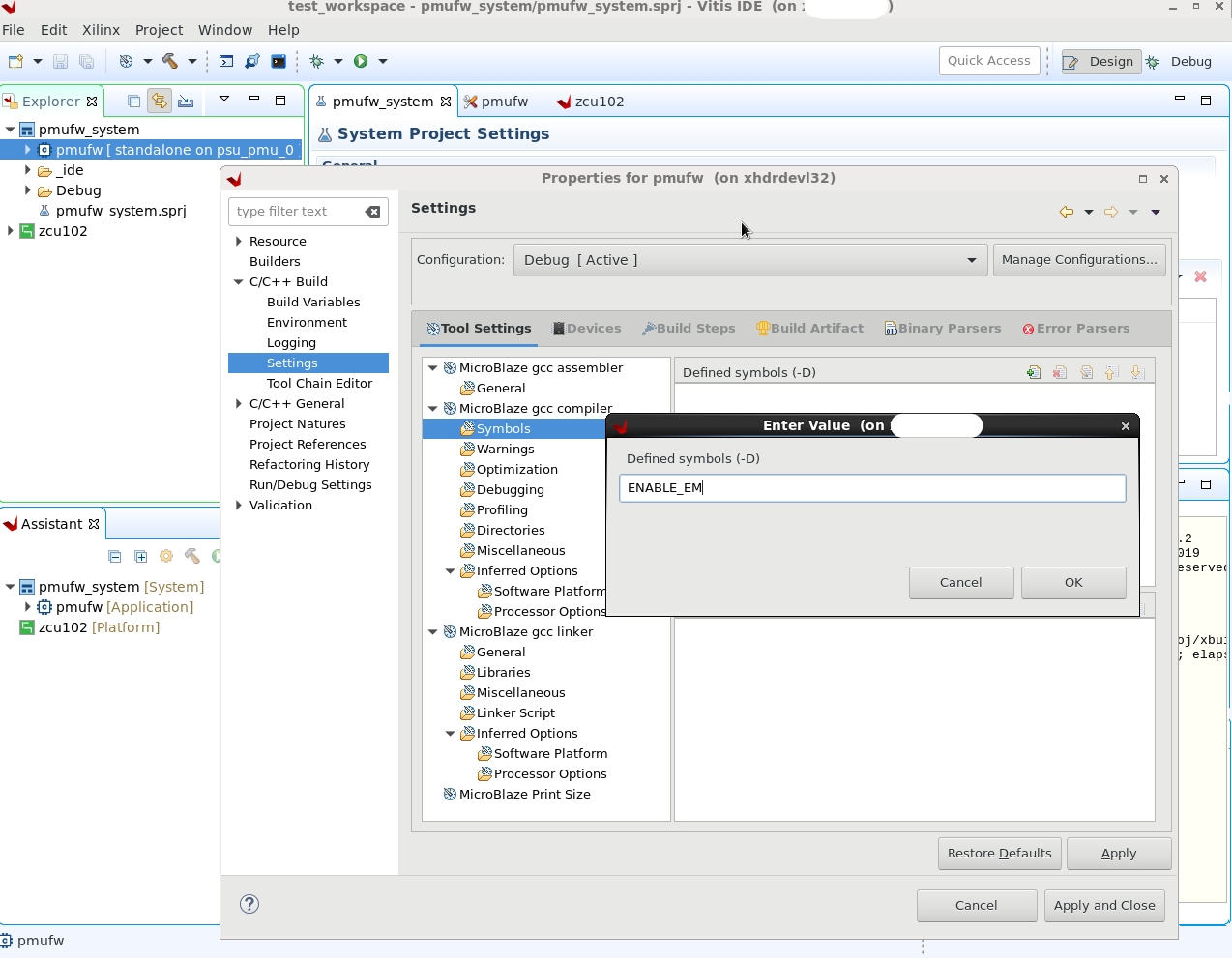
- Again click "Ok" on properties window and the application will start building with the new compile flags defined
Registers reserved for PMU Firmware
Following are the general storage registers used by PMU Firmware- 0xFFD80034 (PMU_GLOBAL_GLOBAL_GEN_STORAGE2) → Since 2018.1 if POS is enabled, FSBL waits till PMU has finished resuming by polling this register. Users are free to use this register after reset so it can still be considered as "reserved for customers".
- 0xFFD80038 (PMU_GLOBAL_GLOBAL_GEN_STORAGE3) → Since 2018.1 if POS is enabled, PMU waits till FSBL has finished reading the boot type. This additional handshake step is required in boot scenarios where FSBL is started by CSU. PFW must wait for CSU to trigger FSBL start otherwise there may be race condition where PFW is trying to restore state of processor as part of resume from Power Off Suspend sequence while CSU is trying to run FSBL on that same processor. Users are free to use this register after reset so it can still be considered as "reserved for customers".
- 0xFFD80040 (PMU_GLOBAL_GLOBAL_GEN_STORAGE4 - bit 0) → This register bit needs to be written by upper layer APU applications. So that, in case of FPD WDT error (and when ENABLE_RECOVERY and CHECK_HEALTHY_BOOT macros are defined), PMU checks this register to find out if previous boot was successful and does subsystem restart only if last boot was successful.
- 0xFFD80040 (PMU_GLOBAL_GLOBAL_GEN_STORAGE4 - bits 1 and 2) → Since 2018.3, these bits are used to know the status of RPU 0 and RPU 1 usage which will be updated by FSBL. Based on this information, PMU will decide whether to shutdown the unused RPU cores or not.
- 0xFFD80040 (PMU_GLOBAL_GLOBAL_GEN_STORAGE4 - bits 3 and 4) → Since 2018.3, these bits are used to set the restart scope to ATF in case of WDT restart.
- 0XFFD80040 (PMU_GLOBAL_GLOBAL_GEN_STORAGE4 - bit 16) → Written by PMU Firmware, FSBL uses this register bit to know if reset is APU only reset.
- 0XFFD80044 (PMU_GLOBAL_GLOBAL_GEN_STORAGE5 - bit 0) → Written by FSBL, PMU Firmware uses this register to know if FSBL has completed its execution. Since 2018.1, this check is performed to initialize and start the CSU WDT timer when ENABLE_WDT macro is defined.
- 0XFFD80044 (PMU_GLOBAL_GLOBAL_GEN_STORAGE5 - bits 1 and 2) → Written by FSBL. PMU Firmware uses these bits to know if FSBL is running on which processor. 01: APU, 10: RPU0, 11: RPU LS
- 0xFFD80044 (PMU_GLOBAL_GLOBAL_GEN_STORAGE5 - bits 16 to 23) → Since 2018.3, XilFPGA library in PMU uses these bits to store the PL state to know whether secure bit-stream or non-secure bit-stream or no bit-stream loaded. This information is used by XilFPGA Readback feature to dis-allow readback in case secure bit-stream is loaded.
- 0xFFD80050 (PMU_GLOBAL_PERS_GLOBAL_GEN_STORAGE0) → This register is used to store Exception Status Register (ESR) value of the PMU Microblaze register when any exception occurs.
- 0xFFD80054 (PMU_GLOBAL_PERS_GLOBAL_GEN_STORAGE1) → This register is used to store Exception Address Register (EAR) value of the PMU Microblaze register when any exception occurs.
- 0xFFD8006C (PMU_GLOBAL_PERS_GLOBAL_GEN_STORAGE7 - bit 3) → Since 2018.3, PMU is using this bit to indicate FSBL whether DDR is in self-refresh mode or not. PMU will set this bit if DDR is in self-refresh during warm-restart and clears after the restart.
And 0xFFD8004C (PMU_GLOBAL_GLOBAL_GEN_STORAGE7) is used by PMU_ROM. This register is used in case we encounter problems with the PL Power Up routine in which ROM does not wait long enough for the PL to come out of reset. The time ROM waits can be extended by increasing the value of this register.
Revision History
What's new in 2022.1 release
- Updated to give/change permissions for writing another overlay config object
- Cleanup of dynamic feature config logic to enable them only if dynamic feature config is enabled
- Added IOCTL support for dynamic SD, GEM and USB configuration under ENABLE_DYNAMIC_MIO_CONFIG macro which is disabled by default
Give an error when same overlay configuration for existing node is called multiple times
Added provision in ZynqMP PMUFW to skip XFPGA_SECURE_MODE macro
- Return unique error code if slave is already configured
- Added support for feature check API
- Implemented new API's to get XilFPGA component information
- Re-apply PLL workaround when DP device is added
Provide user option to manually enable DDR XMPU settings using ENABLE_DDR_XMPU macro which is disabled by default
- Fix issue on SOM related to enabling build flags
- There is a known GCC warning observed while building PMUFW:
In function 'PmSecureAes': ../src/pm_core.c:1079:34: warning: 'InstancePtr' may be used uninitialized
What's new in 2021.2 release
Following are the new features added in PMU Firmware in 2021.2 release:
- Add support for dynamic loading of config object
- Add IOCTL call support in PMUFW
- Add support for runtime feature configuration for OT
- Add runtime support for External WDT
- Add min and max limit checks for OT and External WDT features
- Do not turn off FPD when USB wakeup source is enabled as USB controller uses GT from FPD
- Handle APU restart gracefully if copying FSBL to DDR is failed
What's new in 2021.1 release
Following are the new features added in PMU Firmware in 2021.1 release:
- Add DDR related code under DDR define macro
- Minor updates to FPGA load API
- Check master permission for system shutdown and system restart
- Remove CRC16 logic from PMU Firmware and move it to IPI driver
- Give provision to enable or disable PMU build flags using config.h or compiler build flags
- Add PMU Local SERV_ERR register to MMIO register list
- Move call of PmProbeRpuState from PmGetNodeStatus to PmRequestWakeup
- Change scope for PmKillBoardPower to use in multiple modules
- Provide an option to direct board power down (ultra96)
- Add external WDT module
- Add Over Temperature Shutdown module
- Fix voltage status param reading
- Assign PL to PMU only during subsystem restart
- Added support for programming PUF Fuses as general purpose data
What's new in 2020.1 release
Following are the new features added in PMU Firmware in 2019.1 release:
- Implement idle hook for node NAND to be called before applying soft reset to NAND
- Keep PL power ON during APU/RPU subsystem restart
- Add support for idling GPU and GPU_PP nodes
- Implement HW exception handler for PMU
- Enable SLVERR for peripherals used by PMU
- Provide build option to disable FSBL copy to DDR feature
- Skip copying FSBL to DDR if FSBL image is encrypted
- Add new module to monitor RPU run mode
What's new in 2019.2 release
Following are the new features added in PMU Firmware in 2019.2 release:
- Change power state of power domain or island only if it is powered up by checking PWR_STATUS register
- Change WDT timeout when performing secure operations which take more time
- Added power down permission check for processor and PLL nodes in PmForcePowerDown()
- Added support for RPU only subsystem restart case
What's new in 2019.1 release
Following are the new features added in PMU Firmware in 2019.1 release:
- Idle nodes only once even if they are assigned to multiple masters
- Add support to idle and reset all twelve TTCs
- Support for APU only reset even if secure bitstream loading via OCM feature is executed
- Updates to XilFPGA APIs to support latest 5.0 version
- Add checksum support for IPI messages
- Add permission check for modifying error actions over IPI
- Bypass DDR related code if DDR is not present in the design
- Register handler and trigger FW error when Assert occurs
- Add hook for custom module in PMU Firmware
- Add handler for EMIO get reset status
- Add PMU RAM ECC error injection STL during PMU startup
- Add check for number of users for vpll
- Add support for Ultra96 power button
What's new in 2018.3 release
- PMU Firmware support for PL Configuration Readback
- PMU Firmware support for AES encryption and decryption
- Put DDR in self refresh before warm-restart
- Implementation of clock EEMI APIs
- Addition of CSU/PMU global register access via MMIO calls
- Support to set restart scope during WDT restart
- PMU Firmware support for eFUSE access
- Implementation of pin mux functionality in PMU Firmware
What's new in 2018.2 release
- Provide read/write access to AFI configuration registers through MMIO call
- While configuring PLL lock errors and its actions in EM module, wait for FSBL to complete psu_init to avoid initial PLL lock errors that occurs during FSBL initialization
What's new in 2018.1 release
Following are the new features added in PMU Firmware in 2018.1 release:- PMU fail safe mechanism with CSU WDT is added
- Implemented idle hooks for nodes USB, DP and SATA
- Added suppoort for graceful force powerdown of PU
- This is to prevent any mid-flight AXI transactions from locking up the interconnect and hanging the device
- Added wake on USB support to wakeup all masters for which USB is set as wakeup source
- Added GPO section to config object to get the initial state of PMU GPO's and configure them in PMU Firmware
- Added modularity of xilfpga and xilsecure features using compiler switches
- Added Power Off Suspend to RAM feature
- Added support for resetting GPIO5 resets going to PL
- Added API to support secure single partition image
What's new in 2017.4 release
Following are the new features added in PMU Firmware in 2017.4 release:- Exported efuse IP disable as part of version string in PmGetChipid to recognize eg/cg/ev devices
What's new in 2017.3 release
Following are the new features added in PMU Firmware in 2017.3 release:- Added three level debug prints support in PMU Firmware application
- Added support to PMU EM module to set/remove the error action for any error at run time using IPI
- Added support to log EM errors that come to PMU and send when the target requests over IPI
- Added SRST support for FPD WDT
- Added xilsecure API calls to support xilsecure functionality from Linux
Related Links
Related content
© Copyright 2019 - 2022 Xilinx Inc. Privacy Policy