/
Zynq UltraScale+ MPSoC Non-Secure Boot
Zynq UltraScale+ MPSoC Non-Secure Boot
Table of Contents
1.0 Zynq UltraScale+ MPSoC boot in Non Secure Boot
This page provides the instructions to create images and boot the Zynq UltraScale+ MPSoc in Non-Secure method.
This page addresses the procedures based on the following
1. ZCU102 hardware platform
2. QEMU simulation platform
1.1 ZCU102 Hardware platform
This section provides the image creation and flashing procedures in Non Secure mode for ZCU102 hardware platform1. Generation of images using PetaLinux environment.
2. Programming QSPI flash from U-Boot and verify the QSPI boot.
3. Programming QSPI flash from Linux and verify the QSPI boot.
4. Programming the SD Card from Linux and verify the SD boot.
5. Booting Linux from U-Boot using TFTP.
1.1.1 Generate images using PetaLinux environment
Follow the steps below to create boot images using Petalinux on Host Linux PC
1. Set the Petalinux environment using the following command based on shell or cshell prompt
$ source <Petalinux installation path>/settings64.sh
$ source <Petalinux installation path>/settings64.csh
$ source <SDK installation path>/installs/lin64/SDK/<SDK release version>/settings64.sh
$ source <SDK installation path>/installs/lin64/SDK/<SDK release version>/settings64.csh
$ petalinux-create -t project -n <project-name> --template zynqMP
$ cd <project-name>
petalinux-config
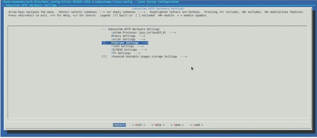
Figure 1: Configure the Ethernet settings as static
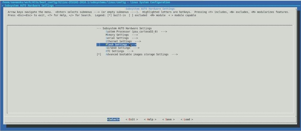
Figure 2: Configure the qspi partition information.
Figure 3: Set the QSPI partitions
Figure 4: Uncheck the tftp boot from Image package Configuration.
5. Modify the QSPI partitions information in device tree file system-conf.dtsi as follows
&&qspi {
    #address-cells = <1>;
    #size-cells = <0>;
    flash0: flash@0 {
        compatible = "micron,n25q128";
        reg = <0x0>;
        #address-cells = <1>;
        #size-cells = <1>;
        spi-max-frequency = <50000000>;
        partition@0x00000000 {
            label = "boot";
            reg = <0x00000000 0x100000>;
        };
                partition@0x01000000 {
            label = "bootenv";
            reg = <0x00100000 0x40000>;
        };
        partition@0x00140000 {
            label = "kernel";
            reg = <0x00140000 0x2000000>;
        };
        partition@0x01240000 {
            label = "device-tree";
            reg = <0x02140000 0x80000>;
        };
    };
};
5. Build the images using Petalinux utils as follows
$ petalinux-build -v(verbose)
Tested images are in file
1.1.2 Programming the QSPI flash from U-Boot and verify the QSPI boot.
1. Refer to the section Generate Boot Images using Petalinux
2. Create the boota53_sd.bif for making the SD images as follows
the_ROM_image:
{
 [fsbl_config] a53_x64
 [bootloader] zynqmp_fsbl.elf
 [destination_cpu=a53-0] bl31.elf
 [destination_cpu=a53-0] u-boot.elf
}
$ cd images/linux
$ bootgen -image boota53_sd.bif -arch zynqmp -w -o i boot.bin
the_ROM_image:
{
[fsbl_config] a53_x64
[bootloader] zynqmp_fsbl.elf
[destination_cpu=a53-0] hello_world_a53_0.elf
}
$ cd images/linux
$ bootgen -image boota53_qspi.bif -arch zynqmp -w -o i boot_qspi.bin
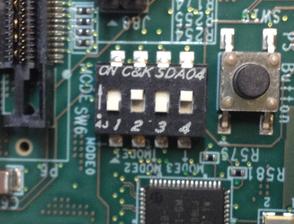
7. Connect the board as per the following figure with SW6 as follows for SD card
Figure 5: SD Boot mode Switch settings
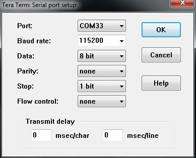
8. Connect the Serial Cable to the board and Open the serial terminal connected on COM interface0 with settings as below figure
Figure 6: Serial console settings
9. Power on the board, user can see the log on the serial terminal stops at u-boot prompt
10. Copy the boot_qspi.bin from SD card into QSPI using the following commands
ZynqMP>sf probe 0 0 0
ZynqMP>sf erase 0 0x100000
ZynqMP>fatload mmc 0 0x100000 boot_qspi.bin
ZynqMP>sf write 0x100000 0x0 0x100000
Figure 7: QSPI Boot mode switch settings
12. User should see the Hello World A53_0 message on the serial terminal.
1.1.3 Programming the QSPI flash from Linux and verify the QSPI boot.
1. Refer to the section Generate Boot Images using Petalinux.
2. Create the "boota53_sd.bif" with the following contents:
$cat boot_sd.bif
the_ROM_image:
{
  [fsbl_config] a53_x64
  [bootloader] zynqmp_fsbl.elf
  [destination_cpu=a53-0] bl31.elf
  [destination_cpu=a53-0] u-boot.elf
}
3. Create the boot.bin for SD Card using the following commands
$ cd images/linux
$ bootgen -image boota53_sd.bif -arch zynqmp -w -o i boot.bin
4. Copy the images(boot.bin, image.ub, Image and system.dtb) into SD card.
5. Insert the SD-MMC memory card on the ZCU102 board. Refer to Figure 5 For SD boot mode switch settings
6. Connect the Serial Cable to the board and Open the serial terminal connected on COM interface0. Refer to the Figure 6.
7. Power on the board. User can see the log on the serial terminal .
8. Once the Linux boots up , login ID prompts, provide login details as follows
ID : "root"
password : "root"
9. Mount the SD card using the following commands
root@Xilinx-ZCU102-<release>: mkdir /mnt/sd
root@Xilinx-ZCU102-<release>: mount /dev/mmcblk0<p1> /mnt/sd
root@Xilinx-ZCU102-<release>: cd /mnt/sd
10. Copy the images from SD card to QSPI MTD partition as per the MTD partitions on the board
$cat /proc/mtd
root@Xilinx-ZCU102-2016_1:/mnt/sd# cat /proc/mtd
dev:    size   erasesize  name
mtd0: 00100000 00002000 "boot"
mtd1: 00040000 00002000 "bootenv"
mtd2: 02000000 00002000 "kernel"
mtd3: 00020000 00002000 "devicetree"
mtd4: 00100000 00002000 "qspi-fsbl-uboot"
mtd5: 01e00000 00002000 "qspi-linux"
mtd6: 00020000 00002000 "qspi-device-tree"
root@Xilinx-ZCU102-<release>: flashcp -v boot.bin /dev/mtd0
root@Xilinx-ZCU102-<release>: flashcp -v Image /dev/mtd2
root@Xilinx-ZCU102-<release>: flashcp -v system.dtb /dev/mtd3
11. Restart the board by keeping the boot mode in QSPI. Refer to the Figure 7
12. Stop at u-boot prompt
13. Booting from QSPI, following commands should run manually on u-boot prompt.
14. Linux should boot from QSPI flash.
1.1.4 Programming the SD Card from Linux and verify the SD boot
1. Refer to the section Generate Boot Images using PetaLinux
2. Assuming that the QSPI is already flashed using the QSPI flashing from Linux Procedure. Refer to Figure 7 for QSPI boot mode.
3. Connect the Serial Cable to the board and Open the serial terminal connected on COM interface0 with settings. Refer to Figure 6.
4. Power on the board with QSPI mode. User can see the log on the serial terminal
5. Once the Linux boots up and login ID prompts, provide the login details as below.
ID : "root"
password :"root"
6. Mount the SD card using the following commands
root@Xilinx-ZCU102-<release>: mkdir /mnt/sd
root@Xilinx-ZCU102-<release>: mkdosfs /dev/mmcblk0
root@Xilinx-ZCU102-<release>: mount /dev/mmcblk0 /mnt/sd
root@Xilinx-ZCU102-<release>: cd /mnt/sd
7. Copy the image from QSPI MTD partition to SD Card. To know which corresponds to QSPI partition, use
$cat /proc/mtd
root@Xilinx-ZCU102-<release>:/mnt/sd# cat /proc/mtd
dev:    size   erasesize  name
mtd0: 00100000 00002000 "boot"
mtd1: 00040000 00002000 "bootenv"
mtd2: 02000000 00002000 "kernel"
mtd3: 00020000 00002000 "devicetree"
mtd4: 00100000 00002000 "qspi-fsbl-uboot"
mtd5: 01e00000 00002000 "qspi-linux"
mtd6: 00020000 00002000 "qspi-device-tree"
root@Xilinx-ZCU102-<release>: cp /dev/mtd<part> boot.bin
root@Xilinx-ZCU102-<release>: cp /dev/mtd<part> Image
root@Xilinx-ZCU102-<release>: cp /dev/mtd<part> system.dtb
8. Restart the board by keeping the boot mode in SD. Refer to Figure 5 for SD boot mode.
9. User should see the Linux booting on the serial terminal using SD card.
1.1.5 Booting Linux From U-Boot Using TFTP
Procedure to be followed on the Host PC
1. Download TFTP server application from Cnet .
2. Install the application
3. Set the current directory path to the folder in which images are generated.
4. Configure the client ip address in tftp server.
Procedure to be followed on ZCU102 Target board
1.Refer to the section Generate Boot Images using Petalinux
2.Create the "boota53_sd.bif" with the following contents:
$cat boota53_sd.bif
the_ROM_image:
{
  [fsbl_config] a53_x64
  [bootloader] zynqmp_fsbl.elf
  [destination_cpu=a53-0] bl31.elf
  [destination_cpu=a53-0] u-boot.elf
}
$ cd images/linux
$ bootgen -image boota53_sd.bif -arch zynqmp -w -o i boot.bin
5. Connect the board for SD boot mode. Refer to Figure 5.
6. Connect the board and the host PC with a Ethernet Cable.
7. Connect the Serial Cable to the board. Refer to Figure 6 for console settings
8. Power on the board. User can see the log on the serial terminal which stops at u-boot prompt
9. Set the environment to setup the server and client ip address on u-boot prompt
setenv serverip <ip-address>
setenv ipaddr <ip-address>
setenv tftpblocksize 512
11. Run a ping test to check if the connection is properly set.
ping <serverip>
If ping test works in U-boot, user should see the following log being displayed on the console
ZynqMP> ping 10.10.70.101
Gem.ff0e0000 Waiting for PHY auto negotiation to complete...... done
Using Gem.ff0e0000 device
host 10.10.70.101 is alive
12. Run the following commands to download the kernel and the device tree images.
tftpb 0x200000 Image
tftpb 0x7000000 system.dtb
13. Run the boot command
booti 0x200000 - 0x7000000
14.Kernel will boot and come to the linux prompt
1.2 QEMU Prodecures
The below section describes booting of QEMU in Non-Secure mode using the following boot devices:
- QSPI24
- NAND
- SD
1.2.1 QSPI24 Non-Secure Boot
1. Set the Petalinux environment using the following command
$source <Petalinux installation path>/settings.sh
2. Create a bif file “QSPI_R5_0.bif” with the following contents:
$cat QSPI_R5_0.bif
the_ROM_image:
{
[fsbl_config] r5_single
[bootloader] R5_FSBL.elf
[destination_cpu=r5-0] R5_core0_hello_world.elf
}
3. Run the bootgen tool to generate the bin file
$ bootgen -r -w –image ./QSPI_R5_0.bif -o Boot.bin
4. Create the QEMU QSPI single mode boot image
$ dd if=/dev/zero of=qemu_qspi_R5_0.bin bs=32M count=1
1+0 records in
1+0 records out
33554432 bytes (34 MB) copied, 0.300993 s, 111 MB/s
87448+0 records in
87448+0 records out
87448 bytes (87 kB) copied, 3.14043 s, 27.8 kB/s
5. Now the QEMU QSPI single mode boot image qemu_qspi_R5_0.bin can be used for the execution on QEMU
6. Execute the application on R5 core-0 using the following command
$ qemu-system-aarch64 -nographic -M arm-generic-fdt -dtb ./xilinx-zynqmp-arm.dtb -device loader,file=R5_FSBL.elf,cpu=4 -device loader,addr=0xff5e023c,
data=0x80008fde,data-len=4 -device loader,addr=0xff9a0000,data=0x80000218,data-len=4 -mtdblock qemu_qspi_R5.bin -boot mode=1
-------------------------------------------------------------------------------------------------------------------------------------------------------------
Xilinx Resticted QEMU Sep 29 2014 20:00:35.
This QEMU binary and its source are restricted to Xilinx internal
use only. Do not delete this message in source. Contact the Xilinx
QEMU Maintainer (git-dev@xilinx.com) for details on publishing QEMU
contributions to customers.
---------------------------------------------------------------------------------------------------------------------------------------------------------------
Xilinx First Stage Boot Loader
Release SW Beta1 Feb 5 2015-12:13:50
Platform: QEMU, RTL Version: 400
Cluster ID 0x80000004
Running on R5-0 Processor
Processor Initialization Done
In Stage 2
QSPI 24bit Boot Mode
QSPI is in single flash connection
Single Flash Information
FlashID=0x20 0xBB 0x19
MICRON 256M Bits
Multiboot Reg : 0x0
QSPI Reading Src 0x44, Dest FFFF6574, Length 4
.QSPI Reading Src 0x98, Dest FFFF6550, Length 4
.Image Header Table Offset 0x8C0
QSPI Reading Src 0x8C0, Dest FFFF1690, Length 40
.*Image Header Table Details*
Boot Gen Ver: 0x1020000
No of Partitions: 0x4
Partition Header Address: 0x260
Partition Present Device: 0x0
QSPI Reading Src 0x980, Dest FFFF16D0, Length 40
.QSPI Reading Src 0x9C0, Dest FFFF1710, Length 40
.QSPI Reading Src 0xA00, Dest FFFF1750, Length 40
.QSPI Reading Src 0xA40, Dest FFFF1790, Length 40
.Initialization Success
In Stage 3, Partition No:1
UnEncrypted data Length: 0x2
Data word offset: 0x2
Total Data word length: 0x2
Destination Load Address: 0x10223C
Execution Address: 0x100000
Data word offset: 0x4C9E
Partition Attributes: 0x508
QSPI Reading Src 0x13278, Dest 10223C, Length 8
.Partition 1 Load Success
In Stage 3, Partition No:2
UnEncrypted data Length: 0x25
Data word offset: 0x25
Total Data word length: 0x25
Destination Load Address: 0x0
Execution Address: 0x0
Data word offset: 0x4CA0
Partition Attributes: 0x508
Address 0xFFE00000, Length 10000, ECC initialized
QSPI Reading Src 0x13280, Dest FFE00000, Length 94
.Partition 2 Load Success
In Stage 3, Partition No:3
UnEncrypted data Length: 0x894
Data word offset: 0x894
Total Data word length: 0x894
Destination Load Address: 0x100000
Execution Address: 0x0
Data word offset: 0x4CD0
Partition Attributes: 0x508
QSPI Reading Src 0x13340, Dest 100000, Length 2250
...Partition 3 Load Success
All Partitions Loaded
In Stage 4
Running Cpu Handoff address: 0x100000, Exec State: 8
Exit from FSBL
Hello World
1.2.2 NAND Non-Secure Boot
1. Set the Petalinux environment using the following command
$source <Petalinux installation path>/settings.sh
2. Create a bif file “NAND.bif” with the following contents:
$cat NAND.bif
the_ROM_image:
{
[fsbl_config] a5x_x64
[bootloader] ron_a53_fsbl.elf
[destination_cpu=a5x-0] hello_world.elf
}
$ bootgen -r -w –image ./NAND.bif -o Boot.bin
4. Create the NAND boot image
$ dd if=/dev/zero of=nand.bin bs=1G count=4
4+0 records in
4+0 records out
4294967296 bytes (4.3 GB) copied, 50.9095 s, 84.4 MB/s
170980+0 records in
170980+0 records out
170980 bytes (171 kB) copied, 0.168898 s, 1.0 MB/s
$ qemu-nand-creator 16384 < nand.bin > qemu_nand.bin
(87 kB) copied, 3.14043 s, 27.8 kB/s
7. Execute the application on A53 core-0 using the following command
$ qemu-system-aarch64 -nographic -M arm-generic-fdt -hw-dtb xilinx-zynqmp-arm.dtb -device loader,file=./fsbl_a530.elf,cpu=0 -device loader,addr=0xfd1a0104,
data=0x8000000e,data-len=4 -pflash qemu_nand.bin -boot mode=4
-------------------------------------------------------------------------------------------------------------------------------------------------------------------
Xilinx Restricted QEMU Feb 13 2015 16:19:45.
This QEMU binary and its source are restricted to Xilinx internal
use only. Do not delete this message in source. Contact the Xilinx
QEMU Maintainer (qemu-dev@xilinx.com) for details on publishing QEMU
contributions to customers.
-------------------------------------------------------------------------------------------------------------------------------------------------------------------
WARNING: Image format was not specified for 'qemu_nand.bin' and probing guessed raw.
Automatically detecting the format is dangerous for raw images, write operations on block 0 will be restricted.
Specify the 'raw' format explicitly to remove the restrictions.
DDR test pass
Xilinx First Stage Boot Loader
Release SW Beta1 Feb 11 2015-18:14:27
Platform: QEMU, RTL Version: 400
Cluster ID 0x80000000
Running on A53-0 Processor
Processor Initialization Done
In Stage 2
NAND Boot Mode
Manufacturer: MICRON MT29F32G08ABCDBJ4 ,
Device Model: MT29F32G08ABCDBJ4 ,
Jedec ID: 0x2C
Bytes Per Page: 0x4000
Spare Bytes Per Page: 0x4C0
Pages Per Block: 0x100
Blocks Per LUN: 0x418
Number of LUNs: 0x1
Number of bits per cell: 0x1
Number of ECC bits: 0x1
Block Size: 0x400000
Number of Target Blocks: 0x418
Number of Target Pages: 0x41800
Nand Init Success
Multiboot Reg : 0x0
Image Header Table Offset 0x8C0
*Image Header Table Details*
Boot Gen Ver: 0x1020000
No of Partitions: 0x5
Partition Header Address: 0x260
Partition Present Device: 0x0
Initialization Success
In Stage 3, Partition No:1
UnEncrypted data Length: 0x6C8
Data word offset: 0x6C8
Total Data word length: 0x6C8
Destination Load Address: 0x0
Execution Address: 0x0
Data word offset: 0x7ED2
Partition Attributes: 0x100
Partition 1 Load Success
In Stage 3, Partition No:2
UnEncrypted data Length: 0x23A
Data word offset: 0x23A
Total Data word length: 0x23A
Destination Load Address: 0x1B40
Execution Address: 0x0
Data word offset: 0x85A0
Partition Attributes: 0x100
Partition 2 Load Success
In Stage 3, Partition No:3
UnEncrypted data Length: 0x1F02
Data word offset: 0x1F02
Total Data word length: 0x1F02
Destination Load Address: 0x2440
Execution Address: 0x0
Data word offset: 0x87E0
Partition Attributes: 0x100
Partition 3 Load Success
In Stage 3, Partition No:4
UnEncrypted data Length: 0x9
Data word offset: 0x9
Total Data word length: 0x9
Destination Load Address: 0x1AB4
Execution Address: 0x0
Data word offset: 0xA6F0
Partition Attributes: 0x100
Partition 4 Load Success
All Partitions Loaded
In Stage 4
Running Cpu Handoff address: 0x0, Exec State: 0
Exit from FSBL
Hello World
1.2.3 SD Non-Secure Boot
1. Set the Petalinux environment using the following command$source <Petalinux installation path>/settings.sh
2. Create a bif file “SD.bif” with the following contents:
$ cat SD.bif
the_ROM_image:}}
{
[fsbl_config] a5x_x64
[bootloader] ron_a53_fsbl.elf
[destination_cpu=a5x-0] A53_core0_hello_world.elf
}
$ bootgen -r -w -image SD.bif -o Boot.bin
4. Create the QEMU SD boot image
$ dd if=/dev/zero of=qemu_sd.img bs=128M count=1
1+0 records in
1+0 records out
134217728 bytes (134 MB) copied, 1.23445 s, 109 MB/s
mkfs.fat 3.0.26 (2014-03-07
5. Now the QEMU SD mode boot image qemu_sd.img can be used for the execution on QEMU
6. Execute the application on R5 core-0 using the following command
$ qemu-system-aarch64 -nographic -M arm-generic-fdt -dtb ./
xilinx-zynqmp-arm.dtb
-device loader,file=ron_a53_fsbl.elf,cpu=0 -device loader,addr=0xfd1a0104,
data=0x8000000e,data-len=4 -sd qemu_sd.img -boot mode=5
----
Xilinx Resticted QEMU Sep 29 2014 20:00:35.
This QEMU binary and its source are restricted to Xilinx internal
use only. Do not delete this message in source. Contact the Xilinx
QEMU Maintainer (git-dev@xilinx.com) for details on publishing QEMU
contributions to customers.
----
Xilinx First Stage Boot Loader
Release SW Beta1 Jan 29 2015-14:44:00
Platform: QEMU, RTL Version: 400
Cluster ID 0x80000000
Running on A53-0 Processor
Processor Initialization Done
In Stage 2
SD Boot Mode
SD: rc= 0
File name is BOOT.BIN
Multiboot Reg : 0x0
Image Header Table Offset 0x8C0
*Image Header Table Details*
Boot Gen Ver: 0x1020000
No of Partitions: 0x5
Partition Header Address: 0x260
Partition Present Device: 0x0
Initialization Success
In Stage 3, Partition No:1
UnEncrypted data Length: 0x6CE
Data word offset: 0x6CE
Total Data word length: 0x6CE
Destination Load Address: 0x0
Execution Address: 0x0
Data word offset: 0x7ED2
Partition Attributes: 0x100
Partition 1 Load Success
In Stage 3, Partition No:2
UnEncrypted data Length: 0x23A
Data word offset: 0x23A
Total Data word length: 0x23A
Destination Load Address: 0x1B40
Execution Address: 0x0
Data word offset: 0x85A0
Partition Attributes: 0x100
Partition 2 Load Success
In Stage 3, Partition No:3
UnEncrypted data Length: 0x1F02
Data word offset: 0x1F02
Total Data word length: 0x1F02
Destination Load Address: 0x2440
Execution Address: 0x0
Data word offset: 0x87E0
Partition Attributes: 0x100
Partition 3 Load Success
In Stage 3, Partition No:4
UnEncrypted data Length: 0x9
Data word offset: 0x9
Total Data word length: 0x9
Destination Load Address: 0x1AB4
Execution Address: 0x0
Data word offset: 0xA6F0
Partition Attributes: 0x100
Partition 4 Load Success
All Partitions Loaded
In Stage 4
Running Cpu Handoff address: 0x0, Exec State: 0
Exit from FSBL
Hello World running on A53 core 0
Related Links
Zynq UltraScale+ MPSoC Secure BootZynq Ultrascale+ MPSoC Multiboot and Fallback
Related content
Zynq Ultrascale+ MPSoC Security Features
Zynq Ultrascale+ MPSoC Security Features
More like this
Zynq UltraScale+ FSBL
Zynq UltraScale+ FSBL
Read with this
Zynq Ultrascale MPSoC Multiboot and Fallback
Zynq Ultrascale MPSoC Multiboot and Fallback
More like this
Programming PL in ZCU102 via FPGA Manager with BIN loaded over FTP
Programming PL in ZCU102 via FPGA Manager with BIN loaded over FTP
Read with this
Zynq UltraScale+ MPSoC Base TRD 2018.3 - Design Module 1
Zynq UltraScale+ MPSoC Base TRD 2018.3 - Design Module 1
More like this
ZynqMp security features usage in u-boot
ZynqMp security features usage in u-boot
Read with this
© Copyright 2019 - 2022 Xilinx Inc. Privacy Policy


