Zynq UltraScale+ MPSoC - 64-bit DDR access with ECC
Zynq UltraScale+ MPSoC - 64-bit DDR access with ECC
- Confluence Wiki Admin (Unlicensed)
- Terry O'Neal (Unlicensed)
- mnarani (Unlicensed)
- Forrest Pickett (Unlicensed)
Owned by Confluence Wiki Admin (Unlicensed)
Last updated: Nov 04, 2019 by Terry O'Neal (Unlicensed)Version comment
Document History
| Date | Version | Author | Description of Revisions |
| 02/22/2017 | 1.0 | Srikanth Erusalagandi | Initial Version (2016.4) |
| 05/22/2107 | 2.0 | Srikanth Erusalagandi | 2017.1 |
| 14/06/2018 | 2.1 | Surender Polsani | 2018.1 |
1. Summary
This technical article describes the implementation of an Error Correction Control (ECC) module in the Zynq UltraScale+ MPSoC DDR Controller. The reference design provided here detects and corrects all single bit errors (in a codeword consisting of either 64-bit data and 8 parity bits) , and it detects double bit errors in the data. This design utilizes Hamming code, a simple yet powerful method for ECC operations. As a result, this design offers exceptional performance and resource utilization.
2. Introduction
As technology is evolving, dynamic random-access memory (DRAM) device size increases and components on chips get smaller, due to that DRAM chips becoming more affected by electrical or magnetic interference. Lower energy particles are able to change memory cell’s state. These kinds of interferences can cause a single bit of DRAM to spontaneously flip to the opposite state. It can lead system to either crash or to corruption of data.
Several approaches have been developed to deal with unwanted bit-flips. One of the approaches is to calculate an error-correcting code (ECC) for data and store it in DRAM along with data. The most common ECC, a SECDED Hamming code, allow a single bit error to be corrected and double bit errors to be detected.
The Zynq UltraScale+ MPSoC offers 72-bit interface which includes 64bits bus for data and 8-bit bus for storing parity bits for calculating the ECC . This reference design targets the ZCU102 Evaluation board which has a 72-bit double data rate SODIMM memory (Kingston KVR21SE15S8/4) on board allowing you to access the complete 4GB of RAM available on the board.
Note : The ZCU102 production board has a SODIMM memory from Micron (MTA8ATF51264HZ) which has the same configuration as Kingston SODIMM but does not support ECC.
Note: In the ecc_design files.zip file there are separate files for ZCU102 for Production Silicon and Engineering Sample Silicon Version 2(ES2) on Rev 1.0 board. Please follow only steps that are required for your board as mentioned in the instructions given below in each section.
The fastest way to execute the design is using prebuild images supplied with this tech tip. This section explains step by step procedure to execute the reference design with prebuilt images.
Note: If you want to build the complete software from the sources, skip this section and follow section 6. Building the Software in this document.
If you want to generate the hardware , follow the 7. Building the Hardware Section.
1. Download the supplied ecc-design-files.zip file and extract it to any known directory whether it is Linux or Windows Environment.
It should contain the following directories.
2. Copy the images in the ready_to_test directory to the SD Card.
a. For Rev 1.0 board with production silicon, the ready to test files are present in ready_to_test/rev1.0_prod directory.
b. For Rev 1.0 board with es2 silicon, the ready to test files are present in ready_to_test/rev1.0_es2 directory.
3. Boot the images by following the "8. ZCU102 board setup" section.
4. Power on the board and monitor the terminal messages.
5. Once the board boots up, login username and password as "root".
When the ECC is enabled the following sysfs entries are created that enables the user to inject ecc errors.
1. /sys/devices/system/edac/mc/mc0/inject_data_poison
This entry is created to enabled correctable(CE or single error correction and detection)error or uncorrectable (UE or double error detection)
2. /sys/devices/system/edac/mc/mc0/inject_data_error
This entry is created to specify the DDR address to monitor for the ECC errors.
1. Type the following command on the Linux terminal if you want to enable correctable error injection.
2. Type the following command on the Linux terminal if you want to enable uncorrectable error injection.
3. Select a address to inject ECC Errors in that memory location. This command will configure the Data poison registers to inject errors at the address specified.
As per ZynqMP DDR Controller specification, whenever a write operation detected on the address specified, it injects errors to that location and it will report the errors back, when a read operation is performed.
So write some data to the address specified using devmem command, based CE/UE enable, the DDR controller injects errors corrupts the data at that address specified.
4. Type the following command to corrupt the data at the address specified.
5. Read the corrupted data at the same address using the devmem command which will trigger an error interrupt.
Whenever the read occurs the error condition is triggered and the EDAC driver will print the below message depending on the UE/CE bit set in the data_poison register.
Download the petalinux-v2016.4-final-installer.run file
For ZCU102 Rev 1.0 board with production silicon download the xilinx-zcu102-v2017.1-final.bsp from Xilinx site.
For ZCU102 Rev 1.0 board with ES2 silicon download the xilinx-zcu102-zu9-es2-rev1.0-v2017.1-final.bsp from Xilinx site.
Ensure your system has required dependencies for running Petalinux. For more information on Petalinux installation and it dependencies refer to 2018.1 UG114 Petalinux User guide.
https://www.xilinx.com/support/documentation/sw_manuals/xilinx2018_1/ug1144-petalinux-tools-reference-guide.pdf
1. Open a terminal on your Linux machine and run the following commands.
2. Copy the ecc-designfiles.zip file on to your linux machine and run the following commands
Check if you are in ecc-design files directory by typing “pwd” in the Linux terminal.
3. Type ls and you should see the following directories.
b.For Rev 1.0 board with Engineering Sample 2(ES2) Silicon run the following commands.
2. When the hardware description file is sourced it launches the system configuration of the Petalinux as shown below.
3. Exit and Save the new configuration.
This might take a while to apply the new configuration to the BSP.
1. After the tools and BSP are setup compile the images by typing the following command in the Linux terminal.
a. For Rev 1.0 board with Production Silicon run the following commands.
b. For Rev 1.0 board with ES2 Silicon run the following commands.
This will generate all the images required for booting the ZCU102 board.
2. For booting the ZCU102 using an SDcard you need a BOOT.bin file which is a packaged file which contains the fsbl, bitstream, secure-monitor and u-boot.
Create the boot binary for the ZCU102 board using the following command.
This will generate the BOOT.bin package file in the images/linux directory.
3. Copy the boot.bin and image.ub file present in the images/linux directory to an SD card.
Insert the SDCard to the ZCU102 board and power on the ZCU102 board.
This step will provide instructions on how to setup the ZCU102 board for running the design.
Software Installed: Vivado 2017.1.
1. Unzip the ecc-design-files.zip to C:/ drive.
2. Launch Vivado 2018.1 tool.
3. In TCL console. type the following commands
a. For Rev 1.0 board with production silicon run the following commands.
b. For Rev 1.0 board with ES2 silicon run the following commands.
c. For Rev AB/C/D board with ES1 silicon run the following commands.
board run the following commands.
This will generate the block design and will generate the hardware until the bitstream is done.
4. After the bitstream has been generated close the bitstream generated Dialog box.
5. Double click on the zynq_ultra_ps_e_0 block in the block design to open the Zynq MPSoC PS Configuration Wizard.
6. Select the DDR Configuration option in the Page Navigator section of the Zynq MPSoC PS Configuration Wizard.
You should see the ECC option enabled for the DDR Controller.
7. Close the wizard without making changes by clicking on Cancel.
8. Export the Hardware to SDK. In Vivado GUI , Select File > Export Hardware.
This will launch the Export Hardware dialog box.
9. Select the Include bitstream Option and click on OK.
The exported hardware should be present in "C:\ecc-designfiles\hw\ecc_design\ecc_design.sdk" directory.
The following instructions will provide the steps to setup the ZCU102 board for running the design..
1. Connect the Micro USB cable into the ZCU102 Board Micro USB port J83, and the other end into an open USB port on the windows PC. This cable will be used for UART over USB communication.
2. Insert SD card into the SD card slot J100.
3. Set the SW6 switch to SD boot mode as shown below.
a. The below figure shows SD boot mode settings for ZCU102 Rev-B/C/D board
b.The below figure shows SD boot mode settings for ZCU102 Rev-1.0 board
4. Connect 12V Power to the ZCU102 6-Pin Molex connector.
5. The following figure shows the ZCU102 board with all the required connections.
1. Switch on the ZCU102 Board at SW1 (red switch). Note: Make sure that any one of the serial console utility ( Example: Tera term , putty ) is installed on the the windows machine to which UART cable is connected.This Tech tip exercises with Tera Term.
2. Connect the Tera Term with the interface 0 of the UART bridge like as shown in the below figure.
3. After the Linux is boots up ,Login prompt appears. Enter the login with the username and password as "root".
Please refer to the Zynq MPSoC Technical Reference Manual for more information on the Zynq MPSoC Architecture.
3. Implementation Details
| Design Type | PS + PL |
| SW Type | Linux SMP |
| CPUs | Quad Cortex-A53 cores |
| PS Features |
|
| Boards/Tools | |
| Xilinx Tools Version | Vivado 2018.1 |
| Board | ZCU102 Rev 1.0, Rev A, Rev B , Rev C and Rev D |
Reference Design Download:
File Name: ecc-design-files_2018.1Note: In the ecc_design files.zip file there are separate files for ZCU102 for Production Silicon and Engineering Sample Silicon Version 2(ES2) on Rev 1.0 board. Please follow only steps that are required for your board as mentioned in the instructions given below in each section.
4. Requirements:
- Linux Host machine
- Xilinx ZCU102 evaluation kit with power supply.
- Class 4 or Class 10 SD card (4GB or more).
- Micro USB to Standard USB cable.
5. Running the ECC Error Injection example with prebuilt images:
The fastest way to execute the design is using prebuild images supplied with this tech tip. This section explains step by step procedure to execute the reference design with prebuilt images.
Note: If you want to build the complete software from the sources, skip this section and follow section 6. Building the Software in this document.
If you want to generate the hardware , follow the 7. Building the Hardware Section.
1. Download the supplied ecc-design-files.zip file and extract it to any known directory whether it is Linux or Windows Environment.
It should contain the following directories.
- sdk_export
- hw
- ready_to_test
2. Copy the images in the ready_to_test directory to the SD Card.
a. For Rev 1.0 board with production silicon, the ready to test files are present in ready_to_test/rev1.0_prod directory.
b. For Rev 1.0 board with es2 silicon, the ready to test files are present in ready_to_test/rev1.0_es2 directory.
3. Boot the images by following the "8. ZCU102 board setup" section.
4. Power on the board and monitor the terminal messages.
5. Once the board boots up, login username and password as "root".
Injecting ECC Errors for ZynqMP DDRC Controller
When the ECC is enabled the following sysfs entries are created that enables the user to inject ecc errors.
1. /sys/devices/system/edac/mc/mc0/inject_data_poison
This entry is created to enabled correctable(CE or single error correction and detection)error or uncorrectable (UE or double error detection)
2. /sys/devices/system/edac/mc/mc0/inject_data_error
This entry is created to specify the DDR address to monitor for the ECC errors.
Enabling the CE/UE errors
1. Type the following command on the Linux terminal if you want to enable correctable error injection.
root@plnx_aarch64:~# echo "CE" > /sys/devices/system/edac/mc/mc0/inject_data_poison
2. Type the following command on the Linux terminal if you want to enable uncorrectable error injection.
root@plnx_aarch64:~# echo "UE" > /sys/devices/system/edac/mc/mc0/inject_data_poison
root@plnx_aarch64:~# echo 0x7EE0EEE0 > /sys/devices/system/edac/mc/mc0/inject_data_error
As per ZynqMP DDR Controller specification, whenever a write operation detected on the address specified, it injects errors to that location and it will report the errors back, when a read operation is performed.
So write some data to the address specified using devmem command, based CE/UE enable, the DDR controller injects errors corrupts the data at that address specified.
4. Type the following command to corrupt the data at the address specified.
root@plnx_aarch64:~# devmem 0x7EE0EEE0 32 0x1234
root@plnx_aarch64:~# devmem 0x7EE0EEE0
[  130.548214] EDAC MC0: 1 CE DDR ECC error type :CE Row 16240 Bank 1 Col 0 BankGroup Number 3 Block Number 476 on mc#0csrow#0channel#0 (csrow:0 channel:0 page:0x0 offset:0x0 grain:1 syndrome:0x0)
0x00001234
EDAC MC0: 1 UE DDR ECC error type :UE Row 12544 Bank 0 Col 0 BankGroup Number 2 Block Number 64 on mc#0csrow#0channel#0 (csrow:0 channel:0 page:0x0 offset:0x0 grain:1)
Unhandled fault: synchronous external abort (0x92000210) at 0x0000007f8d666200
Bus error
6. Building the Software:
Setting up Petalinux:
Download the petalinux-v2016.4-final-installer.run file
For ZCU102 Rev 1.0 board with production silicon download the xilinx-zcu102-v2017.1-final.bsp from Xilinx site.
For ZCU102 Rev 1.0 board with ES2 silicon download the xilinx-zcu102-zu9-es2-rev1.0-v2017.1-final.bsp from Xilinx site.
Ensure your system has required dependencies for running Petalinux. For more information on Petalinux installation and it dependencies refer to 2018.1 UG114 Petalinux User guide.
https://www.xilinx.com/support/documentation/sw_manuals/xilinx2018_1/ug1144-petalinux-tools-reference-guide.pdf
Install the Petalinux software:
1. Open a terminal on your Linux machine and run the following commands.
$ ./petalinux-v2018.1-final-installer.run /opt/
$ source /opt/petalinux-v2018.1-final/settings.sh
$ unzip ecc-designfiles.zip
$ export MYWORKSPACE=<path to ecc-designfiles directory>
$ cd $MYWORKSPACE
$ pwd
3. Type ls and you should see the following directories.
- sdk_export
- hw
- ready_to_test
Creating the Petalinux project:
- Create a Petalinux project and source the Zynq MPSoC ECC Hardware description file for the ZCU102 board present in the sdk_export directory.
$ petalinux-create -t project -s xilinx-zcu102-v2018.1-final.bsp
$ petalinux-config --get-hw-description $MYWORKSPACE/sdk_export/rev1.0_prod -p xilinx-zcu102-v2018.1
$ petalinux-create -t project -s xilinx-zcu102-zu9-es2-rev1.0-v2018.1-final.bsp
$ petalinux-config --get-hw-description $MYWORKSPACE/sdk_export/rev1.0_es2 -p xilinx-zcu102-zu9-es2-rev1.0-v2018.1
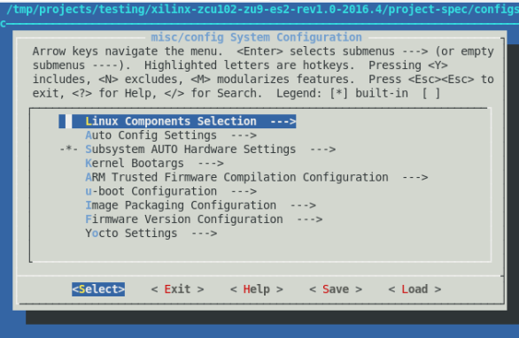 |
| Figure: Petalinux System Configuration Menu |
3. Exit and Save the new configuration.
This might take a while to apply the new configuration to the BSP.
Build the images for the ZCU102 board.
1. After the tools and BSP are setup compile the images by typing the following command in the Linux terminal.
a. For Rev 1.0 board with Production Silicon run the following commands.
$ cd xilinx-zcu102-2018.1
$ petalinux-build
$ cd images/Linux
$ cd  xilinx-zcu102-zu9-es2-rev1.0-v2018.1-final
$ petalinux-build
$ cd images/Linux
2. For booting the ZCU102 using an SDcard you need a BOOT.bin file which is a packaged file which contains the fsbl, bitstream, secure-monitor and u-boot.
Create the boot binary for the ZCU102 board using the following command.
$ petalinux-package --boot --fsbl zynqmp_fsbl.elf --fpga design_1_wrapper.bit --u-boot u-boot.elf
3. Copy the boot.bin and image.ub file present in the images/linux directory to an SD card.
Insert the SDCard to the ZCU102 board and power on the ZCU102 board.
7. Building the Hardware:
This step will provide instructions on how to setup the ZCU102 board for running the design.
Setup Requirements:
Operating System: Windows or Linux.Software Installed: Vivado 2017.1.
Steps to generate Hardware Description File:
1. Unzip the ecc-design-files.zip to C:/ drive.
2. Launch Vivado 2018.1 tool.
3. In TCL console. type the following commands
a. For Rev 1.0 board with production silicon run the following commands.
cd C:/ecc-design-files/hw/
source zynqmp-ecc-design-prod.tcl
cd C:/ecc-designfiles/hw/
source zynqmp-ecc-design-es2.tcl
board run the following commands.
cd C:/ecc-designfiles/hw/
source zynqmp-ecc-design-es1.tcl
This will generate the block design and will generate the hardware until the bitstream is done.
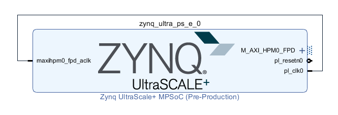 |
| Figure: ZCU102 Block Design |
4. After the bitstream has been generated close the bitstream generated Dialog box.
5. Double click on the zynq_ultra_ps_e_0 block in the block design to open the Zynq MPSoC PS Configuration Wizard.
6. Select the DDR Configuration option in the Page Navigator section of the Zynq MPSoC PS Configuration Wizard.
You should see the ECC option enabled for the DDR Controller.
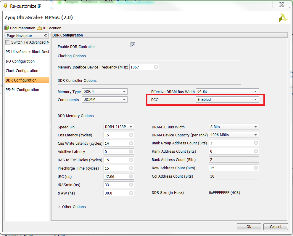 |
| Figure: ECC option enabled for DDR controller |
7. Close the wizard without making changes by clicking on Cancel.
8. Export the Hardware to SDK. In Vivado GUI , Select File > Export Hardware.
This will launch the Export Hardware dialog box.
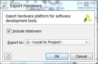 |
| Figure: Exporting Hardware to SDK |
9. Select the Include bitstream Option and click on OK.
The exported hardware should be present in "C:\ecc-designfiles\hw\ecc_design\ecc_design.sdk" directory.
8. ZCU102 Board Setup:
The following instructions will provide the steps to setup the ZCU102 board for running the design..
1. Connect the Micro USB cable into the ZCU102 Board Micro USB port J83, and the other end into an open USB port on the windows PC. This cable will be used for UART over USB communication.
2. Insert SD card into the SD card slot J100.
3. Set the SW6 switch to SD boot mode as shown below.
a. The below figure shows SD boot mode settings for ZCU102 Rev-B/C/D board
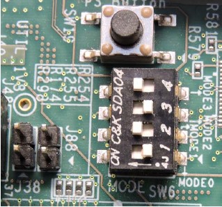 |
| Figure: SD boot mode switch setting for ZCU102 Rev A/B/C/D boards |
b.The below figure shows SD boot mode settings for ZCU102 Rev-1.0 board
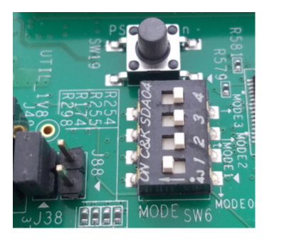 |
| Figure: Switch SW6 settings for selecting SD bootmode for ZCU102 Rev 1.0 baord |
4. Connect 12V Power to the ZCU102 6-Pin Molex connector.
5. The following figure shows the ZCU102 board with all the required connections.
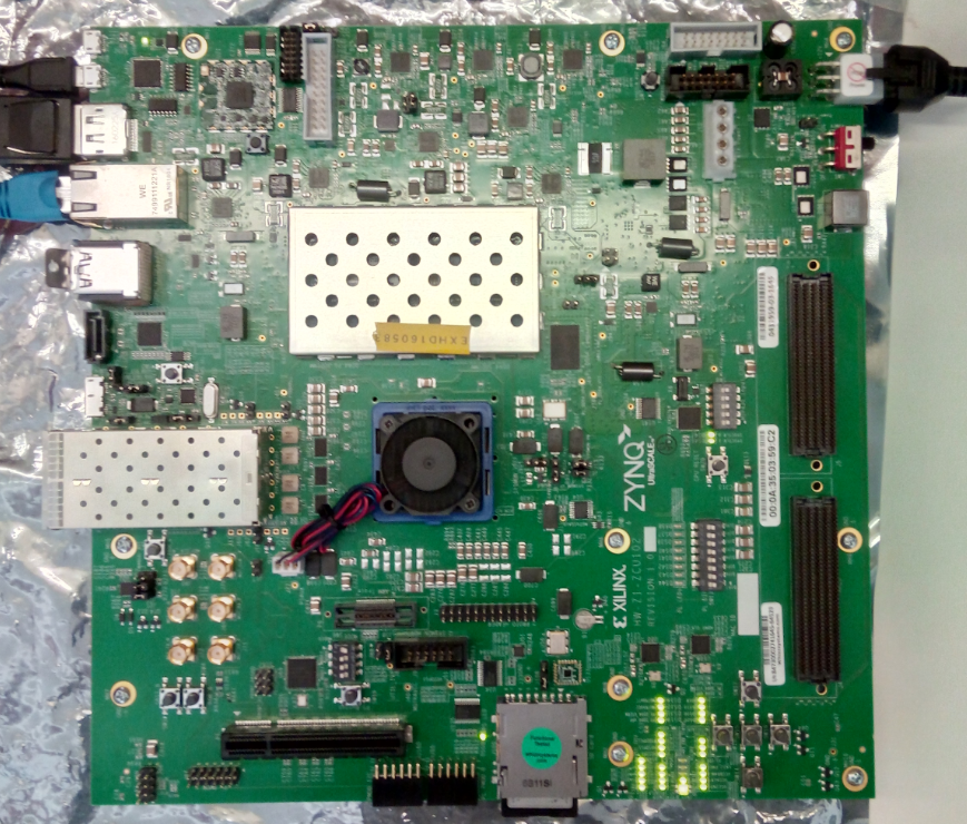 |
| Figure: ZCU102 Board setup |
Demo Execution:
1. Switch on the ZCU102 Board at SW1 (red switch). Note: Make sure that any one of the serial console utility ( Example: Tera term , putty ) is installed on the the windows machine to which UART cable is connected.This Tech tip exercises with Tera Term.
2. Connect the Tera Term with the interface 0 of the UART bridge like as shown in the below figure.
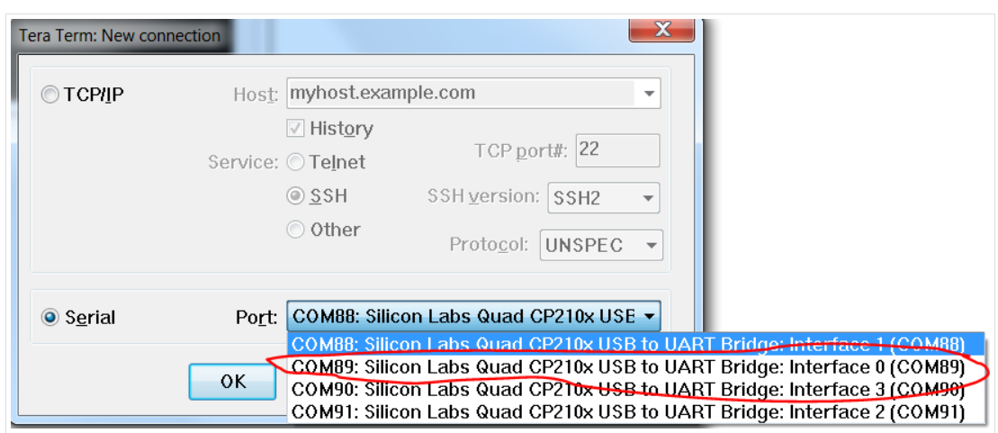 |
| Figure: Serial communication port selection |
3. After the Linux is boots up ,Login prompt appears. Enter the login with the username and password as "root".
9. Conclusion:
This reference design has shown both the ECC capabilities of the Zynq UltraScale+ MPSOC along with the software support provided by XilinxPlease refer to the Zynq MPSoC Technical Reference Manual for more information on the Zynq MPSoC Architecture.
, multiple selections available, Use left or right arrow keys to navigate selected items
© Copyright 2019 - 2022 Xilinx Inc. Privacy Policy