Zynq UltraScale+ MPSoC Base TRD 2019.2 - Design Module 3
Table of Contents
Design Overview
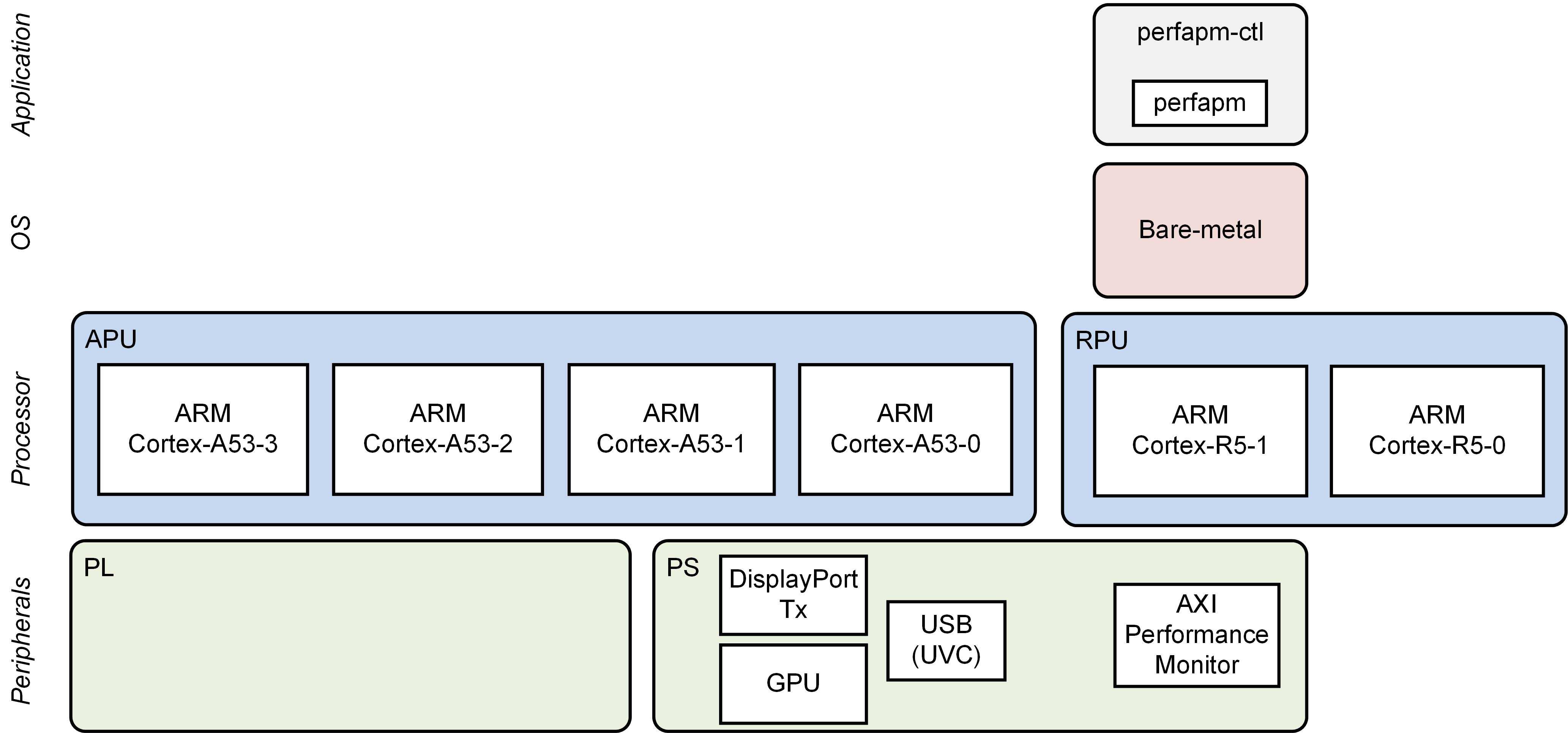
This module demonstrates:
- Boot RPU1 only
- RPU1 OS: Bare-metal
- Bare-metal performance monitor application
- Reads PS APM counters to measure CCI, Core Switch and DDR throughput and latency, then prints them to UART1
Design Components
This module requires the following components:
- petalinux_bsp
- perfapm-ctl
Build Flow Tutorials
This tutorial uses both Vitis and PetaLinux tools. It is recommended to use separate shells for each of the tools.
Perfapm-ctl Application
Create a new Vitis workspace.
% cd $TRD_HOME/workspaces/ws_perfapm-ctl
% xsdk -workspace . &
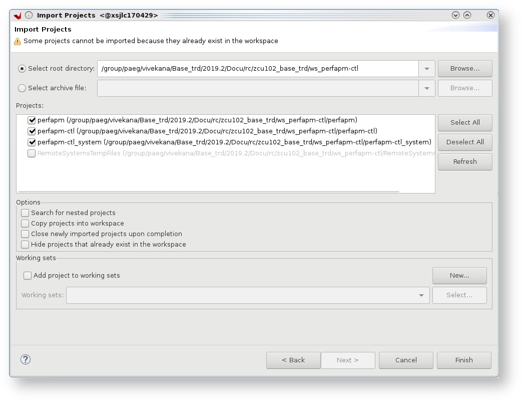
- Click 'Import Project' from the welcome screen, Choose 'Eclipse workspace' and select next.
- Uncheck 'copy projects into workspace', browse to the current working directory and make sure the
perfapm,perfapm-ctland
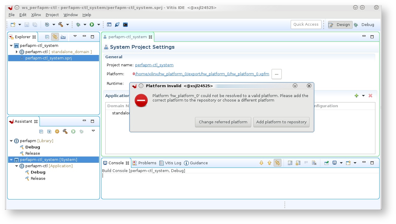
- Double click on 'perfapm-ctl_system.sprj' and close the dialog box for platform.
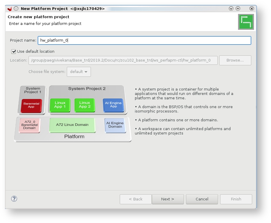
- from the top menu tab choose 'File' → 'New platform', enter Project name as 'hw_platform_0' and select 'Next'.
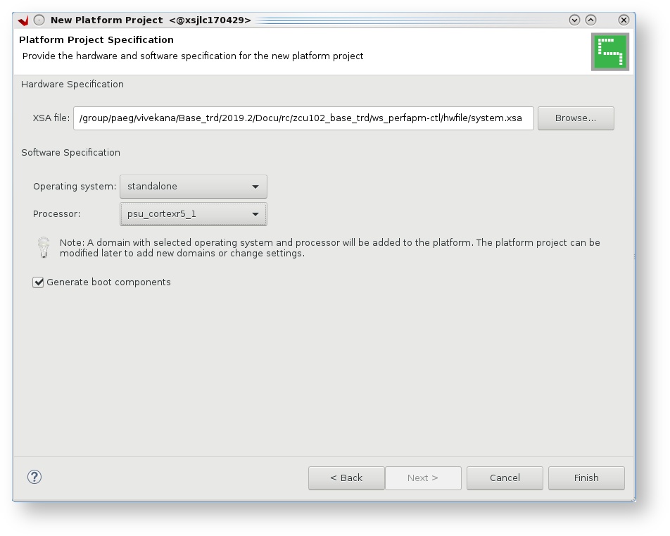
- Choose 'Create from hardware specification (XSA)' and browse to the xsa file in the 'hwfile' directory of 'ws_heartbeat workspace',
- Select operating system as 'standalone' and processor as 'psu_cortexr5_1' and click Finish.
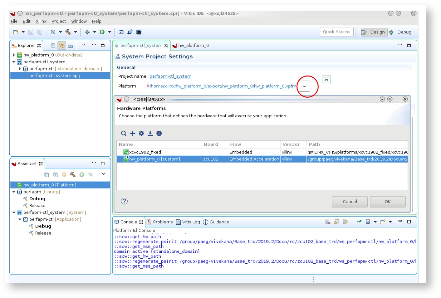
- In the System Project Settings tab, Add the new custom platform generated from xsa. Click Yes on the dialog box, when prompted to change the platform.
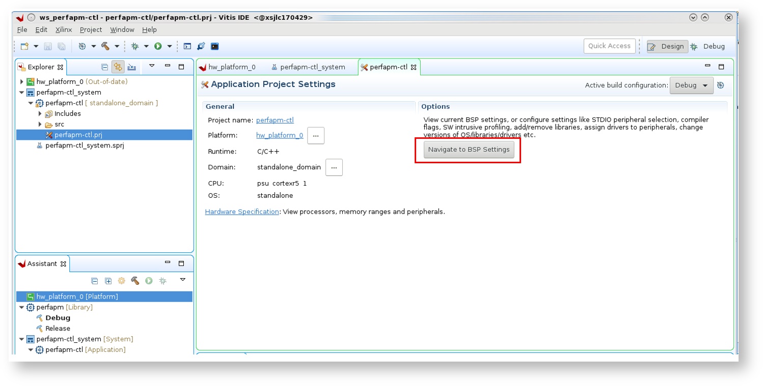
- double click on 'perfapm-ctl.prj' in the Elplorer tab, and click 'Navigate to BSP settings'
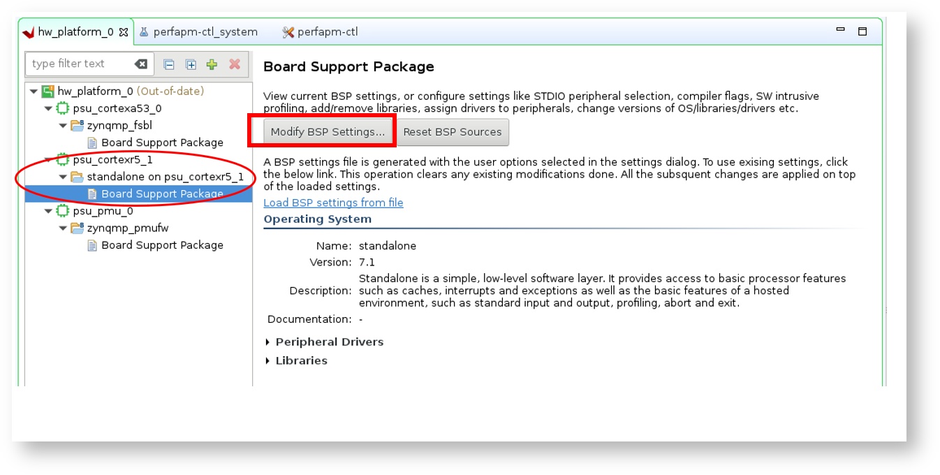
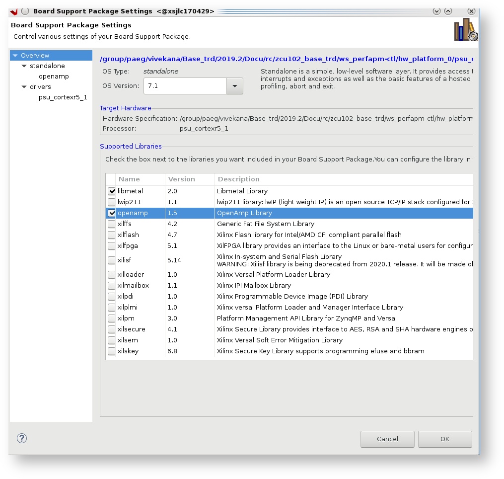
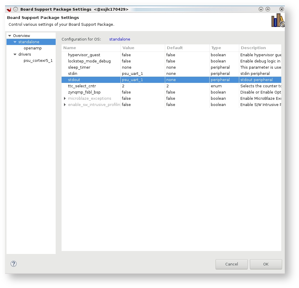
- modify BSP settings for Cortexr5_1 processor
- under overview panel enable libraries 'libmetal' and 'openamp'.
- under standalone sttings modify 'stdin/stdout' to 'psu_uart_1', select ok.
- Right-click on the
perfapm-ctlsystem and select 'Build Project'.

- Copy the generated
perfapm-ctlexecutable into the PetaLinux BSP.
% cp perfapm-ctl/Debug/perfapm-ctl.elf $TRD_HOME/petalinux/bsp/images/linux
PetaLinux BSP
This tutorial shows how to build a boot image that includes the
perfapm-ctl application using the PetaLinux build tool. This step assumes you have run through the PetaLinux build in DM1 previouslyCreate a boot image
% cd $TRD_HOME/petalinux/bsp/images/linux
% petalinux-package --boot --bif=../../project-spec/boot/dm3.bif --force
Copy the generated boot image to the dm3 SD card directory
% mkdir -p $TRD_HOME/sd_card/dm3
% cp BOOT.BIN $TRD_HOME/sd_card/dm3
Run Flow Tutorial
- See here for board setup instructions.
- Copy all the files from the
$TRD_HOME/sd_card/dm3SD card directory to a FAT formatted SD card. - Power on the board to boot the images; make sure all power rail LEDs are lit green (Note: DS1 / FPGA_INIT_B LED remains Red as there is no bit stream to configure the FPGA).
- The user can now see FSBL prints on UART-0 and prints from bare-metal
perfapm-ctlapplication can be viewed on UART-1. When prompted, user need to press 'Y' to turn on a dummy traffic generator that reads from OCM
Turn on traffic generator? Enter 'Y' or 'N':
View the application prints on UART-1 as shown in the pictures:
|----------------------------------------------------------------------|
|                      Performance Monitor APP                         |
|----------------------------------------------------------------------|
|Slot                |Write Byte Cnt |Read Byte Cnt |Total RW Byte Cnt |
|----------------------------------------------------------------------|
|DDR Slot1           |             0 |            0 |                0 |
|DDR Slot2           |             0 |            0 |                0 |
|DDR Slot3           |             0 |            0 |                0 |
|DDR Slot4           |             0 |            0 |                0 |
|DDR Slot5           |             0 |            0 |                0 |
|OCM APM             |             0 |        20480 |                0 |
|LPD_FPD             |             0 |          320 |                0 |
|----------------------------------------------------------------------|
Next Steps
- Continue with Design Module 4.
- Return to the Design Tutorials Overview.
© Copyright 2019 - 2022 Xilinx Inc. Privacy Policy