Zynq UltraScale+ MPSoC Base TRD 2019.2 - Design Module 8
Table of Contents
Design Overview
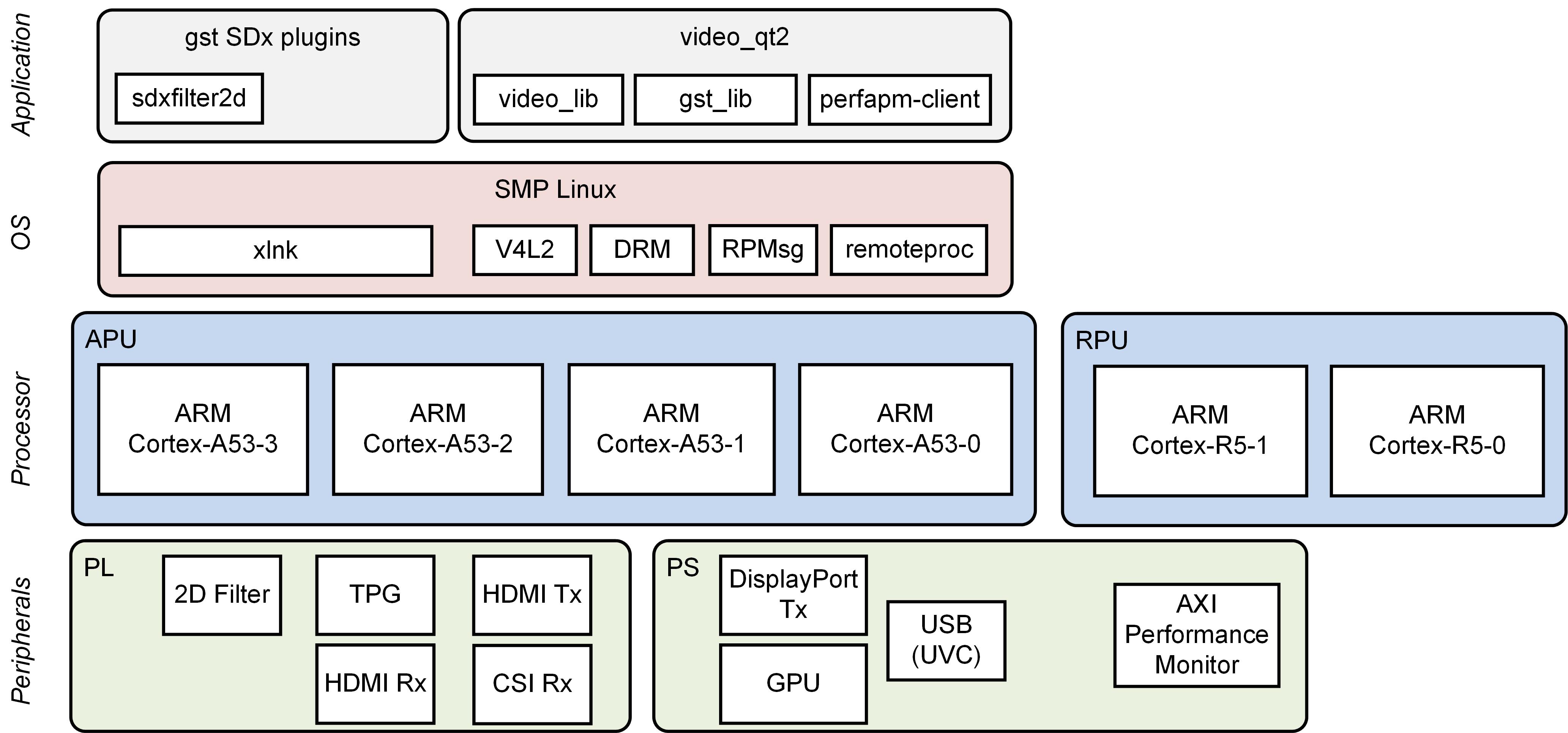
This module shows how to move the 2D convolution filter from software to hardware using the PL optimized xfopencv library that provides an OpenCV equivalent function.
Design Components
This module requires the following components:
- zcu102_base_trd (Vitis platform)
Build Flow Tutorials
2D Filter Accelerator
This tutorial shows how to build the 2D filter accelerator with HW acceleration based on the Base TRD Vitis platform.
- setup the environment by sourcing the vitis and xilinx runtime (xrt) tools.
Build the project using the make file.This can take several hours.
% cd $TRD_HOME/zcu102_base_trd/samples/filter2d/
% make VITIS_PLATFORM=$TRD_HOME/zcu102_base_trd/zcu102_base_trd.xpfm XFOPENCVDIR=$TRD_HOME/zcu102_base_trd/sw/zcu102_base_trd/a53_linux/inc/xfopencv SYSCONFIG=zcu102_base_trd  PPC=XF_NPPC1
- make will create the accelerated filter2d platform and outputs the xclbin, boot image and image.ub in the sdcard.
Copy the generated SD card image once the build is finished.
% cp -r ./sd_card $TRD_HOME/sd_card/dm8
Run Flow Tutorial
- See here for board setup instructions.
- Copy all the files from the
$TRD_HOME/sd_card/dm8SD card directory to a FAT formatted SD card. - Power on the board to boot the images; make sure INIT_B, done and all power rail LEDs are lit green.
- After ~30 seconds, the display will turn on and the application will start automatically, targeting the max supported resolution of the monitor (one of 3840x2160 or 1920x1080 or 1280x720). The application will detect whether DP Tx or HDMI Tx is connected and output on the corresponding display device.
To re-start the TRD application with the max supported resolution, run
% run_video.sh
To re-start the TRD application with a specific supported resolution use the -r switch e.g. for 1920x1080, run
% run_video.sh -r 1920x1080
- The user can now control the application from the GUI's control bar (bottom) displayed on the monitor.
- The user can select from the following video source options:
- TPG (SW): virtual video device that emulates a USB webcam purely in software
- USB: USB Webcam using the universal video class (UVC) driver
- TPG (PL): Test Pattern Generator implemented in the PL
- HDMI: HDMI input implemented in the PL
- CSI: MIPI CSI image sensor input implemented in the PL
- File: Raw video file source
- The user can select from the following accelerator options:
- Passthrough (no accelerator)
- 2D convolution filter with configurable coefficients
- The supported accelerator modes depend on the selected filter:
- SW - accelerator is run on A53
- HW - accelerator is run on PL
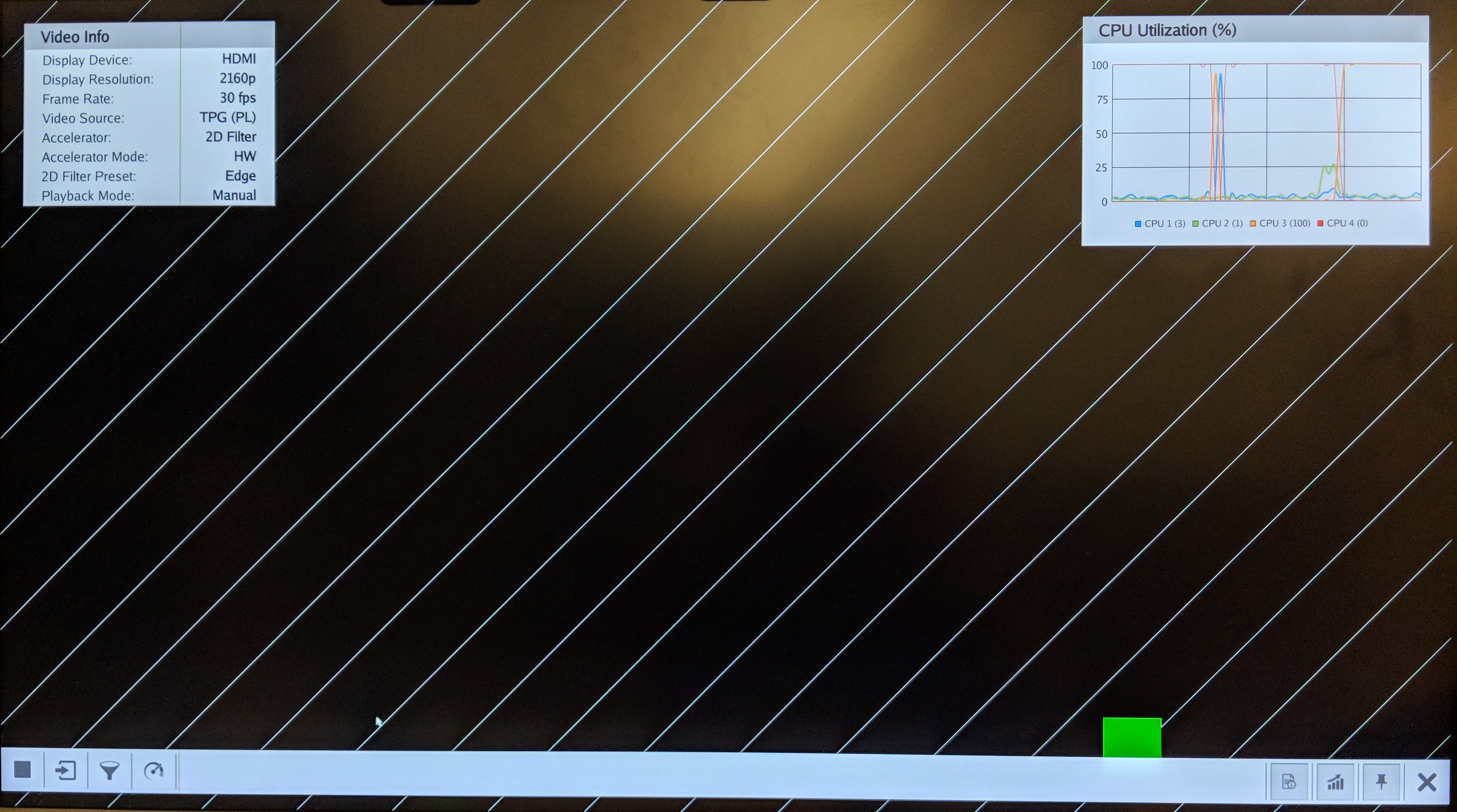
- The video info panel (top left) shows essential settings/statistics.
- The CPU utilization graph (top right) shows CPU load for each of the four A53 cores.
Next Steps
- Continue with Design Module 9.
- Return to the Design Tutorials Overview.
© Copyright 2019 - 2022 Xilinx Inc. Privacy Policy