/
Prepare Boot Medium
Prepare Boot Medium
- Confluence Wiki Admin (Unlicensed)
- Terry O'Neal (Unlicensed)
Owned by Confluence Wiki Admin (Unlicensed)
Table of Contents
SD Boot
Input Files Required
orOutput Files Produced
- bootable SD card
Task Description
The following instructions are taken from the OMAPPedia wiki.The following instructions assume a Linux system. Furthermore, most commands require root permissions. After completing this steps the SD card holds two partitions which can be read/written under Linux. Windows can - if at all - only access the FAT partition; but even this seems to depend on the card reader/driver used.
Insert SD card and figure out the corresponding device. The last lines of the dmesg output should tell you under which device file the inserted SD card is available in the system.
dmesg
Warning: The following commands will use '/dev/sdX' to refer to the SD card device. Replace this with the actual device on your system. Executing the following commands on the wrong device may corrupt your data on other file systems. Also, all data on your SD card will be destroyed.
The fdisk utility does not seem to erase the first few bytes of the first sector in the card when the partition table is saved. Use dd to erase the first sector.
dd if=/dev/zero of=/dev/sdX bs=1024 count=1
Calculate the new_cylinders value
fdisk -l /dev/sdX
Disk /dev/sdb: 8068 MB, 8068792320 bytes
249 heads, 62 sectors/track, 1020 cylinders, total 15759360 sectors
Units = sectors of 1 * 512 = 512 bytes
Sector size (logical/physical): 512 bytes / 512 bytes
I/O size (minimum/optimal): 512 bytes / 512 bytes
Disk identifier: 0x00000000

Disk /dev/sdb doesn't contain a valid partition table
Look for the size of the device in bytes and calculate the new number of cylinders using the following formula, dropping all fractions:
new_cylinders = <size> / 8225280
For the example output given above, we would write down new_cylinders = 8068792320 / 8225280 = 980
Partition the SD card. We will create two partitions on the SD card. One 200 MB sized boot partition. And a second partition taking the remaining space on the SD card.
fdisk /dev/sdX
The dd command should have wiped all existing partition tables, if this is not the case, delete all existing partitions on the SD card.
Command (m for help):
Partition number (1-4): 1
Now configure the sectors, heads and cylinders of the SD card.
Command (m for help): x
Expert command (m for help): h
Number of heads (1-256, default 30): 255
Expert command (m for help): s
Number of sectors (1-63, default 29): 63
Expert command (m for help): c
Number of cylinders (1-1048576, default 2286): <new_cylinders calculated from above>
Command (m for help): r
Now the actual partitions can be created
Command (m for help): n
Partition type:
 p primary (0 primary, 0 extended, 4 free)
 e extended
Select (default p): p
Partition number (1-4, default 1): 1
First sector (2048-15759359, default 2048):
Using default value 2048
Last sector, +sectors or +size{K,M,G} (2048-15759359, default 15759359): +200M

Command (m for help): n
Partition type:
 p primary (1 primary, 0 extended, 3 free)
 e extended
Select (default p): p
Partition number (1-4, default 2): 2
First sector (411648-15759359, default 411648):
Using default value 411648
Last sector, +sectors or +size{K,M,G} (411648-15759359, default 15759359):
Using default value 15759359
Now, set the bootable flag and partition IDs
Command (m for help): a
Partition number (1-4): 1

Command (m for help): t
Partition number (1-4): 1
Hex code (type L to list codes): c
Changed system type of partition 1 to c (W95 FAT32 (LBA))

Command (m for help): t
Partition number (1-4): 2
Hex code (type L to list codes): 83
Check the new partition table and write the changes
Command (m for help): p

Disk /dev/sdb: 8068 MB, 8068792320 bytes
249 heads, 62 sectors/track, 1020 cylinders, total 15759360 sectors
Units = sectors of 1 * 512 = 512 bytes
Sector size (logical/physical): 512 bytes / 512 bytes
I/O size (minimum/optimal): 512 bytes / 512 bytes
Disk identifier: 0x920c958b

 Device Boot Start End Blocks Id System
/dev/sdb1 * 2048 411647 204800 c W95 FAT32 (LBA)
/dev/sdb2 411648 15759359 7673856 83 Linux

Command (m for help): w
The partition table has been altered!

Calling ioctl() to re-read partition table.

WARNING: If you have created or modified any DOS 6.x
partitions, please see the fdisk manual page for additional
information.
Syncing disks.
Create file systems on the new partitions
mkfs.vfat -F 32 -n boot /dev/sdX1
mkfs.ext4 -L root /dev/sdX2
Mount the boot partition
mkdir -p /mnt/boot
mount /dev/sdX1 /mnt/boot
Copy the boot.bin or contents of the release archive to the SD card, e.g.
cp boot.bin /mnt/boot/
Unmount the SD card
umount /mnt/boot
The SD card can now be removed and transferred over to the target platform.
Configure Boot Mode
To boot from SD card the boot mode pins have to be configured accordingly, as shown in the image below.zc702 & zc706
 |
| SD boot mode switch setting |
The picture shows a zc702, but the same switch positions apply to the zc706.
JTAG Boot
Tools Required
Input Files Required
The required input files can be obtained from a provided release or build from source.Task Description
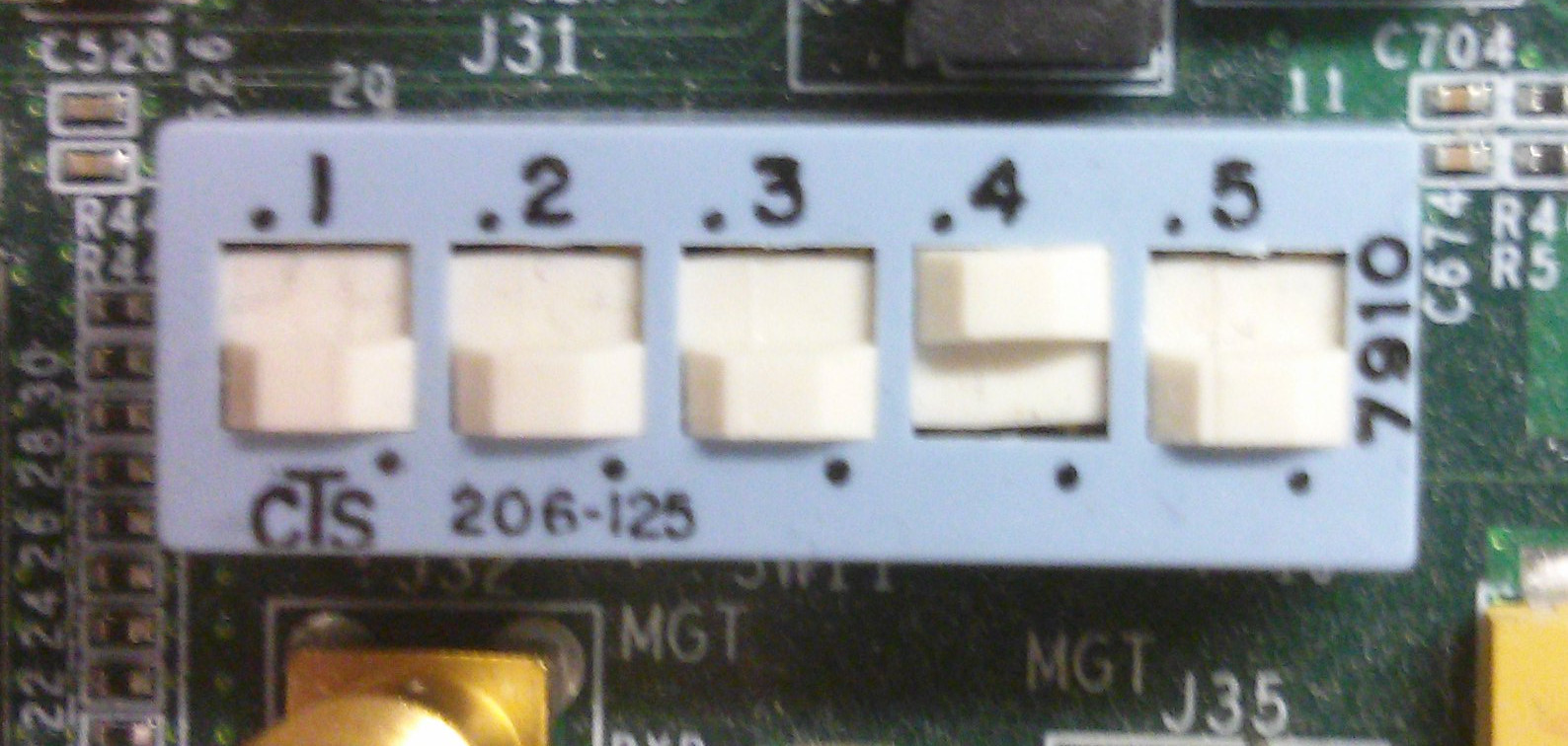
Configure boot modeTo boot from JTAG the boot mode pins have to be configured accordingly, as shown in the image below.
zc702 & zc706
 |
| A zc706 configured for JTAG boot |
Additionally the correct JTAG mode has to be selected, according to the used interface. The JTAG mode is controlled by switch SW10 on the zc702 and SW4 on the zc706. The settings are listed in the following table.
| JTAG Mode | Switch 0 | Switch 1 |
| Invalid | off | off |
| Digilent USB JTAG | off | on |
| Xilinx Platform Cable | on | off |
| 20-pin Header | on | on |
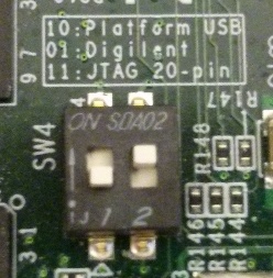 |
| SW4 on a zc706 set to use Digilent USB JTAG |
Connect the JTAG debugger to the processor
xmd% connect arm hw
Download and run the FSBL
xmd% dow fsbl.elf
xmd% con
# wait a little while
xmd% stop
Download the Linux image
xmd% dow -data devicetree.dtb 0x2a00000
xmd% dow -data uramdisk.image.gz 0x2000000
xmd% dow -data uImage 0x3000000
Download and run U-Boot
xmd% dow u-boot
xmd% con
This executes U-Boot, which will try booting the system. Interrupt U-Boots automatic boot attempt and boot the system with
u-boot> bootm 0x3000000 0x2000000 0x2a000000
Scripting JTAG Boot
The whole process of booting Linux can be done by a simple script for xmd. The only requirement for this is, that the default action U-Boot executes for JTAG boot is executing 'bootm' with addresses matching those from the 'dow -data' commands. To achieve this alignment it might be necessary build a custom U-Boot.U-Boot's default action for JTAG boot should be
bootm <uImage address> <uramdisk address> <devictree blob address>
Then a script with the following content would download and boot Linux
connect arm hw -debugdevice cpunr 1
dow fsbl.elf
con
exec sleep 3
stop
dow -data devictree.dtb <devicetree blob address>
dow -data uramdisk.image.gz <uramdisk address>
dow -data uImage <uImage address>
dow u-boot.elf
con
The script can be executed in xmd with
xmd% source <script name>
QSPI Boot
Tools Required
Input Files Required
The required input files can be obtained from a provided release or build from source.Task Description
To boot from QSPI a boot.bin must be written to the flash memory. This can happen in various ways, a few examples are given below.Program the QSPI through zynq_flash Tool
The tool zynq_flash can be used to program the QSPI on Zynq platforms (alternatively the flash can be programmed through other flows, e.g. using U-Boot or Linux). Zynq_flash requires a working JTAG connection to the board.The correct JTAG mode has to be selected, according to the used interface. The JTAG mode is controlled by switch SW10 on the zc702 and SW4 on the zc706. The settings are listed in the following table.
| JTAG Mode | Switch 0 | Switch 1 |
| Invalid | off | off |
| Digilent USB JTAG | off | on |
| Xilinx Platform Cable | on | off |
| 20-pin Header | on | on |
|
| SW4 on a zc706 set to use Digilent USB JTAG |
Once the JTAG connection is set up, the flash can be programmed by running
$ zynq_flash -f boot.bin
Program the QSPI through U-Boot
To use this method, U-Boot must be booted through some way and the boot.bin must reside in DDR memory. From that state the QSPI can be programmed from U-Boot using the following command sequence:u-boot> sf probe 0 0 0 u-boot> sf erase 0 <boot_image_size>+ u-boot> sf write <boot_image_address> 0 <boot_image_size>
Program the QSPI through Linux
To use this method, Linux must be booted through some way, the boot.bin must reside on the file system and the flashcp utility (part of mtd-utils) must be available. Furthermore, MTD partitions must be defined. The boot image needs to be written to the beginning of the flash memory. The list of partitions can be obtained through$ cat /proc/mtd
From that state the QSPI can be programmed from Linux using the following command sequence:
$ flashcp boot.bin /dev/mtd0
Set Bootmode
After the is programmed the boot mode should be changed to QSPI by setting the boot mode pins accordingly, as shown below for some example platforms.zc702 & zc706
 |
| Boot mode set for QSPI boot on a zc706 |
After power cycling the board, it will boot from the image in QSPI
Build Steps
- Fetch Sources
- Build FSBL
- Build Device Tree Compiler (DTC)
- Build PMU Firmware
- Build Arm Trusted Firmware (ATF)
- Build U-Boot
- Build and Modify a Root File System
- Build Device Tree Blob
- Build Linux Kernel
- Prepare Boot Image
- (You are here) Prepare Boot Medium
- Setup a Serial Console
- Additional Information: Build Qt and Qwt Libraries
Related Links
, multiple selections available,
Related content
Prepare boot image
Prepare boot image
More like this
Build U-Boot
Build U-Boot
Read with this
How to format SD card for SD boot
How to format SD card for SD boot
More like this
Board bring up using pre-built images
Board bring up using pre-built images
Read with this
Booting Certified Ubuntu for Xilinx Devices
Booting Certified Ubuntu for Xilinx Devices
More like this
Boot Images
Boot Images
Read with this
© Copyright 2019 - 2022 Xilinx Inc. Privacy Policy