Table of Contents
What is device tree?
Linux uses the DT basically for platform identification, run-time configuration like bootargs and the device node population.
Device tree basics
Each driver or a module in the device tree is defined by the node and all its properties are defined under that node. Based on the driver it can have child nodes or parent node.For example a device connected by SPI bus will have SPI bus controller as its parent node and that device will be one of the child node of spi node. Root node is the parent for all the nodes.
Under the root node typically consists of
1) CPUs node information
2) Memory information
3) Chosen can have configuration data like the kernel parameters string and the location of an initrd image
4) Aliases
5) Nodes which define the buses information
Device tree syntax example
/ {
    compatible = "xlnx,zynqmp";
    #address-cells = <2>;
    #size-cells = <2>;

    cpus {
       #address-cells = <1>;
       #size-cells = <0>;

       cpu0: cpu@0 {
                compatible = "arm,cortexa53", "arm,armv8";
                device-type = "cpu";
                enable-method = "psci";
                operating-points-v2 = <&cpu_opp_table>;
                reg = <0x0>;
                cpu-idle-states = <&CPU_SLEEP_0>;
        };

        cpu1: cpu@1 {
               compatible = "arm,cortexa53", "arm,armv8";
               device-type = "cpu";
               enable-method = "psci";
               operating-points-v2 = <&cpu_opp_table>;
               reg = <0x1>;
               cpu-idle-states = <&CPU_SLEEP_0>;
        };
  };

  chosen {
           bootargs = "earlycon clk_ignore_unused";
  };

  memory {
          device-type = "memory";
          reg = <0x0 0x0 0x0 0x80000000>, <0x00000008 0x0 0x0 0x80000000>;
  };

  amba_apu: amba_apu@0 {
              compatible = "simple-bus";
              #address-cells = <2>;
              #size-cells = <1>;
              ranges = <0 0 0 0 0xffffffff>;
              gic: interrupt-controller@f9010000 {
                        compatible = "arm,gic-400", "arm,cortex-a15-gic";
                        #interrupt-cells = <3>;
                        reg = <0x0 0xf9010000 0x10000>,
                               0x0 0xf9020000 0x20000>,
                               0x0 0xf9040000 0x20000>,
                               0x0 0xf9060000 0x20000>,
                        interrupt-controller;
                        interrupt-parent = <&gic>;
                        interrupts =<1 9 0xf04>;
              };
  };

  amba: amba {
          compatible = "simple-bus";
          #address-cells = <2>;
          #size-cells = <2>;
          ranges;
          can0: can@ff060000 {
                     compatible = "xlnx,zynq-can-1.0";
                     clock-names = "can_clk", "pclk";
                     reg =<0x0 0xff060000 0x0 0x1000>;
                     interrupts = <0 23 4>;
                     interrupt-parent = <&gic>;
                     tx-fifo-depth = <0x40>;
                     rx-fifo-depth = <0x40>;
                     power-domains = <&pd_can0>;
          };
  };
Device tree properties
compatible: The top-level compatible property typically defines a compatible string for the board, and then for the SoC.Values always given with the most-specific first, to least-specific last.
#address-cells: Property indicate how many cells (i.e 32 bits values) are needed to form the base address part in the reg property.
#size-cells: The size part of the reg property.
interrupt-controller: Is a boolean property that indicates that the current node is an interrupt controller.
#interrupt-cells: Indicates the number of cells in the interrupts property for the interrupts managed by the selected interrupt controller.
interrupt-parent: Is a phandle that points to the interrupt controller for the current node. There is generally a top-level interrupt-parent definition for the main interrupt controller.
Microprocessor software specification(MSS) file
The MSS file contains directives for customizing operating systems (OSs), libraries, and drivers.Microprocessor Driver Definition(MDD) file
An MDD file contains directives for customizing software drivers.Each device driver has an MDD file and a Tcl file associated with it. The MDD file is used by the Tcl file to customize the driver, depending on different options configured in the MSS file.
The driver source files and the MDD file for each driver must be located at specific directories in order to find the files and the drivers.
Driver Definition Files
Driver Definition involves defining a Data Definition file (MDD) and a Data Generation file (Tcl file).Data Definition File: The MDD file (<driver_name>.mdd) contains the configurable parameters.
Data Generation File: The second file (<driver_name>.tcl, with the filename being the same as the MDD filename) uses the parameters configured in the MSS file for the
driver to generate data.
How to add a new driver to the DTG
1. Sync the repo https://github.com/xilinx/device-tree-xlnx2. Create a folder with the driver name say for example axi_iic device-tree-xlnx/axi_iic/
3. Add the file data under axi_iic like device-tree-xlnx/axi_iic/data/
4. Create the files axi_iic.mdd and axi_iic.tcl under device-tree-xlnx/axi_iic/data/axi_iic.mdd axi_iic.tcl
5. The syntax for the file axi_iic.mdd is as
OPTION psf_version = 3.0;

BEGIN driver axi_iic
OPTION supported_peripherals = (axi_iic);--> the axi_iic is the IP_NAME which we get from the HDF file.
OPTION supported_os_types = (DTS);
OPTION driver_state = ACTIVE;
OPTION NAME = axi_iic;
END drive
6. The syntax for the file axi_iic.tcl where you can have the properties which need to be set based on the some condition will be defined
We use HSI APIs to update the node properities. The below we update the clock property for axi_iic calling a generic function as below
if {[string match -nocase $proctype "psu_cortexa53"] } {
	update_clk_node $drv_handle "s_axi_aclk"
}
7. The generated node in the pl.dtsi should be as below
io_bd_iic_0: i2c@a1200000 {
	#address-cells = <1>;
	#size-cells = <0>;
	clock-names = "s_axi_aclk";
	clocks = <&misc_clk_0>;
	compatible = "xlnx,xps-iic-2.00.a";
	interrupt-names = "iic2intc_irpt";
	interrupt-parent = <&gic>;
	interrupts = <0 2 4>;
	reg = <0x0 0xa1200000 0x0 0x10000>;
};
List of drivers supported in the DTG and their bindings in Linux tree
- can, canfd
- axi_cdma
- axi_dma
- axi_emc
- axi_ethernet, axi_10g_ethernet,xxv_ethernet
- axi_gpio
- axi_iic
- axi_pcie,axi_pcie3,xdma
- axi_perf_mon
- axi_quad_spi
- axi_sysace
- axi_tft
- axi_timebase_wdt
- axi_traffic_gen
- axi_usb2_device
- vcu
- axi_vdma
- xadc_wiz
- axi_intc
- ddr4,ddr3,mig_7series
- pr_decoupler
- usp_rf_data_converter
- axi_timer
- tsn_endpoint_ethernet_mac
- axi_uartlite
- axi_uart16550
- framebuf_rd/framebuf_wr
Bindings from the Linux tree https://github.com/Xilinx/linux-xlnx/blob/master/Documentation/devicetree/bindings/dma/xilinx/xilinx_frmbuf.txt - sdi_rx subsystem Bindings from the Linux tree https://github.com/Xilinx/linux-xlnx/blob/master/Documentation/devicetree/bindings/media/xilinx/xlnx%2Csdirxss.txt
- mipi csi2 rx subsystem Bindings from the Linux tree https://github.com/Xilinx/linux-xlnx/blob/master/Documentation/devicetree/bindings/media/xilinx/xlnx%2Ccsi2rxss.txt
- demosaic Bindings from the Linux tree https://github.com/Xilinx/linux-xlnx/blob/master/Documentation/devicetree/bindings/media/xilinx/xlnx%2Cv-demosaic.txt
- gamma Bindings from the Linux tree https://github.com/Xilinx/linux-xlnx/blob/master/Documentation/devicetree/bindings/media/xilinx/xlnx%2Cv-gamma-lut.txt
- multiscaler Bindings from the Linux tree https://github.com/Xilinx/linux-xlnx/blob/master/Documentation/devicetree/bindings/media/xilinx/xlnx%2Cv-multi-scaler.txt
- scaler Bindings from the Linux tree https://github.com/Xilinx/linux-xlnx/blob/master/Documentation/devicetree/bindings/media/xilinx/xlnx%2Cv-scaler.txt
- scene change detector Bindings from the Linux tree https://github.com/Xilinx/linux-xlnx/blob/master/Documentation/devicetree/bindings/media/xilinx/xlnx%2Cv-scd.txt
- video timing controller(vtc) Bindings from the Linux tree https://github.com/Xilinx/linux-xlnx/blob/master/Documentation/devicetree/bindings/media/xilinx/xlnx%2Cv-tc.txt
- video test pattern generator(TPG) Bindings from the Linux tree https://github.com/Xilinx/linux-xlnx/blob/master/Documentation/devicetree/bindings/media/xilinx/xlnx%2Cv-tpg.txt
- color space converter(CSC) Bindings from the Linux tree https://github.com/Xilinx/linux-xlnx/blob/master/Documentation/devicetree/bindings/media/xilinx/xlnx%2Cv-vpss-csc.txt
- vpss scaler Bindings from the Linux tree https://github.com/Xilinx/linux-xlnx/blob/master/Documentation/devicetree/bindings/media/xilinx/xlnx%2Cv-vpss-scaler.txt
- sdi_tx subsystem Bindings from the Linux tree https://github.com/Xilinx/linux-xlnx/blob/master/Documentation/devicetree/bindings/drm/xilinx/sdi.txt
- dsi Bindings from the Linux tree https://github.com/Xilinx/linux-xlnx/blob/master/Documentation/devicetree/bindings/drm/xilinx/dsi.txt
- hdmi tx Bindings https://github.com/Xilinx/hdmi-modules/blob/master/Documentation/devicetree/bindings/xlnx%2Cv-hdmi-tx-ss.txt
- hdmi rx Bindings https://github.com/Xilinx/hdmi-modules/blob/master/Documentation/devicetree/bindings/xlnx%2Cv-hdmi-rx-ss.txt
Device tree Generation
Generally for the SOCs there will be a static dts/dtsi files, but when it comes to the FPGA there can be many complicated designs which the peripheral logic(PL) IPs may vary or might be having different configurations.
For these complicated FPGA designs we require a Device tree generator(DTG) where it can generate the dts/dtsi automatically for those designs.
Once we generate there will be different files available in the output directory
say for example dt/pl.dtsi pcw.dtsi system-top.dts zynqmp.dtsi zynqmp-clk-ccf.dtsi
1) pl.dtsi: This is a file where all the memory mapped peripheral logic(PL) IP nodes will be available.
2) pcw.dtsi: This is a file where the dynamic properties where the PS peripheral needs.
3)system-top.dts: This is a file where it contains the memory information, early console and the boot arguments.
4)zynqmp.dtsi: This file contains all the PS peripheral information and also the cpu info.
5) zynqmp-clk-ccf.dtsi: This file contains all the clock information for the peripheral IPs.
Apart from these files, based on the board it will generate one more board.dtsi file under the same output directory dt/ also
for example board is zcu111-reva then it generates dt/zcu111-reva.dtsi
6)zcu111-reva.dtsi: It contains all the board specific properties like i2c might be connected to some slave etc.
How to enable DT OVERLAY from DTG
Using HSI commands
1.Clone the device tree repo
https://github.com/Xilinx/device-tree-xlnx
2) Go to the HSI prompt
[vabbarap@xhdl3763 /proj/xhdsswstaff/vabbarap/Overlay/New_hdf> % hsi
hsi v2017.3 (64-bit)SW Build 2018833 on Wed Oct 4 19:58:07 MDT 2017
Copyright 1986-2017 Xilinx, Inc. All Rights Reserved.
3)
hsi% open_hw_design system.hdf
4)
hsi% set_repo_path /home/vabbarap/workspace/sync_dt_tip/clk_wiz_15_12_2017 (DTG repo path)
5)
hsi% create_sw_design -proc psu_cortexa53_0 sd22 -os device_tree
6)
hsi% set_property CONFIG.dt_overlay true [get_os]
7)
hsi% generate_target -dir dt/
hsi% ls dt/
pcw.dtsi pl.dtsi sd22.mss system-top.dts zynqmp-clk-ccf.dtsi zynqmp.dtsi
Using XSCT (From 2019.2 release no hsi support)
2) Go to the XSCT prompt
[issue]→xsct
****** Xilinx Software Commandline Tool (XSCT) v2020.1.0
3) hsi open_hw_design system.xsa
4) hsi set_repo_path /home/vabbarap/workspace/sync_dt_tip/dt_15_12_2019 (DTG repo path)
5) hsi create_sw_design -proc psu_cortexa53_0 sd22 -os device_tree
6)hsi generate_target -dir dt
Compiling pl.dtsi
dtc -O dtb -o pl.dtbo -b 0 -@ pl.dtsi
Device tree binarys comparision
We can check the differences between two device tree blobs(dtbs) using the dtx_diff binary as below
./scripts/dtc/dtx_diff vcu118-rev2.0.dtb vcu118-rev-new.dtb
Dependencies/ Limitations
- zynqmp-clk-ccf.dtsi has static clock node configuration, if user wants to change any of the clock information update those in system-user.dtsi.
- Multi concat Interrupt blocks wont be supported by the DTG.
- Interrupt port width more than one wont be supported.
- When multicore is enabled for the MAC IPs(if the MAC IPs are more than 1) then there is issue with the label in DTG and it fails. But there wont be an issue if the MAC IP is one and multicore is enabled.
- DTG wont support for generation of private peripheral interrupts(PPI).
- DTG supports the video pipeline generation based on the internal TRD designs as mentioned in the wiki
https://xilinx-wiki.atlassian.net/wiki/spaces/A/pages/25329832/Zynq+UltraScale+MPSoC+VCU+TRD+2018.3
- If there are any custom IPs connected between the video pipeline IPs DTG wont support those, user may need to add the input and output ports.
- For broadcaster IP the output can connect to multiple output ports and DTG cant know which output port is a valid for the correct pipeline.
- If there are multiple similar video pipelines in the design user need to add the input and output port information in the nodes.The below wiki gives someinfo about how to add the input and output ports
- DTG limitation for multimedia IPs
Build Device Tree
This how-to describes the process of compiling a device tree blob.Device Tree Blob is a part of the Xilinx design flow described in Getting Started.
Task Dependencies (Pre-requisites)
Fetch Sources (Device Tree Generator sources and Linux sources)
- Hardware Project
Tools Required
Input Files Required
- Hardware Project directory
- Linux source directory
Output Files Produced
- *.dts, *.dtsi, *.dtb
Task Description
Creating a Device Tree Source (.dts/.dtsi) files (Vivado 2014.2 onwards)
Generate HDF file from hardware project
- Open the hardware project in Vivado.
- Generate Block Design
IP Integrator: Generate Block Design
# Export the hardware system to SDK:
Vivado Menu: File > Export > Export Hardware
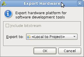 (In <project_name>.sdk HDF file is generated)
Generate a Device Tree Source (.dts/.dtsi) files from SDK
Open SDK from Vivado or open SDK via command line (xsdk -hwspec <filename>.hdf -workspace <workspace>
Vivado Menu: File > Launch SDK
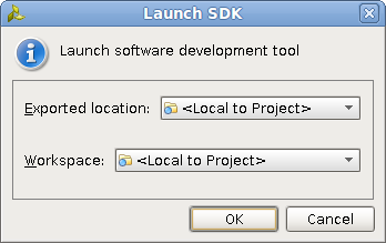
The Device Tree Generator Git repository needs to be cloned from the Xilinx. See the Fetch Sources page for more information on Git.
# Otherwise for SDK 2014.2 use this repo:
git clone git://github.com/Xilinx/device-tree-xlnx.git
Add the BSP repository in SDK (for SDK 2014.2 and later select "device-tree-xlnx" from the checked out git area):
SDK Menu: Xilinx Tools > Repositories > New... (<bsp repo>) > OK
Create a Device Tree Board Support Package (BSP):
SDK Menu: File > New > Board Support Package > Board Support Package OS: device-tree > Finish
- A BSP settings window will appear. This window can also be accessed by opening the Device Tree BSP's system.mss file and clicking 'Modify this BSP's Settings'. Fill in the values as appropriate:
- The 'bootargs' parameter specifies the arguments passed to the kernel at boot time (kernel command line). ***
- The 'console device' parameter specifies which serial output device will be used. Select a value from the drop-down.
The .dts/.dtsi files are now located in <SDK workspace>/device_tree_bsp_0/ folder.
*** e.g. console=<tty>,<baudrate> root=/dev/ram rw ip=:::::eth0:dhcp earlyprintk
*** Some example values for <tty> are ttyPS0 when using Zynq, ttyUL0 when using the UART Lite soft ip, or ttyS0 when using the UART16550 soft ip.
Generate a Device Tree Source (.dts/.dtsi) files on command line using HSM/HSI
- Source Xilinx design tools
Run HSM or HSI (Vivado 2014.4 onwards)
hsm
Open HDF file
open_hw_design <design_name>.hdf
Set repository path (clone done in previous step in SDK) (On Windows use this format set_repo_path {C:\device-tree-xlnx})
set_repo_path <path to device-tree-xlnx repository>
Create SW design and setup CPU (for ZynqMP psu_cortexa53_0, for Zynq ps7_cortexa9_0, for Microblaze microblaze_0)
create_sw_design device-tree -os device_tree -proc ps7_cortexa9_0
Generate DTS/DTSI files to folder my_dts where output DTS/DTSI files will be generated
generate_target -dir my_dts
Generate a Board file Device Tree Source (.dts/.dtsi) files on command line using HSM/HSI
- Source Xilinx design tools
- Run HSM or HSI (Vivado 2014.4 onwards)
hsi
- 3. Open HDF file
open_hw_design <design_name>.hdf
- 4. Set repository path (clone done in previous step in SDK) (On Windows use this format set_repo_path {C:\device-tree-xlnx})
set_repo_path <path to device-tree-xlnx repository>
- 5. Create SW design and setup CPU (for ZynqMP psu_cortexa53_0, for Zynq ps7_cortexa9_0, for Microblaze microblaze_0)
create_sw_design device-tree -os device_tree -proc ps7_cortexa9_0
- 6. set_property CONFIG.periph_type_overrides "{BOARD zcu102-rev1.0}" [get_os]
set_property CONFIG.periph_type_overrides "{BOARD zcu102-rev1.0}" [get_os]
7. Generate DTS/DTSI files to folder my_dts where output DTS/DTSI files will be generated
generate_target -dir my_dts
Compiling a Device Tree Blob (.dtb) file from the DTS
A utility called device tree compiler (DTC) is used to compile the DTS file into a DTB file. DTC is part of the Linux source directory. linux-xlnx/scripts/dtc/ contains the source code for DTC and needs to be compiled in order to be used. One way to compile the DTC is to build the Linux tree. The DTC might also be available through your OS's package manager.Once the DTC is available, the tool may be invoked to generate the DTB:
./scripts/dtc/dtc -I dts -O dtb -o <devicetree name>.dtb <devicetree name>.dts
./scripts/dtc/dtc -I dtb -O dts -o <devicetree name>.dts <devicetree name>.dtb
Alternative: For ARM only
In the Linux source directory, making the target 'dtbs' will compile all DTS files from linux-xlnx/arch/arm/boot/dts/ into DTB files.
make ARCH=arm dtbs
A single linux-xlnx/arch/arm/boot/dts/<devicetree name>.dts may be compiled into linux-xlnx/arch/arm/boot/dts/<devicetree name>.dtb:
make ARCH=arm <devicetree name>.dtb
Custom IPs:
For Custom IPs the DTG will generate the node with "compatible" property and interrupts if any connected.
--NOTE! THIS SECTION IS OBSOLETE AND ONLY APPLIES TO SDK 2014.1 OR EARLIER.--
Creating a Device Tree Source (.dts) file for SDK 2014.1 (or earlier)
- Open the hardware project in XPS.
Export the hardware system to SDK:
- NOTE: The GitHub repository cloned in the following instructions is no longer available online. Contact your local FAE for an archived copy or request access to the Xilinx Space Lounge.
XPS Menu: Project > Export Hardware Design to SDK... > Export && Launch SDK
# The Device Tree Generator Git repository needs to be cloned from the Xilinx. See the [[www/Fetch Sources|Fetch Sources]] page for more information on Git. Note that there are two repos for differing SDK versions below.
> [[code]]
> > > > > > > > > > > > > > > > > > > > > > > > > > > > > > > > > > > > > > > > > > > > > > > > > > > > > > > > > > git clone git://github.com/Xilinx/device-tree.git bsp/device-tree_v0_00_x//
> > > > > > > > > > > > > > > > > > > > > > > > > > > > > > > > > > > > > > > > > > > > > > > > > > > > > > > > //[[code]]//
> > > > > > > > > > > > > > > > > > > > > > > > > > > > > > > > > > > > > > > > > > > > > > > > > > > > > > > > # //Note: In order for SDK to be able to import the Device Tree Generator correctly, the file and directory hierarchy needs to look like://
> > > > > > > > > > > > > > > > > > > > > > > > > > > > > > > > > > > > > > > > > > > > > > > > > > > > > > > > > //<bsp repo>/bsp/device-tree//_v0_00_x/data/device-tree_v2_1_0.mld
> > > > > > > > > > > > > > > > > > > > > > > > > > > > > > > > > > > > > > > > > > > > > > > > > > > > > > > > > //<bsp repo>/bsp/device-tree//_v0_00_x/data/device-tree_v2_1_0.tcl//
> > > > > > > > > > > > > > > > > > > > > > > > > > > > > > > > > > > > > > > > > > > > > > > > > > > > > > > > # Add the BSP repository in SDK (for SDK 2014.2 and later select "device-tree-xlnx" from the checked out git area):
> [[code]]
 > SDK Menu: Xilinx Tools > Repositories > New... (<bsp repo>) > OK
Create a Device Tree Board Support Package (BSP):
SDK Menu: File > New > Board Support Package > Board Support Package OS: device-tree > Finish
- A BSP settings window will appear. This window can also be accessed by opening the Device Tree BSP's system.mss file and clicking 'Modify this BSP's Settings'. Fill in the values as appropriate:
- The 'bootargs' parameter specifies the arguments passed to the kernel at boot time (kernel command line). ***
- The 'console device' parameter specifies which serial output device will be used. Select a value from the drop-down.
The .dts file is now located in <SDK workspace>/<device-tree bsp name>/<processor name>/libsrc/device-tree_v0_00_x/xilinx.dts.
*** e.g. console=<tty>,<baudrate> root=/dev/ram rw ip=:::::eth0:dhcp earlyprintk
*** Some example values for <tty> are ttyPS0 when using Zynq, ttyUL0 when using the UART Lite soft ip, or ttyS0 when using the UART16550 soft ip.
In the Linux source directory, there are also some DTS files available for use in linux-xlnx/arch/<architecture>/boot/dts/.
Release Notes
- 2016.4 DTG Release Notes
- http://www.wiki.xilinx.com/2017.3+Linux+and+DTG+Release+Notes
- http://www.wiki.xilinx.com/2017.4+Linux+and+DTG+Release+Notes
- http://www.wiki.xilinx.com/2018.1+Linux+and+DTG+Release+Notes
- http://www.wiki.xilinx.com/2018.2+Linux+and+DTG+Release+Notes
- 2018.3 Release Notes for Open Source Components (see DTG section)
Build Steps
Fetch Sources
- Build FSBL
- Build Device Tree Compiler (DTC)
- Build PMU Firmware
- Build Arm Trusted Firmware (ATF)
- Build U-Boot
- Build and Modify a Root File System
- (You are here) Build Device Tree Blob
- Build Linux Kernel
- Prepare Boot Image
- Prepare Boot Medium
- Setup a Serial Console
- Additional Information: Build Qt and Qwt Libraries
Related Links
Install Xilinx tools
- Build U-Boot
- Build Linux Kernel
- Updated device tree specification can be found here https://www.devicetree.org/
- https://elinux.org/Device_Tree_Usage