Zynq UltraScale+ MPSoC VCU TRD 2018.3
Table of Contents
1 Revision History
This wiki page complements the 2018.3 version of the MPSoC VCU TRD.
Change Log:
- Update all projects, IPs, and tools versions to 2018.3
- HDMI Audio integrated into TRD
- Multistream support – Maximum 8 streams (7 HDMI, 1 MIPI)
- PS GEM for stream out and stream in (capture->encode->stream-out <-> stream-in-> Decode→display)
- 10G Ethernet stream out and stream in (capture->encode->stream-out <-> stream-in-> Decode→display)
- Two new MINI reference designs added (HDMI TX and SDI TX )
- HDMI Video captures and Display with SDSoC.
2 Overview
This is the main page of VCU TRD wiki, which has links to redirect wiki pages corresponding to individual design modules. It also explains the complete feature list and the supported resources of all the designs. TRD package weblink is provided for the user to download. This page also gives information on required software tools, IP licenses.
The Zynq® UltraScale+™ MPSoC Video Codec Unit (VCU) Targeted Reference Design (TRD) consists of an embedded video encoding/decoding application that runs on the Processing System (PS). The overall functionality of the TRD is partitioned between the Processing System (PS), Video Codec Unit, and Programmable Logic (PL) for optimal performance.
The primary goal of this TRD is to demonstrate the capabilities of the VCU core which is an integrated hard block present in Zynq UltraScale+ MPSoC EV devices. The TRD serves as a platform for the user to tune the performance parameters of VCU and arrives at an optimal configuration for encoder and decoder blocks for their specific use case. The TRD uses Vivado IP Integrator (IPI) flow for building the hardware design and Xilinx Yocto PetaLinux flow for software design. It uses Xilinx IPs and software drivers to demonstrate the capabilities of different components
The TRD supports the following video interfaces:
Sources (up-to 4K-60FPS):
- Test pattern generator (TPG) implemented in the PL.
- HDMI-Rx capture pipeline implemented in the PL.
- MIPI CSI-2 Rx capture pipeline implemented in the PL.
- File source (SD card, USB storage, SATA hard disk).
- Stream-In from network or internet.
- SDI-Rx capture pipeline implemented in the PL.
Sinks (up-to 4K-60FPS for HDMI and 4K-30FPS for Display Port):
- DP Tx display pipeline in the PS.
- HDMI-Tx display pipeline implemented in the PL.
- SDI-Tx display pipeline implemented in the PL.
VCU Codec:
- Video Encode/Decode capability using VCU hard block in PL
- H.264/H.265 encoding
- Encoder/decoder parameter configuration using OMX interface
- Demonstrate multi-stream capability of VCU at 4k 60 Hz throughput
Audio Codec :
- AAC 2 channel 48KHz
Streaming Interfaces:
- 1G Ethernet PS GEM
- 10G PL Ethernet
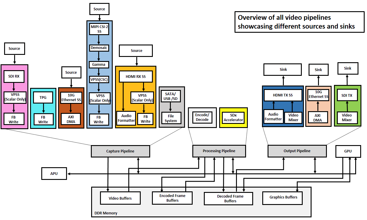
The below figure shows the TRD block diagram. It consists of all the Design Modules. The components of each design module are highlighted in unique colors in the diagram. The remaining blocks are common to all design modules as shown.
The VCU TRD 2018.3 version consists of nine design-modules as described below. Individual links below will redirect to the corresponding wiki pages and build and run flow of individual designs modules.
Design Module # | Project Name | Description |
|---|---|---|
| 1 | VCU TRD | Multi-stream design supporting HDMI-Rx, TPG, MIPI, HDMI-Tx, DP along with showcasing capabilities of VCU. |
| 2 | SDI Capture and Display | Design showcasing Video Capture and Display through SDI interface along with the capabilities of VCU |
| 3 | HDMI Audio | Design supporting Audio with HDMI-Rx and HDMI-Tx and showcasing capabilities of VCU |
| 4 | 10G Ethernet Video streaming | Design showcasing Video stream over 10G Ethernet along with the capabilities of VCU |
| 5 | 10G Ethernet Video Streaming With SDSoC accelerator | Design showcasing Video stream over 10G Ethernet by adding a PL based accelerator IP through SDSoC tool as post-processing plug-in for VCU |
6 | Design showcasing Video Capture through HDMI interface along with the capabilities of VCU | |
| 7 | HDMI Display | Design showcasing Video Display through HDMI interface along with the capabilities of VCU |
8 | Design showcasing Video Capture only through SDI interface along with the capabilities of VCU | |
9 | VCU based video design showcasing SDI transmit capabilities along with the capabilities of the VCU |
VCU TRD User guide has more details about the list of features, software architecture, and hardware architecture of individual designs. Here is the link for the user guide :
3 Software Tools and System Requirements
3.1 Hardware
Required:
- ZCU106 evaluation board (rev C/D/E/F/1.0) with power cable
- Monitor with DisplayPort/HDMI input supporting 3840x2160 resolution or 1920x1080 resolution
- Display Port cable (DP certified)
- HDMI cable
- Class-10 SD card
- GooBang Doo ABOX 2017 player with the resolution set to 4KP30, colour space to VUY24 and HDMI cable
- NVIDIA SHIELD Pro
- USB mouse
- Ethernet cable
- SFP+ optical module
- Optical fibre cable for 10G
- SDI Receiver - Black Magic Teranex Mini HDMI to 12G converter
- SDI Transmitter - Black Magic Teranex Mini 12G to HDMI converter
Optional:
- USB pen drive formatted with the FAT32 file system and hub
- SATA drive formatted with the FAT32 file system, external power supply, and data cable
- LI-IMX274MIPI-FMC image sensor daughter card
3.2 Software Tools
Required:
- Linux host machine for all tool flow tutorials (see UG1144 for detailed OS requirements)
- PetaLinux Tools version 2018.3 (see UG1144 for installation instructions)
- VIVADO Design suite version 2018.3
- Git distributed version control system
- Silicon Labs quad CP210x USB-to-UART bridge driver
- Serial terminal emulator e.g. teraterm
3.3 Download, Installation, and Licensing
The Vivado Design Suite User Guide explains how to download and install the Vivado® Design Suite tools, which includes the Vivado Integrated Design Environment (IDE), High-Level Synthesis tool, and System Generator for DSP. This guide also provides information about licensing and administering evaluation and full copies of Xilinx design tools and intellectual property (IP) products. The Vivado Design Suite can be downloaded from here.
LogiCORE IP Licensing
The following IP cores require a license to build the design.
- Video Test Pattern Generator (TPG) - Free License but must be downloaded
- Video Timing controller (VTC) - Free License but must be downloaded
- Video Mixer- Purchase license (Hardware evaluation available)
- Video PHY Controller - Included with Vivado
- HDMI-Rx/Tx Subsystem - Purchase license (Hardware evaluation available)
- Video Processing Subsystem (VPSS) - Purchase license (Hardware evaluation available)
- MIPI CSI Controller Subsystems (mipi_csi2_rx_subsystem) - Purchase license (Hardware evaluation available)
- SDI-Rx/Tx Subsystem - Included with Vivado
- 10G/25G Ethernet Subsystem - Purchase license (Hardware evaluation available)
To obtain the LogiCORE IP license, please visit the respective IP product page and get the license.
- AR# 44029 - Licensing - LogiCORE IP Core licensing questions
- Xilinx Licensing FAQ
- LogiCORE IP Project License Terms
3.4 Compatibility
The reference design has been tested successfully with the following user-supplied components.
Display Port Monitor:
| Make/Model | Native Resolution |
| Viewsonic VX2475SMHL-4K (VS16024) | 3840x2160 @ 30Hz |
| LG 27MU67-B | 3840x2160 @ 30Hz |
| Dell-p2417h | 1920x1080 @ 60Hz |
HDMI Monitor:
| Make/Model | Resolutions |
| LG 27UD88 | 3840x2160 @ 30Hz |
| Philips BDM4350UC | 3840 x 2160 @ 60Hz |
| Dell-p2417h | 1920x1080 @ 60Hz |
| BenQ - EW3270-T | 3840 x 2160 @ 60Hz |
HDMI Input Sources:
- GooBang Doo ABOX 2017 player
- NVIDIA SHIELD Pro
DisplayPort Cable:
- Cable Matters DisplayPort Cable-E342987
- Monster Advanced DisplayPort Cable-E194698
- HDMI 2.0 compatible cable
3.5 Board Setup
The below section will provide the information on ZCU106 board setup for running TRD.
- Connect the Micro USB cable into the ZCU106 Board Micro USB port J83, and the other end into an open USB port on the host PC. This cable is used for UART over USB communication.
- Insert the SD card with the images copied into the SD card slot J100.
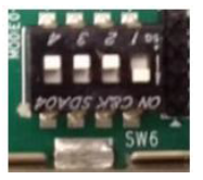
- Set the SW6 switches as shown in the below Figure. This configures the boot settings to boot from SD.
- Connect 12V Power to the ZCU106 6-Pin Molex connector.
- Connect one end of Display Port (DP) cable to board’s U129 connector and the other end to DP port of 4K monitor.
- Connect one end of HDMI cable to board’s P7 stacked HDMI connector (lower port) and another end to HDMI source in case of HDMI design.
- Connect one end of HDMI cable to board’s P7 stacked HDMI connector (upper port) and another end to HDMI monitor in case of HDMI design.
- Connect one end of SDI BNC cable to HD-BNC connector (J68) on board and another end to SDI source in case of SDI design.
- Connect one end of SDI BNC cable to HD-BNC connector (J10) on board and another end to SDI monitor/HDMI monitor with SDI to HDMI Converter in case of SDI design.
- For a USB storage device, connect USB hub along with the mouse. (Optional)
- For SATA storage device, connect SATA data cable to SATA 3.0 port. (Optional).
- For MIPI CSI-2, Insert the LI-IMX274MIPI-FMC image sensor daughter card into the FMC0 connector and set VADJ to 1.2V (See FMC VADJ Voltage Settings).
- Set up a terminal session between a PC COM port and the serial port on the evaluation board (See the Determine which COM to use to access the USB serial port on the ZCU106 board for more details).
- Copy the TRD images into the SD card and insert the SD card on the board.
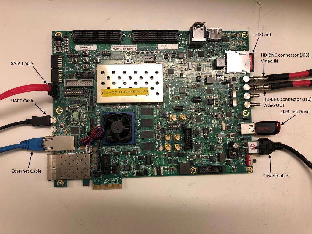
- The below images will show on how to connect interfaces on ZCU106 board.
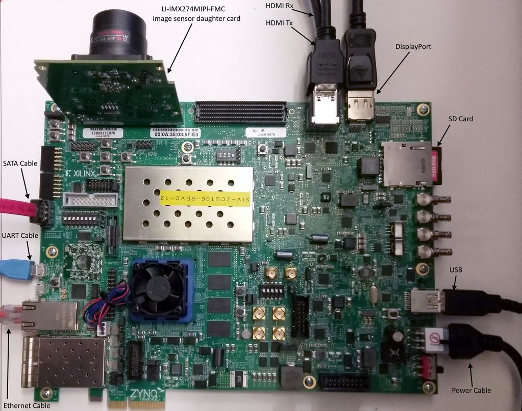
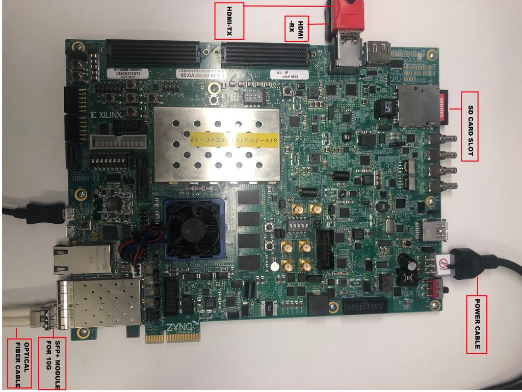
The figure shows the ZCU106 board connections for 10G HDMI-Rx and HDMI-Tx Streaming support
Determine which COM to use to access the USB serial port on the ZCU106 board.
Make sure that the ZCU106 board is powered on and a micro USB cable is connected between ZCU106 board and host PC. This ensures that the USB-to-serial bridge is enumerated by the PC host.
Open your computer's Control Panel by clicking on Start > Control Panel.
Note that the Start button is typically located in the lower left corner of the screen. Occasionally, it is in the upper left corner.
- Click Device Manager to open the Device Manager window. Note: You may be asked to confirm opening the Device Manager. If so, click YES.
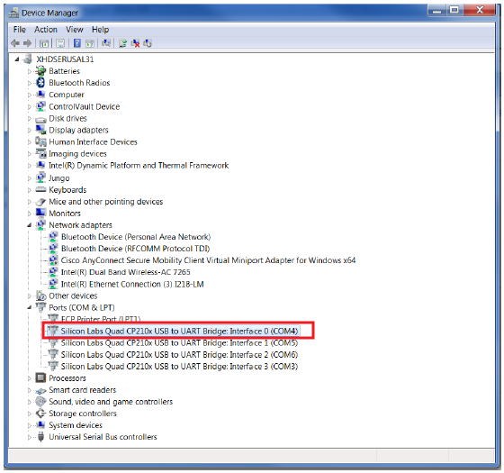
- Expand Ports (COM & LPT).
- Locate the Silicon Labs Quad CP210x USB to UART Bridge: Interface 0 (COM#).
- Note down the COM Port number for further steps.
- Close the Device Manager by clicking the red X in the upper right corner of the window.
Launch any Terminal application like Tera term to view the serial messages
- Launch Tera Term and open the COM port that is associated with Silicon Labs Quad CP210x USB to UART Bridge: Interface 0 of the USB-to-serial bridge.
- Set the COM port to 115200 Baud rate, 8, none, 1 –Set COM port.
- Power ON the board which has SD card. Switch ON SW1 to power the ZCU106 board.
It boots Linux on board and It takes about a minute for Linux to boot.
4 Design Files
4.1 Download the TRD
The TRD supports Rev C, Rev D, Rev E, Rev F and Rev 1.0 ZCU106 evaluation boards with Production silicon.
- Production Silicon: rdf0428-zcu106-vcu-trd-2018-3.zip
- Download the files at this location. https://www.xilinx.com/member/forms/download/design-license-xef.html?filename=rdf0428-zcu106-vcu-trd-2018-3.zip
4.2 TRD Directory Structure and Package Contents
The TRD package is released with the source code, Vivado project creation scripts, Petalinux BSP, and SD card image that enables the user to run the demonstration. It also includes the binaries necessary to configure and boot the ZCU106 board. Prior to running the steps mentioned in this wiki page, download the TRD package and extract its contents to a directory referred to as ‘TRD_HOME' which is the home directory.
Below figure depicts the directory structure and the hierarchy of the TRD package :
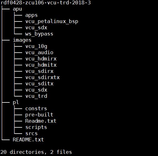
The top-level directory structure is described below:
- apu: It contains VCU Petalinux BSP, command line application and GUI application.
- apps: It contains vcu_apm_lib, vcu_video_lib, vcu_gst_lib, vcu_gst_app, and vcu_qt applications
- vcu_petalinux_bsp: It contains VCU TRD 2018.3 Petalinux BSP
- documentation: It contains test reports for all supported 2018.3 VCU TRD designs.
- images: It contains pre-built binaries i.e BOOT.BIN and image.ub, config files, vcu_gst_app, vcu_qt and necessary scripts for all supported 2018.3 designs.
- pl: This directory consists of subdirectories like - pre-built hdfs, Project creation scripts, Design constraints and the HDL source files required to create hardware project
5 Other Information
5.1 Known Issues
Refer to the individual wiki page links for known issues and limitation of that particular design.
6 Support
To obtain technical support for this reference design, go to the:
- Xilinx Answers Database to locate answers to known issues
- Xilinx Community Forums to ask questions or discuss technical details and issues. Please make sure to browse the existing topics first before filing a new topic. If you do file a new topic, make sure it is filed in the sub-forum that best describes your issue or question e.g. Embedded Linux for any Linux related questions. Please include "ZCU106 VCU TRD" and the release version in the topic name along with a brief summary of the issue.
© Copyright 2019 - 2022 Xilinx Inc. Privacy Policy