Table of Contents
1. Introduction
The design provided with this application note enable the use of multiple Ethernet ports and provide kernel-mode Linux device drivers. In addition, this document includes Ethernet performance measurement with checksum offload support enable.
This page discusses the following.
- Hardware and software design build steps for xapp1305 and xapp1306.
- Understanding & Bench-marking Ethernet performance for xapp1305 and xapp1306. Visit Performance page for Performance Numbers and Procedure to take performance numbers.
Please note: We fully verified and tested the designs with ZCU102 Rev1.1, production silicon(4.0) board. For 1G 1000BASE-X validation, Cisco GLC-T 1000BASE-X Ethernet to SFP Module is used(SN : AGM170623ZT).For 1G SGMII validation, Cisco GLC-T 1000BASE-T 100m RJ45 Ethernet to SFP Module is used(SN : CLS10310606).For 10G, Solarflare's SFN6322F Dual-Port 10GbE SFP+ Adapter is the NIC that has been used; and together with Avago afbr-709smz optical to Ethernet SFP+ module.
2. XAPP1305
XAPP1305 introduces:-
- PS-MIO (PS 1G), PS-EMIO-1000BASE-X(PS-PL),PS-EMIO SGMII(PS-PL),PL-1G-1000BASE-X, PL-1G-SGMII and PL-ETHERNET-10G -Ethernet designs
- Supports Vivado 2017.3
- Petalinux 2017.3 SDK
- macb driver support
- Supports Xilinx phy driver for 1000Base-X and SGMII
Six designs are described in this application note. The designs support Vivado IP Integrator tool flow.
2.1 Hardware Design
2.1.1 Building PS-MIO and PS-EMIO(1000BASE-X)
To rebuild the hardware design, execute the following (after setting up Vivado environment).
1. Open a Linux terminal or Vivado tcl shell in windows
2. Navigate to hardware/vivado/scripts/ps_emio_eth_1g for PS EMIO(1000BASE-X) Ethernet design
$ vivado -source ps_emio_eth_1g_top.tcl
( for PS_MIO design,navigate to hardware/vivado/scripts/ps_eth_1g and run 'vivado source ps_eth_1g_top.tcl' ,
rest of the steps remain the same)
This step creates a vivado project and opens the Vivado IDE with the design loaded (See tool snapshot below).
Relevant constraints file is also associated with the design.
NOTE : In this design "GEM3" is also enabled along with GEM0 in ZYNQ UltraScale+ GUI.
GEM3 is connected to on board ZCU102 TI RGMII PHY thorugh MIO and GEM0 is connected to PL through EMIO.

3. In the Flow Navigator Panel, click on 'Generate Bitstream' to implement the design and get a bitstream (see below Figure).

4. On completion of bitstream generation, open the implemented design (see below Figure).

5. Click on File --> Export --> Export Hardware to SDK (see below Figure)

6. Choose "Include bitstream" option, and click OK (see below Figure)

7. A hardware description file will be generated in <project_name>.sdk folder.
For xapp1305 software building, follow the steps mentioned in section 2.4.1 and for xapp1306, follow steps mentioned in section 3.
2.1.2 Building PL Ethernet(1G),PL Ethernet SGMII, PS EMIO Ethernet SGMII
To rebuild the hardware design, execute the following (after setting up Vivado environment).1. Open a Linux terminal or Vivado tcl shell in windows
2. Navigate to hardware/vivado/scripts/pl_eth_1g for PL Ethernet 1G (1000BASE-X) design
$ vivado -source pl_eth_1g_top.tcl
(For PL Ethernet SGMII, navigate to hardware/vivado/scripts/pl_eth_sgmii and run, 'vivado -source pl_eth_sgmii_top.tcl
For PS EMIO Ethernet SGMII, navigate to hardware/vivado/scripts/ps_emio_eth_sgmii and run, 'vivado -source ps_emio_eth_sgmii_top.tcl',
rest of the steps will remain the same)
This step creates the project and opens the Vivado IDE with the design loaded (See below Figure).
Relevant constraints file is also associated with the design.

3. In the Flow Navigator panel, click on 'Generate Bitstream' to implement the design and get a bitstream.

4. On completion of bitstream generation, open the implemented design (see below Figure).

5. Click on File --> Export --> Export Hardware to SDK (see below Figure)

6. Choose "Include bitstream" option, and click OK.

7. A hardware description file will be generated in <project_name>.sdk folder.
For xapp1305 software building, follow the steps mentioned in section 2.5.1 and for xapp1306, follow steps mentioned in section 3.
2.1.3 Building PL Ethernet(10G)
To rebuild the hardware design, execute the following (after setting up Vivado environment).- Open a Linux terminal or Vivado tcl shell in windows
- Navigate to hardware/vivado/scripts/pl_eth_10g for PL Ethernet 10G BASE-R design
$ vivado -source pl_eth_10g_top.tcl
This step creates the project and opens the Vivado IDE with the design loaded below Figure). Relevant constraints file is also associated with the design.

3. In the Flow Navigator panel, click on 'Generate Bitstream' to implement the design and get a bitstream.

4. On completion of bitstream generation, open the implemented design (see below Figure).

5. Click On File --> Export-->Export hardware to SDK ( see below Image)

6. Choose "Include bitstream" option, and click OK.

7. A hardware description file will be generated in <project_name>.sdk folder.
For software building, follow the steps mentioned in section 2.6.1.
2.2 PetaLinux Installation
Prerequisites
This section lists the requirements for the PetaLinux Tools Installation
- Download Petalinux 2017.3 SDK software from Xilinx website
- Refer to section 3.4 for PetaLinux installation instructions.
2.3 Directory structure
The xapp1305 is released with the source code, Xilinx Vivado and Petalinux projects and an SD card image that enables the user to run the demonstration.
It also includes the binaries necessary to configure and boot the Zynq UltraScale+ MPSoC board.
Download and unzip the XAPP package from xilinx website. Copy the content in to XAPP directory.
This DIrectory is refered as XAPP_HOME in rest of section.
2.3.1 xapp1305

2.3.2 xapp1306

PETALINUX BUILD PROCEDURE FOR 2019.1
Setup petalinux by sourcing it.
bash>source <path-to-petalinux-installer>/Petalinux-v2019.1_daily_latest/tool/petalinux-v2019.1-final/settings.sh
The package contains 6 designs namely-
ps_eth_1g, ps_emio_eth_1g and ps_emio_eth_sgmii, pl_ethernet_1g, pl_ethernet_sgmii and pl_ethernet_10g.
Create project from PetaLinux BSP
Use the following command on the console.
petalinux-create -t project -s <path-to-bsp>
bash> cd $XAPP_HOME/xapp1305-ps-pl-based-ethernet-solution/software

// for PS emio 1000BASE-X
bash> petalinux-create -t project -s bsps/xapp1305_ps_emio_ethernet_1g/ps_emio_eth_1g.bsp
// for PS emio SGMII
bash> petalinux-create -t project -s bsps/xapp1305_ps_emio_ethernet_sgmii/ps_emio_eth_sgmii.bsp
//for PS MIO
bash> petalinux-create -t project -s bsps/xapp1305_ps_ethernet_1g/ps_eth_1g.bsp
//for PL 1000BASE-X
bash> petalinux-create -t project -s bsps/xapp1305_pl_ethernet_1g/pl_eth_1g.bsp
//for PL SGMII
bash> petalinux-create -t project -s bsps/xapp1305_pl_ethernet_sgmii/pl_eth_sgmii.bsp
//for PL 10G
bash> petalinux-create -t project -s bsps/xapp1305_pl_ethernet_10g/pl_ethernet_10g.bsp
Configure PetaLinux
//for PS mio
bash> cd ps_eth_1g
// for PS emio 1000BASE-X
bash> cd ps_emio_eth_1g
// for PS emio SGMII
bash> cd ps_emio_eth_sgmii
//for PL 1000BASE-X
bash> cd pl_ethernet_1g
// for PL SGMII
bash> cd pl_ethernet_sgmii
//for PL 10G
bash> cd ps_ethernet_1g

bash> petalinux-config --oldconfig
NOTE: Above step may take a longer time depending on the network bandwidth.
Within petalinux-config menu, for all designs make sure that the machine name is set to "zcu102-rev1.0" as follows:-
In petalinux-config DTG Settings ---> (template) MACHINE_NAME, change the template to zcu102-rev1.0.
Configure the kernel
Check and enable the Xilinx PHY driver from kernel configuration.
bash> petalinux-config -c kernel
Device Drivers > Network device support > PHY Device support and infrastructure >
<*> Drivers for xilinx PHYs
Save the changes and exit.
For PL designs additionally, disable Xilinx AXI DMAS Engine
Device Drivers> DMA Engine Support> <> Xilinx AXI DMAS Engine
Save the changes and exit.
2.4.1.6 Build
Build images using PetaLinux.
bash> petalinux-build -v
2.4.1.7 Create Zynq-mp Boot image (BOOT.bin)
bash> cd images/linux

// for all designs
bash> petalinux-package --boot --fsbl=zynqmp_fsbl.elf --fpga=system.bit --u-boot
2.4.1.8 SD Images
SDcard Deployable binaries:-
a) BOOT.bin
b) image.ub
for PS emio
Copy BOOT.BIN and image.ub from $PETALINUX/ xapp1305_ps_emio_eth/images/linux to SD partition
For PS mio
Copy BOOT.BIN and image.ub from $PETALINUX/ xapp1305_ps_mio_eth/images/linux to SD partition
Note - You can either use bsps provided in the package or use --template option and petalinux-config command to chose default board configs that are close to your board designs.
Note: If you are building from the hdf generated from Vivado, then follow these steps:
petalinux-create --type project --template <PLATFORM> --name <PROJECT NAME>
petalinux-config --get-hw-description=<PATH-TO-HDF DIRECTORY>
//source petalinux
bash> source <path-to-petalinux-installer>/Petalinux-v2019.1_daily_latest/tool/petalinux-v2019.1-final/settings.sh
bash> petalinux-create --template zynqMP -t project -n <project_name>
bash> cd <project_name>
bash> petalinux-config --get-hw-description=<path_to_hdf>/hdf/
In petalinux-config DTG Settings ---> (template) MACHINE_NAME, change the template to zcu102-rev1.0.
Changes to system-user.dtsi
Modify the system-user.dtsi by navigating to the the file using 'vi project-spec/meta-user/recipes-bsp/device-tree/files/system-user.dtsi' ,
i) For the PS EMIO 1000BASE-X, and PS EMIO SGMII make the following modifications to system-user.dtsi,
/include/ "system-conf.dtsi"
/ {
};

&gem0 {
	phy-handle = <&phy9>;
	phy9: phy@9 {
		reg = <0x9>;
		xlnx,phy-type = <0x5>;
	    reset-gpios = <&gpio 78 0>;
	};
};

&i2c1 {
	pinctrl-names = "default", "gpio";
	pinctrl-0 = <&pinctrl_i2c1_default>;
	pinctrl-1 = <&pinctrl_i2c1_gpio>;
	scl-gpios = <&gpio 16 0>;
	sda-gpios = <&gpio 17 0>;

	/* FIXME PL i2c via PCA9306 - u45 */
	/* FIXME MSP430 - u41 - not detected */
	i2c-mux@74 { /* u34 */
		compatible = "nxp,pca9548";
		#address-cells = <1>;
		#size-cells = <0>;
		reg = <0x74>;
		i2c@0 { /* i2c mw 74 0 1 */
			#address-cells = <1>;
			#size-cells = <0>;
			reg = <0>;
			/*
			 * IIC_EEPROM 1kB memory which uses 256B blocks
			 * where every block has different address.
			 *    0 - 256B address 0x54
			 * 256B - 512B address 0x55
			 * 512B - 768B address 0x56
			 * 768B - 1024B address 0x57
			 */
			eeprom: eeprom@54 { /* u23 */
				compatible = "at,24c08";
				reg = <0x54>;
			};
		};
		i2c@1 { /* i2c mw 74 0 2 */
			#address-cells = <1>;
			#size-cells = <0>;
			reg = <1>;
			si5341: clock-generator1@36 { /* SI5341 - u69 */
				compatible = "si5341";
				reg = <0x36>;
			};

		};
		i2c@2 { /* i2c mw 74 0 4 */
			#address-cells = <1>;
			#size-cells = <0>;
			reg = <2>;
			si570_1: clock-generator2@5d { /* USER SI570 - u42 */
				#clock-cells = <0>;
				compatible = "silabs,si570";
				reg = <0x5d>;
				temperature-stability = <50>;
				factory-fout = <300000000>;
				clock-frequency = <300000000>;
			};
		};

		/delete-node/ i2c@3;

		i2c@4 { /* i2c mw 74 0 10 */
			#address-cells = <1>;
			#size-cells = <0>;
			reg = <4>;
			si5328: clock-generator4@69 {/* SI5328 - u20 */
				compatible = "silabs,si5328";
				reg = <0x69>;
				/*
				 * Chip has interrupt present connected to PL
				 * interrupt-parent = <&>;
				 * interrupts = <>;
				 */
			};
		};
		/* 5 - 7 unconnected */
	};
};
ii) For the PL 1G and PL SGMII, make the following modifications to system-user.dtsi,
/include/ "system-conf.dtsi"
/ {
};
&gem0 {
	phy-handle = <&phy9>;
	phy9: phy@9 {
		reg = <0x9>;
		xlnx,phy-type = <0x4>;
	};
};

&i2c1 {
	pinctrl-names = "default", "gpio";
	pinctrl-0 = <&pinctrl_i2c1_default>;
	pinctrl-1 = <&pinctrl_i2c1_gpio>;
	scl-gpios = <&gpio 16 0>;
	sda-gpios = <&gpio 17 0>;

	/* FIXME PL i2c via PCA9306 - u45 */
	/* FIXME MSP430 - u41 - not detected */
	i2c-mux@74 { /* u34 */
		compatible = "nxp,pca9548";
		#address-cells = <1>;
		#size-cells = <0>;
		reg = <0x74>;
		i2c@0 { /* i2c mw 74 0 1 */
			#address-cells = <1>;
			#size-cells = <0>;
			reg = <0>;
			/*
			 * IIC_EEPROM 1kB memory which uses 256B blocks
			 * where every block has different address.
			 *    0 - 256B address 0x54
			 * 256B - 512B address 0x55
			 * 512B - 768B address 0x56
			 * 768B - 1024B address 0x57
			 */
			eeprom: eeprom@54 { /* u23 */
				compatible = "at,24c08";
				reg = <0x54>;
			};
		};
		i2c@1 { /* i2c mw 74 0 2 */
			#address-cells = <1>;
			#size-cells = <0>;
			reg = <1>;
			si5341: clock-generator1@36 { /* SI5341 - u69 */
				compatible = "si5341";
				reg = <0x36>;
			};

		};
		i2c@2 { /* i2c mw 74 0 4 */
			#address-cells = <1>;
			#size-cells = <0>;
			reg = <2>;
			si570_1: clock-generator2@5d { /* USER SI570 - u42 */
				#clock-cells = <0>;
				compatible = "silabs,si570";
				reg = <0x5d>;
				temperature-stability = <50>;
				factory-fout = <300000000>;
				clock-frequency = <300000000>;
			};
		};

		/delete-node/ i2c@3;

		i2c@4 { /* i2c mw 74 0 10 */
			#address-cells = <1>;
			#size-cells = <0>;
			reg = <4>;
			si5328: clock-generator4@69 {/* SI5328 - u20 */
				compatible = "silabs,si5328";
				reg = <0x69>;
				/*
				 * Chip has interrupt present connected to PL
				 * interrupt-parent = <&>;
				 * interrupts = <>;
				 */
			};
		};
		/* 5 - 7 unconnected */
	};
};
For PL 10G make the following modifications to system-user.dtsi.
/include/ "system-conf.dtsi"
/ {
};

&i2c1 {
	pinctrl-names = "default", "gpio";
	pinctrl-0 = <&pinctrl_i2c1_default>;
	pinctrl-1 = <&pinctrl_i2c1_gpio>;
	scl-gpios = <&gpio 16 0>;
	sda-gpios = <&gpio 17 0>;

	/* FIXME PL i2c via PCA9306 - u45 */
	/* FIXME MSP430 - u41 - not detected */
	i2c-mux@74 { /* u34 */
		compatible = "nxp,pca9548";
		#address-cells = <1>;
		#size-cells = <0>;
		reg = <0x74>;
		i2c@0 { /* i2c mw 74 0 1 */
			#address-cells = <1>;
			#size-cells = <0>;
			reg = <0>;
			/*
			 * IIC_EEPROM 1kB memory which uses 256B blocks
			 * where every block has different address.
			 *    0 - 256B address 0x54
			 * 256B - 512B address 0x55
			 * 512B - 768B address 0x56
			 * 768B - 1024B address 0x57
			 */
			eeprom: eeprom@54 { /* u23 */
				compatible = "at,24c08";
				reg = <0x54>;
			};
		};
		i2c@1 { /* i2c mw 74 0 2 */
			#address-cells = <1>;
			#size-cells = <0>;
			reg = <1>;
			si5341: clock-generator1@36 { /* SI5341 - u69 */
				compatible = "si5341";
				reg = <0x36>;
			};

		};
		i2c@2 { /* i2c mw 74 0 4 */
			#address-cells = <1>;
			#size-cells = <0>;
			reg = <2>;
			si570_1: clock-generator2@5d { /* USER SI570 - u42 */
				#clock-cells = <0>;
				compatible = "silabs,si570";
				reg = <0x5d>;
				temperature-stability = <50>;
				factory-fout = <300000000>;
				clock-frequency = <300000000>;
			};
		};

		/delete-node/ i2c@3;

		i2c@4 { /* i2c mw 74 0 10 */
			#address-cells = <1>;
			#size-cells = <0>;
			reg = <4>;
			si5328: clock-generator4@69 {/* SI5328 - u20 */
				compatible = "silabs,si5328";
				reg = <0x69>;
				/*
				 * Chip has interrupt present connected to PL
				 * interrupt-parent = <&>;
				 * interrupts = <>;
				 */
			};
		};
		/* 5 - 7 unconnected */
	};
};
Patches to apply
AR 71295
Please note, there is a patch needed for PS EMIO 1G and PS EMIO SGMII to make sure the si570 frequency is correctly set.
This patch is provided at <Release folder>->softwares->patches->0001-fsbl-si570-clk-config-on-A53.patch
Navigate to project-spec->meta-user->recipes-bsp.Create a folder'fsbl' → 'files' and add this patch. Also, create a file called fsbl_%.bbappendwithin"fsbl"folder and add the following to it.
do_configure_prepend() {
    if [ -d "${S}/patches" ]; then
       rm -rf ${S}/patches
    fi

    if [ -d "${S}/.pc" ]; then
       rm -rf ${S}/.pc
    fi
}

FILESEXTRAPATHS_prepend := "${THISDIR}/files:"

#Add debug for FSBL(optional)
XSCTH_BUILD_DEBUG = "1"

#Enable appropriate FSBL debug flags
YAML_COMPILER_FLAGS_append = " -DXPS_BOARD_ZCU102"

# Note: This is not required if you are using Yocto
EXTERNALXSCTSRC = ""
EXTERNALXSCTSRC_BUILD = ""
SRC_URI_append = "\
		    file://0001-fsbl-si570-clk-config-on-A53.patch \
			"
More details can be found in the following AR:
https://www.xilinx.com/support/answers/71295.html
for PS EMIO 1G and PS EMIO SGMII
Navigate to project-spec->meta-user->recipes-kernel->linux→linux_xlnx. Add the two patches, available here AR-72806.
project-spec->meta-user->recipes-kernel->linux→linux_xlnx_%.bbappend. Add the two patches.
Then, proceed with kernel configuration and build and package the same way as mentioned above.
2019.1 XAPP1305 PS and PL-Based 1G/10G Ethernet Solution - Performance testing results
| Design | PING test | MTU 1500 | MTU 8192 | ||||||
| TCP TX | TCP RX | UDP TX | UDP RX | TCP TX | TCP RX | UDP TX | UDP RX | ||
| pl_ethernet_10g | Working | 1.26G | 1.54G | 9.60G | 1.82G | 3.44G | 2.8G | 8.06G | 1.66G |
| ps_emio_eth_sgmii | Working | 866.69 | 941.5 | 954.23 | 992.16 | 986.08 | 989.11 | 988.53 | 992.07 |
| ps_emio_eth_1g | Working | 931.61 | 941.51 | 954.22 | 961.71 | 986.08 | 968.81 | 988.53 | 992.12 |
| pl_ethernet_sgmii | Working | 933.35 | 941.49 | 954.23 | 961.81 | 986.07 | 989.11 | 988.54 | 745.7 |
| pl_ethernet_1g | Working | 925.89 | 941.39 | 954.27 | 961.8 | 986.03 | 977.44 | 988.54 | 737.21 |
| pl_10g Back to Back | Working | 1.35G | 1.41G | 1.85G | 1.84G | 2.74G | 2.77G | 1.67G | 1.66G |
| ps_ethernet_1g | Working | 924.63 | 941.32 | 954.23 | 834.39 | 986.08 | 988.92 | 988.54 | 991.95 |
PETALINUX BUILD PROCEDURE FOR 2018.3
Setup petalinux by sourcing it.
bash>source <path-to-petalinux-installer>/Petalinux-v2018.3/petalinux-v2018.3-final/settings.csh
The package contains 6 designs namely-
ps_eth_1g, ps_emio_eth_1g and ps_emio_eth_sgmii, pl_ethernet_1g, pl_ethernet_sgmii and pl_ethernet_10g.
Create project from PetaLinux BSP
Use the following command on the console.
petalinux-create -t project -s <path-to-bsp>
bash> cd $XAPP_HOME/xapp1305-ps-pl-based-ethernet-solution/software

// for PS emio 1000BASE-X
bash> petalinux-create -t project -s bsps/xapp1305_ps_emio_ethernet_1g/ps_emio_eth_1g.bsp
// for PS emio SGMII
bash> petalinux-create -t project -s bsps/xapp1305_ps_emio_ethernet_sgmii/ps_emio_eth_sgmii.bsp
//for PS MIO
bash> petalinux-create -t project -s bsps/xapp1305_ps_ethernet_1g/ps_eth_1g.bsp
//for PL 1000BASE-X
bash> petalinux-create -t project -s bsps/xapp1305_pl_ethernet_1g/pl_eth_1g.bsp
//for PL SGMII
bash> petalinux-create -t project -s bsps/xapp1305_pl_ethernet_sgmii/pl_eth_sgmii.bsp
//for PL 10G
bash> petalinux-create -t project -s bsps/xapp1305_pl_ethernet_10g/pl_ethernet_10g.bsp
Configure PetaLinux
//for PS mio
bash> cd ps_eth_1g
// for PS emio 1000BASE-X
bash> cd ps_emio_eth_1g
// for PS emio SGMII
bash> cd ps_emio_eth_sgmii
//for PL 1000BASE-X
bash> cd pl_ethernet_1g
// for PL SGMII
bash> cd pl_ethernet_sgmii
//for PL 10G
bash> cd ps_ethernet_1g

bash> petalinux-config --oldconfig
NOTE: Above step may take a longer time depending on the network bandwidth.
Within petalinux-config menu, for all designs make sure that the machine name is set to "zcu102-rev1.0" as follows:-
In petalinux-config DTG Settings ---> (template) MACHINE_NAME, change the template to zcu102-rev1.0.
Configure the kernel
Check and enable the Xilinx PHY driver from kernel configuration.
bash> petalinux-config -c kernel
Device Drivers > Network device support > PHY Device support and infrastructure >
<*> Drivers for xilinx PHYs
Save the changes and exit.
For PL designs additionally, disable Xilinx AXI DMAS Engine
Device Drivers> DMA Engine Support> <> Xilinx AXI DMAS Engine
Save the changes and exit.
2.4.1.6 Build
Build images using PetaLinux.
bash> petalinux-build -v
2.4.1.7 Create Zynq-mp Boot image (BOOT.bin)
bash> cd images/linux

// for all designs
bash> petalinux-package --boot --fsbl=zynqmp_fsbl.elf --fpga=system.bit --u-boot
2.4.1.8 SD Images
SDcard Deployable binaries:-
a) BOOT.bin
b) image.ub
for PS emio
Copy BOOT.BIN and image.ub from $PETALINUX/ xapp1305_ps_emio_eth/images/linux to SD partition
For PS mio
Copy BOOT.BIN and image.ub from $PETALINUX/ xapp1305_ps_mio_eth/images/linux to SD partition
Note - You can either use bsps provided in the package or use --template option and petalinux-config command to chose default board configs that are close to your board designs.
Note: If you are building from the hdf generated from Vivado, then follow these steps:
petalinux-create --type project --template <PLATFORM> --name <PROJECT NAME>
petalinux-config --get-hw-description=<PATH-TO-HDF DIRECTORY>
//source petalinux
bash> source <path-to-petalinux-installer>/Petalinux-v2018.3/petalinux-v2018.3-final/settings.csh
bash> petalinux-create --template zynqMP -t project -n <project_name>
bash> cd <project_name>
bash> petalinux-config --get-hw-description=<path_to_hdf>/hdf/
In petalinux-config DTG Settings ---> (template) MACHINE_NAME, change the template to zcu102-rev1.0.
Changes to system-user.dtsi
Modify the system-user.dtsi by navigating to the the file using 'vi project-spec/meta-user/recipes-bsp/device-tree/files/system-user.dtsi' ,
i) For the PS EMIO 1000BASE-X, and PL 1G make the following modifications to system-user.dtsi,
/include/ "system-conf.dtsi"
/ {
};

&gem0 {
	phy-handle = <&phy9>;
	phy9: phy@9 {
		reg = <0x9>;
		xlnx,phy-type = <0x5>;
	};
};

&i2c1 {
	pinctrl-names = "default", "gpio";
	pinctrl-0 = <&pinctrl_i2c1_default>;
	pinctrl-1 = <&pinctrl_i2c1_gpio>;
	scl-gpios = <&gpio 16 0>;
	sda-gpios = <&gpio 17 0>;

	/* FIXME PL i2c via PCA9306 - u45 */
	/* FIXME MSP430 - u41 - not detected */
	i2c-mux@74 { /* u34 */
		compatible = "nxp,pca9548";
		#address-cells = <1>;
		#size-cells = <0>;
		reg = <0x74>;
		i2c@0 { /* i2c mw 74 0 1 */
			#address-cells = <1>;
			#size-cells = <0>;
			reg = <0>;
			/*
			 * IIC_EEPROM 1kB memory which uses 256B blocks
			 * where every block has different address.
			 *    0 - 256B address 0x54
			 * 256B - 512B address 0x55
			 * 512B - 768B address 0x56
			 * 768B - 1024B address 0x57
			 */
			eeprom: eeprom@54 { /* u23 */
				compatible = "at,24c08";
				reg = <0x54>;
			};
		};
		i2c@1 { /* i2c mw 74 0 2 */
			#address-cells = <1>;
			#size-cells = <0>;
			reg = <1>;
			si5341: clock-generator1@36 { /* SI5341 - u69 */
				compatible = "si5341";
				reg = <0x36>;
			};

		};
		i2c@2 { /* i2c mw 74 0 4 */
			#address-cells = <1>;
			#size-cells = <0>;
			reg = <2>;
			si570_1: clock-generator2@5d { /* USER SI570 - u42 */
				#clock-cells = <0>;
				compatible = "silabs,si570";
				reg = <0x5d>;
				temperature-stability = <50>;
				factory-fout = <300000000>;
				clock-frequency = <300000000>;
			};
		};

		/delete-node/ i2c@3;

		i2c@4 { /* i2c mw 74 0 10 */
			#address-cells = <1>;
			#size-cells = <0>;
			reg = <4>;
			si5328: clock-generator4@69 {/* SI5328 - u20 */
				compatible = "silabs,si5328";
				reg = <0x69>;
				/*
				 * Chip has interrupt present connected to PL
				 * interrupt-parent = <&>;
				 * interrupts = <>;
				 */
			};
		};
		/* 5 - 7 unconnected */
	};
};
ii) For the PS EMIO SGMII and PL SGMII, make the following modifications to system-user.dtsi,
/include/ "system-conf.dtsi"
/ {
};
&gem0 {
	phy-handle = <&phy9>;
	phy9: phy@9 {
		reg = <0x9>;
		xlnx,phy-type = <0x4>;
	};
};

&i2c1 {
	pinctrl-names = "default", "gpio";
	pinctrl-0 = <&pinctrl_i2c1_default>;
	pinctrl-1 = <&pinctrl_i2c1_gpio>;
	scl-gpios = <&gpio 16 0>;
	sda-gpios = <&gpio 17 0>;

	/* FIXME PL i2c via PCA9306 - u45 */
	/* FIXME MSP430 - u41 - not detected */
	i2c-mux@74 { /* u34 */
		compatible = "nxp,pca9548";
		#address-cells = <1>;
		#size-cells = <0>;
		reg = <0x74>;
		i2c@0 { /* i2c mw 74 0 1 */
			#address-cells = <1>;
			#size-cells = <0>;
			reg = <0>;
			/*
			 * IIC_EEPROM 1kB memory which uses 256B blocks
			 * where every block has different address.
			 *    0 - 256B address 0x54
			 * 256B - 512B address 0x55
			 * 512B - 768B address 0x56
			 * 768B - 1024B address 0x57
			 */
			eeprom: eeprom@54 { /* u23 */
				compatible = "at,24c08";
				reg = <0x54>;
			};
		};
		i2c@1 { /* i2c mw 74 0 2 */
			#address-cells = <1>;
			#size-cells = <0>;
			reg = <1>;
			si5341: clock-generator1@36 { /* SI5341 - u69 */
				compatible = "si5341";
				reg = <0x36>;
			};

		};
		i2c@2 { /* i2c mw 74 0 4 */
			#address-cells = <1>;
			#size-cells = <0>;
			reg = <2>;
			si570_1: clock-generator2@5d { /* USER SI570 - u42 */
				#clock-cells = <0>;
				compatible = "silabs,si570";
				reg = <0x5d>;
				temperature-stability = <50>;
				factory-fout = <300000000>;
				clock-frequency = <300000000>;
			};
		};

		/delete-node/ i2c@3;

		i2c@4 { /* i2c mw 74 0 10 */
			#address-cells = <1>;
			#size-cells = <0>;
			reg = <4>;
			si5328: clock-generator4@69 {/* SI5328 - u20 */
				compatible = "silabs,si5328";
				reg = <0x69>;
				/*
				 * Chip has interrupt present connected to PL
				 * interrupt-parent = <&>;
				 * interrupts = <>;
				 */
			};
		};
		/* 5 - 7 unconnected */
	};
};
For PL 10G make the following modifications to system-user.dtsi.
/include/ "system-conf.dtsi"
/ {
};

&i2c1 {
	pinctrl-names = "default", "gpio";
	pinctrl-0 = <&pinctrl_i2c1_default>;
	pinctrl-1 = <&pinctrl_i2c1_gpio>;
	scl-gpios = <&gpio 16 0>;
	sda-gpios = <&gpio 17 0>;

	/* FIXME PL i2c via PCA9306 - u45 */
	/* FIXME MSP430 - u41 - not detected */
	i2c-mux@74 { /* u34 */
		compatible = "nxp,pca9548";
		#address-cells = <1>;
		#size-cells = <0>;
		reg = <0x74>;
		i2c@0 { /* i2c mw 74 0 1 */
			#address-cells = <1>;
			#size-cells = <0>;
			reg = <0>;
			/*
			 * IIC_EEPROM 1kB memory which uses 256B blocks
			 * where every block has different address.
			 *    0 - 256B address 0x54
			 * 256B - 512B address 0x55
			 * 512B - 768B address 0x56
			 * 768B - 1024B address 0x57
			 */
			eeprom: eeprom@54 { /* u23 */
				compatible = "at,24c08";
				reg = <0x54>;
			};
		};
		i2c@1 { /* i2c mw 74 0 2 */
			#address-cells = <1>;
			#size-cells = <0>;
			reg = <1>;
			si5341: clock-generator1@36 { /* SI5341 - u69 */
				compatible = "si5341";
				reg = <0x36>;
			};

		};
		i2c@2 { /* i2c mw 74 0 4 */
			#address-cells = <1>;
			#size-cells = <0>;
			reg = <2>;
			si570_1: clock-generator2@5d { /* USER SI570 - u42 */
				#clock-cells = <0>;
				compatible = "silabs,si570";
				reg = <0x5d>;
				temperature-stability = <50>;
				factory-fout = <300000000>;
				clock-frequency = <300000000>;
			};
		};

		/delete-node/ i2c@3;

		i2c@4 { /* i2c mw 74 0 10 */
			#address-cells = <1>;
			#size-cells = <0>;
			reg = <4>;
			si5328: clock-generator4@69 {/* SI5328 - u20 */
				compatible = "silabs,si5328";
				reg = <0x69>;
				/*
				 * Chip has interrupt present connected to PL
				 * interrupt-parent = <&>;
				 * interrupts = <>;
				 */
			};
		};
		/* 5 - 7 unconnected */
	};
};
Patches to apply
AR 71295
Please note, there is a patch needed for PS EMIO 1G and PS EMIO SGMII to make sure the si570 frequency is correctly set.
This patch is provided at <Release folder>->softwares->patches->0001-fsbl-si570-clk-config-on-A53.patch
Navigate to project-spec->meta-user->recipes-bsp. Create a folder 'fsbl' → 'files' and add this patch. Also, create a file called fsbl_%.bbappend within "fsbl" folder and add the following to it.
do_configure_prepend() {
    if [ -d "${S}/patches" ]; then
       rm -rf ${S}/patches
    fi

    if [ -d "${S}/.pc" ]; then
       rm -rf ${S}/.pc
    fi
}

FILESEXTRAPATHS_prepend := "${THISDIR}/files:"

#Add debug for FSBL(optional)
XSCTH_BUILD_DEBUG = "1"

#Enable appropriate FSBL debug flags
YAML_COMPILER_FLAGS_append = " -DXPS_BOARD_ZCU102"

# Note: This is not required if you are using Yocto
EXTERNALXSCTSRC = ""
EXTERNALXSCTSRC_BUILD = ""
SRC_URI_append = "\
		    file://0001-fsbl-si570-clk-config-on-A53.patch \
			"
More details can be found in the following AR:
https://www.xilinx.com/support/answers/71295.html
AR 72113
Newer DIMMs in ZCU102 (>0432055-05) boards are in a small number of cases failing in boot with no FSBL messages output.The issue was due to DDR-PHY training happening twice for the new DIMM (once in the psu_init code and once in the DDR SPD code). Please visit AR 72113 to find more information and workaround patch.
To download the patch click Patch.
After downloading the patch copy it to project-spec->meta-user->recipes-bsp. Create a folder 'fsbl' → 'files' and add this patch. Also, create a file called fsbl_%.bbappend within "fsbl" folder and add the following to it.
For the PL 1G, PL SGMII, PL 10G, make the following modifications to system-user.dtsi,
# Patch for FSBL

# Note: do_configure_prepend task section is required only for 2017.1 release

# Refer https://github.com/Xilinx/meta-xilinx-tools/blob/rel-v2017.2/classes/xsctbase.bbclass#L29-L35


do_configure_prepend() {

    if [ -d "${S}/patches" ]; then

       rm -rf ${S}/patches

    fi


    if [ -d "${S}/.pc" ]; then

       rm -rf ${S}/.pc

    fi

}


SRC_URI_append = "\
        file://0001-FSBL.patch \
		"


FILESEXTRAPATHS_prepend := "${THISDIR}/files:"


#Add debug for FSBL(optional)

XSCTH_BUILD_DEBUG = "1"


#Enable appropriate FSBL debug flags

YAML_COMPILER_FLAGS_append = " -DXPS_BOARD_ZCU102"


# Note: This is not required if you are using Yocto

# CAUTION!: EXTERNALXSCTSRC and EXTERNALXSCTSRC_BUILD is required only for 2018.2 and below petalinux releases

EXTERNALXSCTSRC = ""

EXTERNALXSCTSRC_BUILD = ""
For the PS EMIO 1G, PS EMIO SGMII,make the following modifications to system-user.dtsi,
# Patch for FSBL
# Note: do_configure_prepend task section is required only for 2017.1 release
# Refer https://github.com/Xilinx/meta-xilinx-tools/blob/rel-v2017.2/classes/xsctbase.bbclass#L29-L35

do_configure_prepend() {
    if [ -d "${S}/patches" ]; then
       rm -rf ${S}/patches
    fi

    if [ -d "${S}/.pc" ]; then
       rm -rf ${S}/.pc
    fi
}

SRC_URI_append = " \
             file://0001-fsbl-si570-clk-config-on-A53.patch \
	         file://0001-FSBL.patch \
	         "
FILESEXTRAPATHS_prepend := "${THISDIR}/files:"

#Add debug for FSBL(optional)
XSCTH_BUILD_DEBUG = "1"

#Enable appropriate FSBL debug flags
YAML_COMPILER_FLAGS_append = " -DXPS_BOARD_ZCU102"

# Note: This is not required if you are using Yocto
EXTERNALXSCTSRC = ""
EXTERNALXSCTSRC_BUILD = ""
Then, proceed with kernel configuration and build and package the same way as mentioned above.
2018.3 XAPP1305 PS and PL-Based 1G/10G Ethernet Solution - Performance testing results
| Design | PING test | MTU 1500 | MTU 8192 | ||||||
|---|---|---|---|---|---|---|---|---|---|
TCP TX | TCP RX | UDP TX | UDP RX | TCP TX | TCP RX | UDP TX | UDP RX | ||
| ps_ethernet_1g | Working | 941.34 | 934.36 | 961.43 | 954.39 | 988.95 | 986.21 | 991.96 | 988.70 |
| ps_emio_eth_sgmii | Working | 941.55 | 933.84 | 961.67 | 954.34 | 989.06 | 986.30 | 992.09 | 988.64 |
| ps_emio_eth_1g | Working | 941.33 | 934.08 | 961.67 | 954.34 | 988.81 | 986.30 |
| 988.69 |
| pl_ethernet_sgmii | Working | 941.25 | 931.04 | 961.67 | 954.35 | 989.14 | 986.26 | 760.64(without -m) 985.19 (with -m) | 988.65 |
| pl_ethernet_1g | Working | 941.26 | 934.40 | 961.67 | 954.35 | 989.14 | 986.27 | 761.10 (without -m) 985.21 (with -m) | 988.65 |
| pl_10g Back to Back | Working | 1.1G | 1.30G | 1.588G | 1.58G | 1.95G | 2.84G | 2.28G | 2.27G |
PETALINUX BUILD PROCEDURE FOR 2017.3
Note: If you are building from the hdf generated from Vivado, then follow these steps:
bash> source <path-to-petalinux-installer>/Petalinux-v2017.3/petalinux-v2017.3-final/settings.sh
bash> petalinux-create --template zynqMP -t project -n <project_name>
bash> cd <project_name>
bash> petalinux-config --get-hw-description=<path_to_hdf>/hdf/

Then, you can proceed with the kernel configuration as well as dtsi additions as mentioned for each design specifically.
PS MIO and PS EMIO(1000BASE-X and SGMII) Ethernet
PS MIO and PS EMIO Ethernet BSP(1000BASE-X and SGMII) installation
PS-Ethernet/PS+PL Ethernet project provides installable BSP, which includes all necessary design sources, configuration files, tested hardware images and software images.
Create PS MIO and PS EMIO Ethernet project from PetaLinux BSP
Run petalinux-create command on the console
petalinux-create -t project -s <path-to-bsp>
bash> cd $XAPP_HOME/xapp1305-ps-pl-based-ethernet-solution/software

// for PS emio 1000BASE-X
bash> petalinux-create -t project -s bsps/xapp1305_ps_emio_ethernet_1g/ps_emio_eth_1g.bsp
// for PS emio SGMII
bash> petalinux-create -t project -s bsps/xapp1305_ps_emio_ethernet_sgmii/ps_emio_eth_sgmii.bsp(for SGMII)

//for PS MIO
bash> petalinux-create -t project -s bsps/xapp1305_ps_ethernet_1g/ps_eth_1g.bsp
2.4.1.2 Configure PetaLinux
// for PS emio 1000BASE-X
bash> cd ps_emio_eth_1g
// for PS emio SGMII
bash> cd ps_emio_eth_sgmii

//for PS mio
bash> cd ps_eth_1g

bash> petalinux-config
NOTE: Above step may take a longer time depending on the network bandwidth.
Configure the kernel
Check and enable the Xilinx PHY driver from kernel configuration.
bash> petalinux-config -c kernel
Device Drivers > Network device support > PHY Device support and infrastructure >
<*> Drivers for xilinx PHYs
Save the changes and exit.
Edit device for PS EMIO
Follow below process for PS-EMIO only.
Modifications to system-user.dtsi
Modify the system-user.dtsi by navigating to the the file using 'vi project-spec/meta-user/recipes-bsp/device-tree/files/system-user.dtsi' ,
i) For the PS EMIO 1000BASE-X, make the following modifications to system-user.dtsi,
/include/ "system-conf.dtsi"
/ {
};
&gem0 {
phy-handle = <&phy9>;
phy9: phy@9 {
reg = <0x9>;
xlnx,phy-type = <0x5>;
};
};
&i2c1 {
status = "okay";
clock-frequency = <400000>;
i2cswitch@74 { /* u34 */
compatible = "nxp,pca9548";
#address-cells = <1>;
#size-cells = <0>;
reg = <0x74>;
/delete-node/i2c@3;
};
};
ii) For the PS EMIO SGMII, make the following modifications to system-user.dtsi,
/include/ "system-conf.dtsi"
/ {
};
&gem0 {
phy-handle = <&phy9>;
phy9: phy@9 {
reg = <0x9>;
xlnx,phy-type = <0x4>;
};
};
&i2c1 {
status = "okay";
clock-frequency = <400000>;
i2cswitch@74 { /* u34 */
compatible = "nxp,pca9548";
#address-cells = <1>;
#size-cells = <0>;
reg = <0x74>;
/delete-node/i2c@3;
};
};
Please note, there is a patch needed for PS EMIO 1G and PS EMIO SGMII to make sure the si570 frequency is correctly set.
More details can be found in the following AR:
https://www.xilinx.com/support/answers/71295.html
2.4.1.6 Build
Build images using PetaLinux.
bash> petalinux-build -v
2.4.1.7 Create Zynq-mp Boot image (BOOT.bin)
bash> cd images/linux

// for PS emio 1000base-x
bash> petalinux-package --boot --fsbl=zynqmp_fsbl.elf --fpga=ps_emio_eth_1g_wrapper.bit --u-boot
// for PS emio SGMII
bash> petalinux-package --boot --fsbl=zynqmp_fsbl.elf --fpga=ps_emio_eth_sgmii_wrapper.bit --u-boot
//for PS mio
bash> petalinux-package --boot --fsbl=zynqmp_fsbl.elf --fpga=ps_emio_eth_1g_wrapper.bit --u-boot
2.4.1.8 SD Images
SDcard Deployable binaries:-
a) BOOT.bin
b) image.ub
for PS emio
Copy BOOT.BIN and image.ub from $PETALINUX/ xapp1305_ps_emio_eth/images/linux to SD partition
For PS mio
Copy BOOT.BIN and image.ub from $PETALINUX/ xapp1305_ps_mio_eth/images/linux to SD partition
2.5 PL Ethernet 1G(1000BASE-X and SGMII)
PL Ethernet project provides installable BSP, which includes all necessary design sources, configuration files, tested hardware images and software images.
The design supports with the auto-negotiation for speeds of 10/100/1000 Mbps and full duplex mode.
NOTE : Check-sum offload in enabled in the default configuration.
2.5.1 PL Ethernet BSP installation for 1000Base-X and SGMII
PL Ethernet project provides installable BSP which includes all necessary design sources and configuration files, including pre-built and tested hardware and software images, ready for download to your board.
2.5.1.1 Create PL Ethernet project from petalinux installable BSP
Run petalinux-create command on the command console:
petalinux-create -t project -s <path-to-bsp>
bash> cd $XAPP_HOME/xapp1305-ps-pl-based-ethernet-solution/software
bash> petalinux-create -t project -s bsps/xapp1305_pl_ethernet_1g/pl_eth_1g.bsp
bash> petalinux-create -t project -s bsps/xapp1305_pl_ethernet_sgmii/pl_eth_sgmii.bsp(for SGMII)
2.5.1.2 Configure petalinux
bash> cd pl_ethernet_1g
bash> cd pl_ethernet_sgmii(for SGMII)
bash> petalinux-config
NOTE: Above step may take a longer time depending on the network bandwidth.
2.5.1.3 Configure the kernel
bash> petalinux-config -c kernel
Enable the Xilinx PHY driver and Disable the AXI DMA driver
Device Drivers> Network device support > PHY Device support and infrastructure >
<*> Drivers for xilinx PHYs
Device Drivers> DMA Engine Support > <> Xilinx AXI DMAS Engine
Save the changes and exit.
2.5.1.4 Build
Build all images using PetaLinux.
bash> petalinux-build -v
2.5.1.5 Create Zynq-mp Boot image (BOOT.bin)
bash> cd images/linux
bash> petalinux-package --boot --fsbl=zynqmp_fsbl.elf --fpga=pl_eth_1g_wrapper.bit --u-boot
bash> petalinux-package --boot --fsbl=zynqmp_fsbl.elf --fpga=pl_eth_sgmii_wrapper.bit --u-boot
2.5.1.6 SD Images
SD Deployable binaries:-
a) BOOT.bin
b) image.ub
Copy BOOT.BIN and image.ub from $PETALINUX/ xapp1305_pl_eth/images/linux to SD partition.
2.6 PL Ethernet BSP installation (10G)
2.6.1 PL Ethernet 10G BASE-R BSP installation
2.6.1.1 Create PL Ethernet project from petalinux installable BSP
Run petalinux-create command on the command console:
petalinux-create -t project -s <path-to-bsp>
bash> cd $XAPP_HOME/xapp1305-ps-pl-based-ethernet-solution/software
bash> petalinux-create -t project -s bsps/xapp1305_pl_ethernet_10g/pl_ethernet_10g.bsp
2.6.1.2 Configure petalinux
bash> cd pl_ethernet_10g
bash> petalinux-config
NOTE: Above step may take a longer time depending on the network bandwidth.
Zynq UltraScale+ MPSoC
2.6.1.3 Configure the kernel
bash> petalinux-config -c kernel
Enable the Xilinx PHY driver and Disable the AXI DMA driver
Device Drivers> Network device support > PHY Device support and infrastructure >
<*> Drivers for xilinx PHYs
Device Drivers> DMA Engine Support> <> Xilinx AXI DMAS Engine
Save the changes and exit.
2.6.1.4 Applying the patch if necessary
Place the patch "0001-Remove-the-axistream-related-properties.patch" , at project-spec/meta-user/recipes-bsp/device-tree/files/.
The patch should be applied to <plnx-proj-root>/project-spec/meta-user/recipes-bsp/device-tree/device-tree-generation_%.bbappend, add it in the file as follows,
SRC_URI_append ="\
file:system-user.dtsi \
file:0001-Remove-the-axistream-related-properties.patch \
"
FILESEXTRAPATHS_prepend := "${THISDIR}/${PN}:"
The patch can be found at:
https://forums.xilinx.com/t5/Networking-and-Connectivity/xapp-1305-Missing-Patch-File/td-p/848298
For Vivado 2017.3, the patch file and the above lines in device-tree-generation_%.bbappend already exist, in this case, the above steps appear unnecessary.
2.6.1.4 Modifications to system-user.dtsi
Modify the system-user.dtsi by navigating to the the file using 'vi project-spec/meta-user/recipes-bsp/device-tree/files/system-user.dtsi' ,
For PL 10G, make the following modifications to system-user.dtsi,
/include/ "system-conf.dtsi"
/ {
};
&xxv_ethernet_0 {
local-mac-address = [00 0a 35 00 00 00];
};
For Vivado 2017.3, system-user.dtsi requires no modification, so the above step appears unnecessary.
2.6.1.5 Build
Build all images using PetaLinux.
bash> petalinux-build -v
2.6.1.6 Create Zynq-mp Boot image (BOOT.bin)
bash> cd images/linux
bash> petalinux-package --boot --fsbl=zynqmp_fsbl.elf --fpga=pl_eth_10g_wrapper.bit --u-boot
2.6.1.7 SD Images
SD Deployable binaries:-
a) BOOT.bin
b) image.ub
Copy BOOT.BIN and image.ub from $PETALINUX/ xapp1305_pl_eth_10g/images/linux to SD partition and run the setup.
2.7 Petalinux build procedure for XAPP1305 2017.1
The hardware building procedure remains the same as mentioned in section 2.1, these are the petalinux build procedures for XAPP1305 for 2017.1.
2.7.1 PS MIO and PS EMIO(1000BASE-X and SGMII) Ethernet
2.7.1.1 PS MIO and PS EMIO Ethernet BSP(1000BASE-X and SGMII) installation
PS-Ethernet/PS+PL Ethernet project provides installable BSP, which includes all necessary design sources, configuration files, tested hardware images and software images.
2.7.1.1.1 Create PS MIO and PS EMIO Ethernet project from PetaLinux BSP
Run petalinux-create command on the console
petalinux-create -t project -s <path-to-bsp>
bash> cd $XAPP_HOME/xapp1305-ps-pl-based-ethernet-solution/software

// for PS emio 1000BASE-X
bash> petalinux-create -t project -s bsps/xapp1305_ps_emio_ethernet_1g/ps_emio_eth_1g.bsp
// for PS emio SGMII
bash> petalinux-create -t project -s bsps/xapp1305_ps_emio_ethernet_sgmii/ps_emio_eth_sgmii.bsp(for SGMII)

//for PS MIO
bash> petalinux-create -t project -s bsps/xapp1305_ps_ethernet_1g/ps_eth_1g.bsp
2.7.1.1.2 Configure PetaLinux
// for PS emio 1000BASE-X
bash> cd ps_emio_eth_1g
// for PS emio SGMII
bash> cd ps_emio_eth_sgmii

//for PS mio
bash> cd ps_eth_1g

bash> petalinux-config
NOTE: Above step may take a longer time depending on the network bandwidth.
2.7.1.1.3 Configure the kernel
Check and enable the Xilinx PHY driver from kernel configuration.
bash> petalinux-config -c kernel
Device Drivers > Network device support > PHY Device support and infrastructure >
<*> Drivers for xilinx PHYs
Save the changes and exit.
2.7.1.1.4 Edit device for PS EMIO
Follow below process for PS-EMIO only.
2.7.1.1.5 Modifications to system-user.dtsi
Modify the system-user.dtsi by navigating to the the file using 'vi project-spec/meta-user/recipes-bsp/device-tree/files/system-user.dtsi' ,
i) For the PS EMIO 1000BASE-X, make the following modifications to system-user.dtsi,
/include/ "system-conf.dtsi"
/ {
};
&gem0 {
phy-handle = <&phy9>;
phy9: phy@9 {
reg = <0x9>;
xlnx,phy-type = <0x5>;
};
};
&i2c1 {
status = "okay";
clock-frequency = <400000>;
i2cswitch@74 { /* u34 */
compatible = "nxp,pca9548";
#address-cells = <1>;
#size-cells = <0>;
reg = <0x74>;
i2c@3 { /* i2c mw 74 0 8 */
#address-cells = <1>;
#size-cells = <0>;
reg = <3>;
si570_2: clock-generator3@5d {
#clock-cells = <0>;
compatible = "silabs,si570";
reg = <0x5d>;
temperature-stability = <50>;
factory-fout = <156250000>;
clock-frequency = <125000000>;
};
};
};
};
ii) For the PS EMIO SGMII, make the following modifications to system-user.dtsi,
/include/ "system-conf.dtsi"
/ {
};
&gem0 {
phy-handle = <&phy9>;
phy9: phy@9 {
reg = <0x9>;
xlnx,phy-type = <0x4>;
};
};
&i2c1 {
status = "okay";
clock-frequency = <400000>;
i2cswitch@74 { /* u34 */
compatible = "nxp,pca9548";
#address-cells = <1>;
#size-cells = <0>;
reg = <0x74>;
i2c@3 { /* i2c mw 74 0 8 */
#address-cells = <1>;
#size-cells = <0>;
reg = <3>;
si570_2: clock-generator3@5d {
#clock-cells = <0>;
compatible = "silabs,si570";
reg = <0x5d>;
temperature-stability = <50>;
factory-fout = <156250000>;
clock-frequency = <125000000>;
};
};
};
};
2.7.1.1.6 Build
Build images using PetaLinux.
bash> petalinux-build -v
2.7.1.1.7 Create Zynq-mp Boot image (BOOT.bin)
bash> cd images/linux

// for PS emio 1000base-x
bash> petalinux-package --boot --fsbl=zynqmp_fsbl.elf --fpga=ps_emio_eth_1g_wrapper.bit --u-boot
// for PS emio SGMII
bash> petalinux-package --boot --fsbl=zynqmp_fsbl.elf --fpga=ps_emio_eth_sgmii_wrapper.bit --u-boot
//for PS mio
bash> petalinux-package --boot --fsbl=zynqmp_fsbl.elf --fpga=ps_emio_eth_1g_wrapper.bit --u-boot
2.7.1.1.8 SD Images
SDcard Deployable binaries:-
a) BOOT.bin
b) image.ub
for PS emio
Copy BOOT.BIN and image.ub from $PETALINUX/ xapp1305_ps_emio_eth/images/linux to SD partition
For PS mio
Copy BOOT.BIN and image.ub from $PETALINUX/ xapp1305_ps_mio_eth/images/linux to SD partition
2.7.2 PL Ethernet 1G(1000BASE-X and SGMII)
PL Ethernet project provides installable BSP, which includes all necessary design sources, configuration files, tested hardware images and software images.
The design supports with the auto-negotiation for speeds of 10/100/1000 Mbps and full duplex mode.
NOTE : Check-sum offload in enabled in the default configuration.
2.7.2.1 PL Ethernet BSP installation for 1000Base-X and SGMII
PL Ethernet project provides installable BSP which includes all necessary design sources and configuration files, including pre-built and tested hardware and software images, ready for download to your board.
2.7.2.1.1 Create PL Ethernet project from petalinux installable BSP
Run petalinux-create command on the command console:
petalinux-create -t project -s <path-to-bsp>
bash> cd $XAPP_HOME/xapp1305-ps-pl-based-ethernet-solution/software
bash> petalinux-create -t project -s bsps/xapp1305_pl_ethernet_1g/pl_eth_1g.bsp
bash> petalinux-create -t project -s bsps/xapp1305_pl_ethernet_sgmii/pl_eth_sgmii.bsp(for SGMII)
2.7.2.1.2 Configure petalinux
bash> cd pl_ethernet_1g
bash> cd pl_ethernet_sgmii(for SGMII)
bash> petalinux-config
NOTE: Above step may take a longer time depending on the network bandwidth.
2.7.2.1.3 Configure the kernel
bash> petalinux-config -c kernel
Enable the Xilinx PHY driver and Disable the AXI DMA driver
Device Drivers> Network device support > PHY Device support and infrastructure >
<*> Drivers for xilinx PHYs
Device Drivers> DMA Engine Support > <> Xilinx AXI DMAS Engine
Save the changes and exit.
2.7.2.1.4 Modifications to system-user.dtsi
Modify the system-user.dtsi by navigating to the the file using 'vi project-spec/meta-user/recipes-bsp/device-tree/files/system-user.dtsi' ,this modification is necessary for both PL Ethernet 1000Base-X as well as PL Ethernet SGMII.
/include/ "system-conf.dtsi"
/ {
};
&i2c1 {
status = "okay";
clock-frequency = <400000>;
i2cswitch@74 { /* u34 */
compatible = "nxp,pca9548";
#address-cells = <1>;
#size-cells = <0>;
reg = <0x74>;
i2c@3 { /* i2c mw 74 0 8 */
#address-cells = <1>;
#size-cells = <0>;
reg = <3>;
si570_2: clock-generator3@5d {
#clock-cells = <0>;
compatible = "silabs,si570";
reg = <0x5d>;
temperature-stability = <50>;
factory-fout = <156250000>;
clock-frequency = <125000000>;
};
};
};
};
2.7.2.1.5 Build
Build all images using PetaLinux.
bash> petalinux-build -v
2.7.2.1.6 Create Zynq-mp Boot image (BOOT.bin)
bash> cd images/linux
bash> petalinux-package --boot --fsbl=zynqmp_fsbl.elf --fpga=pl_eth_1g_wrapper.bit --u-boot
bash> petalinux-package --boot --fsbl=zynqmp_fsbl.elf --fpga=pl_eth_sgmii_wrapper.bit --u-boot
2.7.2.1.7 SD Images
SD Deployable binaries:-
a) BOOT.bin
b) image.ub
Copy BOOT.BIN and image.ub from $PETALINUX/ xapp1305_pl_eth/images/linux to SD partition.
2.7.3 PL Ethernet BSP installation (10G)
2.7.3.1 PL Ethernet 10G BASE-R BSP installation
2.7.3.1.1 Create PL Ethernet project from petalinux installable BSP
Run petalinux-create command on the command console:
petalinux-create -t project -s <path-to-bsp>
bash> cd $XAPP_HOME/xapp1305-ps-pl-based-ethernet-solution/software
bash> petalinux-create -t project -s bsps/xapp1305_pl_ethernet_10g/pl_eth_10g.bsp
2.7.3.1.2 Configure petalinux
bash> cd pl_ethernet_10g
bash> petalinux-config
NOTE: Above step may take a longer time depending on the network bandwidth.
Zynq UltraScale+ MPSoC
2.7.3.1.3 Configure the kernel
bash> petalinux-config -c kernel
Enable the Xilinx PHY driver and Disable the AXI DMA driver
Device Drivers> Network device support > PHY Device support and infrastructure >
<*> Drivers for xilinx PHYs
Device Drivers> DMA Engine Support> <> Xilinx AXI DMAS Engine
Save the changes and exit.
2.7.3.1.4 Modifications to system-user.dtsi
Modify the system-user.dtsi by navigating to the the file using 'vi project-spec/meta-user/recipes-bsp/device-tree/files/system-user.dtsi' ,
For PL 10G, make the following modifications to system-user.dtsi,
/include/ "system-conf.dtsi"
/ {
};
&xxv_ethernet_0 {
local-mac-address = [00 0a 35 00 00 00];
};
2.7.3.1.5 Build
Build all images using PetaLinux.
bash> petalinux-build -v
2.7.3.1.6 Create Zynq-mp Boot image (BOOT.bin)
bash> cd images/linux
bash> petalinux-package --boot --fsbl=zynqmp_fsbl.elf --fpga=pl_eth_10g_wrapper.bit --u-boot
2.7.3.1.7 SD Images
SD Deployable binaries:-
a) BOOT.bin
b) image.ub
Copy BOOT.BIN and image.ub from $PETALINUX/ xapp1305_pl_eth_10g/images/linux to SD partition and run the setup.
3. XAPP1306
3.1 Building LWIP Images
1) Follow these steps to create the FSBL. Click on file option on the toolbar. Select new, under which click on application project. 
2) This will open an application project block, select 'New' option under 'Hardware Platform'. This will open windows to provide HDF file.
3) We are directed to new popup which asks for project name and HDF file. Provide proper HDF file and click on finish.
4) Below figure shows the section which allows us to use pre-generated templates to create FSBL. Please select ZynqMP FSBL in below menu.
7) Include lwip library in iperf ( generated with appropriate hdf file for A53 or R5). To include lwip , click on system.mss file in iperf_bsp generated by tool. Click on "Modify this BSP's setting". Please check below images for more details.
Please check the below image for enabling lwip in the BSP.
6) Create an empty iperf application with its own bsp and import the iperf source code into it.
8) For bench-marking on ZynqMP, the following settings were modified from default, to be optimal(bsp settings of the iperf application):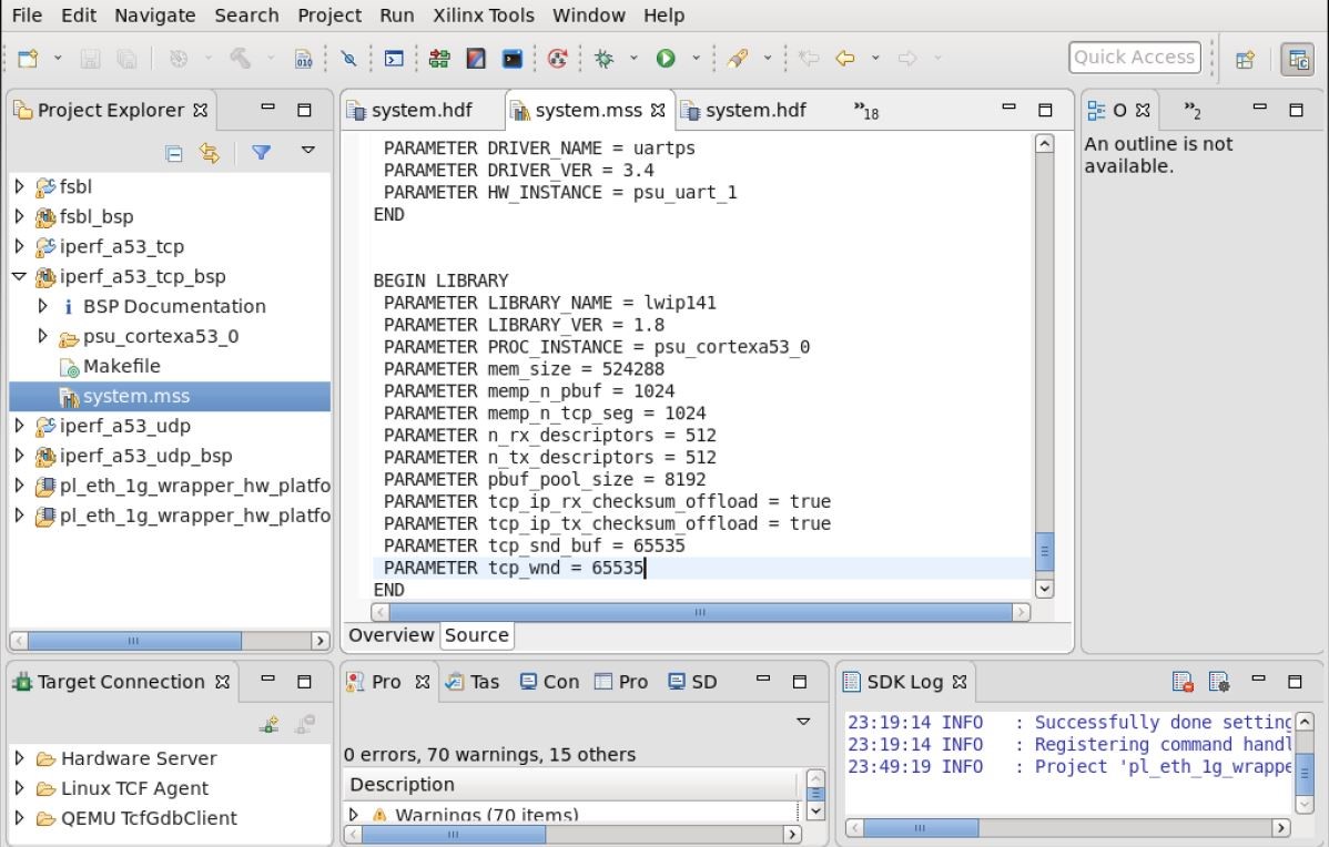
mem_size = 524288
memp_n_pbuf = 1024
memp_n_tcp_seg = 1024
pbuf_pool_size = 8192
n_tx_descriptors = 512
n_rx_descriptors = 512
tcp_ip_rx_checksum_offload = true
tcp_ip_tx_checksum_offload = true
tcp_snd_buf  = 65535
tcp_wnd  = 65535
8) Go to source code of fsbl in work space and apply si570 patch which is part of package.
Then, open FSBL project in Linux shell and use below command to apply patch. This patch is available as part of project package. patch < 001-fsbl-si570-clk.patch
Refresh the fsbl/src folder after applying clock patch.
9) In FSBL source code, there is a file named config_apps.h, below are the configuration for TCP and echo server.
After TCP configuration create Binaries for fir same.
#define INCLUDE_ECHO_SERVER    1
#define INCLUDE_WEB_SERVER     0
#define INCLUDE_TFTP_SERVER    0
#define INCLUDE_RXPERF_SERVER  1
#define INCLUDE_TXPERF_CLIENT  1
#define INCLUDE_TXUPERF_CLIENT 0
#define INCLUDE_RXUPERF_CLIENT 0
Use below configuration for UDP. After UDP configuration create Binaries for the same.
#define INCLUDE_ECHO_SERVER    1
#define INCLUDE_WEB_SERVER     0
#define INCLUDE_TFTP_SERVER    0
#define INCLUDE_RXPERF_SERVER  1
#define INCLUDE_TXPERF_CLIENT  1
#define INCLUDE_TXUPERF_CLIENT 1
#define INCLUDE_RXUPERF_CLIENT 1
10) Build the iperf application and create boot image. Make sure that corresponding processor (A53/R5) is chosen during boot image creation since default processor selected would be A53.
Note: Procedure to build LWIP is common across all design.
4. References
- xapp1305 and xapp1306, PS and PL Ethernet Performance in the Zynq UltraScale+ MPSoC
- UG1085, Zynq UltraScale+ MPSoC Technical Reference Manual
- Netperf , Netperf page