Zynq UltraScale MPSoC Base TRD 2016.4 - Design Module 5
Return to the Design Tutorials Overview.Design Overview
This module shows how to build a Qt video application demonstrating the following features:
- Display via PS DP (DRM framework)
- Video capture from USB webcam or virtual video device (vivid) (V4L2 framework)
- GUI overlay via GPU with OpenGL (using Qt framework)

Design Components
This module requires the following components:
- zcu102_dp_only
- pmu_fw
- petalinux_bsp
- zynqmp_fsbl
- bl31
- u-boot
- kernel
- device tree (system-dm5.dts)
- rootfs
- video_lib
- video_qt2
Build Flow Tutorials
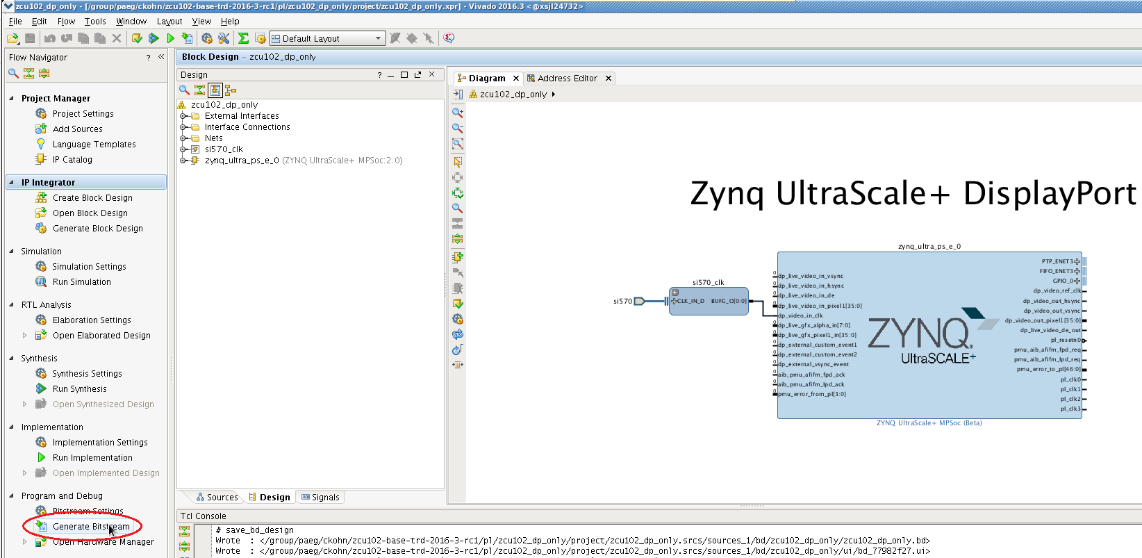
PL DP Only Design
This tutorial show how to build the DP only Vivado design that implements the minimum required to make DisplayPort work.
- Create a Vivado project. Select 'es1' instead if you are targeting a rev D board with ES1 silicon.
% cd $TRD_HOME/pl/zcu102_dp_only
% vivado -s ./scripts/create_project.tcl -tclargs -platform zcu102 -silicon es2
- Implement the design and generate a bitstream
- Copy the generated bitstream to the PetaLinux directory or alternatively use the pre-built bit file that is already bundled with the PetaLinux BSP.
% cp -f project/zcu102_dp_only.runs/impl_1/zcu102_dp_only_wrapper.bit $TRD_HOME/apu/petalinux_bsp/images/linux
PMU Firmware
Please refer to design module 1 - PMU firmware for instructions or skip this step if you have built the PMU firmware in a previous module.
PetaLinux BSP
This tutorial shows how to build the Linux image and boot image using the PetaLinux build tool.
- The petalinux-config step can be skipped if this was already done in a previous module.
% cd $TRD_HOME/apu/petalinux_bsp
% petalinux-config --get-hw-description=./hw-description --oldconfig
- Select the device-tree matching design module 5 and build all Linux image components. If you have run petalinux-build in a previous module, the build step will be incremental.
% cd subsystems/linux/configs/device-tree
% cp system-dm5.dts system-top.dts
% petalinux-build
% cd -
- Create a boot image.
% cd images/linux
% petalinux-package --boot --bif=dm5.bif --force
- Copy the generated boot image and Linux image to the dm5 SD card directory.
% mkdir -p $TRD_HOME/images/dm5/bin
% cp autostart.sh BOOT.BIN image.ub $TRD_HOME/images/dm5
Video Qt Application
This tutorial shows how to build the video library and the video Qt application.
- Set up the Qt environment and generate a Makefile for the Qt project. Make sure the TRD_HOME and PETALINUX environment variables are set before running this step.
% cd $TRD_HOME/apu/video_app/video_qt2
% source qmake_set_env.sh
% qmake video_qt2-dm5.pro -r -spec linux-oe-g++
- Create a new XSDK workspace.
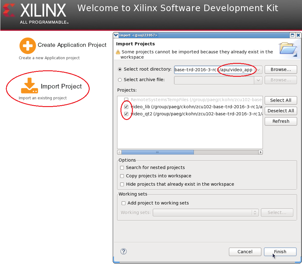
% cd ..
% xsdk -workspace . &&
- Click 'Import Project' from the welcome screen, browse to the current working directory and make sure both the video_lib and video_qt2 projects are selected. Click finish.
- Right-click the video_lib project and select 'C/C++ Build Settings'. Navigate to 'Symbols' and remove the 'WITH_SDSOC' symbol from the defined symbols panel by clicking the delete icon with the red X.

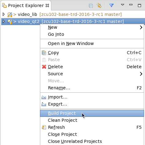
- Right-click the video_qt project and click 'Build Project'.
- Copy the generated video_qt2 executable to the dm5 SD card directory.
% cp video_qt2/video_qt2 video_qt2/run_video.sh video_qt2/video_qt2_wrap.sh $TRD_HOME/images/dm5/bin/
Run Flow Tutorial
- See here for board setup instructions.
- Copy all the files from the $TRD_HOME/images/dm5 SD card directory to a FAT formatted SD card.
- Power on the board to boot the images; make sure INIT_B, done and all power rail LEDs are lit green.
- After ~30 seconds, the display will turn on and the application will start automatically, targeting the max supported resolution of the monitor (one of 3840x2160 or 1920x1080 or 1280x720).
- Upon application exit, use the below login and password to log into the framebuffer or serial console:
root@Xilinx-ZCU102-2016_3 login: root
password: root
- The SD card file system is mounted at /media/card
- To re-start the TRD application type run_video.sh
- The user can now control the application from the GUI's control bar (bottom) displayed on the monitor.
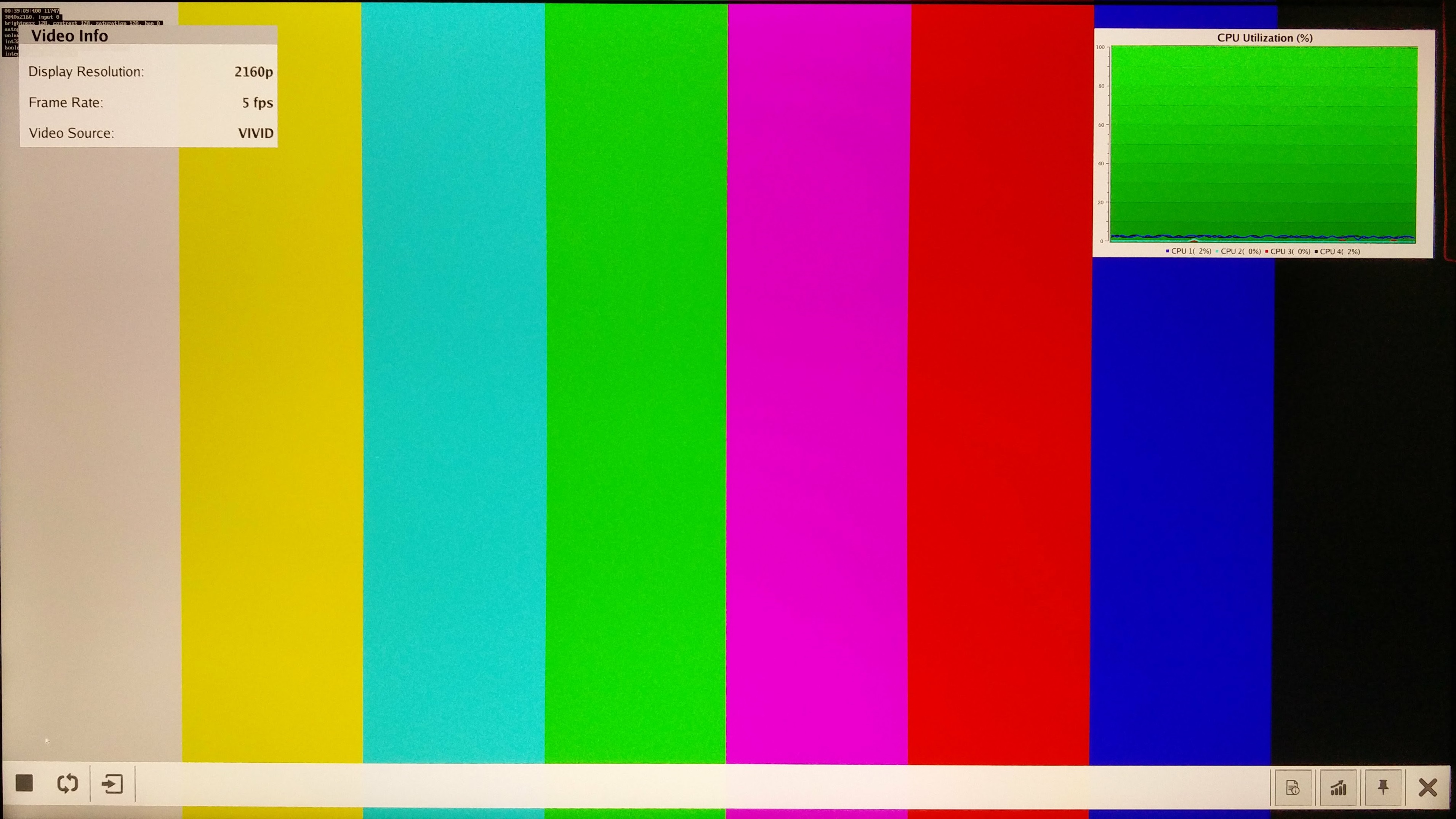
- The following video sources are available:
- Virtual Video Device (VIVID): emulates a USB webcam purely in software
- USB Webcam (UVC): using the universla video class driver
- The video info panel (top left) shows essential settings/statistics.
- The CPU utilization graph (top right) shows CPU load for each of the four A53 cores.