...
Connect the Micro USB cable into the ZCU106 Board Micro USB port J83, and the other end into an open USB port on the host PC. This cable is used for UART over USB communication.
Insert the SD card with the images copied into the SD card slot J100. Please find here how to prepare the SD card for a specific design.
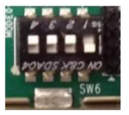
Set the SW6 switches as shown in the below Figure. This configures the boot settings to boot from SD.
Connect 12V Power to the ZCU106 6-Pin Molex connector
Connect one end of HDMI cable to the board’s P7 stacked HDMI connector (upper port) and another end to HDMI monitor
For a USB storage device, connect the USB hub along with the mouse. (Optional)
For SATA storage device, connect SATA data cable to SATA 3.0 port. (Optional)
For MIPI CSI-2, Insert the LI-IMX274MIPI-FMC image sensor daughter card into the FMC0 connector and set VADJ to 1.2V
Important Note: VADJ on the FMC0 connector must be set to 1.2V. See FMC VADJ Voltage Settings for more information
Set up a terminal session between a PC COM port and the serial port on the evaluation board (See the Determine which COM to use to access the USB serial port on the ZCU106 board for more details)
Copy the VCU Single Sensor ROI TRD images into the SD card and insert the SD card on the board
The below images will show how to connect interfaces on the ZCU106 board
...
Build the hardware design
Code Block $ cd $DPU_TRD_HOME/prj/Vitis $ export EDGE_COMMON_SW=<Path to Petalinux Project>/xilinx-vcu-roi-zcu106-v2020.1-final/images/linux/image $ export SDX_PLATFORM=<Path to Vitis Workspace>/zcu106_dpu/export/zcu106_dpu/zcu106_dpu.xpfm $ make KERNEL=DPU DEVICE=zcu106
Generated SD card files are in
$DPU_TRD_HOME/prj/Vitis/binary_container_1/sd_card.(SD Card Format)Copy generated dpu build images from
$DPU_TRD_HOMEdirectory to$TRD_HOMEdirectoryCode Block $ cd $DPU_TRD_HOME/prj/Vitis/binary_container_1/sd_card $ cp bd.hwh BOOT.BIN boot.scr dpu.xclbin Image system.dtb $TRD_HOME/image/boot $ cp rootfs.ext4 $TRD_HOME/image/root
...