Table of Contents
| Table of Contents | ||
|---|---|---|
|
1 Revision History
This wiki page complements the 2018.3 version of the MPSoC VCU TRD.
Change Log:
- Update all projects, IPs, and tools versions to 2018.3
- HDMI Audio integrated into TRD
- Multistream support – Maximum 8 streams (7 HDMI, 1 MIPI)
- PS GEM for stream out and stream in (capture->encode->stream-out <-> stream-in-> Decode→display)
- 10G Ethernet stream out and stream in (capture->encode->stream-out <-> stream-in-> Decode→display)
- Two new MINI reference designs added (HDMI TX and SDI TX )
- HDMI Video captures and Display with SDSoC.
...
This is the main page of VCU TRD wiki, which has links to redirect wiki pages corresponding to individual design modules. It also explains the complete feature list and the supported resources of all the designs. TRD package weblink is provided for the user to download. This page also gives information on required software tools, IP licenses.
The Zynq® UltraScale+™ MPSoC Video Codec Unit (VCU) Targeted Reference Design (TRD) consists of an embedded video encoding/decoding application that runs on the Processing System (PS). The overall functionality of the TRD is partitioned between the Processing System (PS), Video Codec Unit, and Programmable Logic (PL) for optimal performance.
The primary goal of this TRD is to demonstrate the capabilities of the VCU core which is an integrated hard block present in Zynq UltraScale+ MPSoC EV devices. The TRD serves as a platform for the user to tune the performance parameters of VCU and arrives at an optimal configuration for encoder and decoder blocks for their specific use case. The TRD uses Vivado IP Integrator (IPI) flow for building the hardware design and Xilinx Yocto PetaLinux flow for software design. It uses Xilinx IPs and software drivers to demonstrate the capabilities of different components
The TRD supports the following video interfaces:
Sources (up-to 4K-60FPS):
...
- 1G Ethernet PS GEM
- 10G PL Ethernet
The below figure shows the TRD block diagram. It consists of all the Design Modules. The components of each design module are highlighted in unique colors in the diagram. The remaining blocks are common to all design modules as shown.
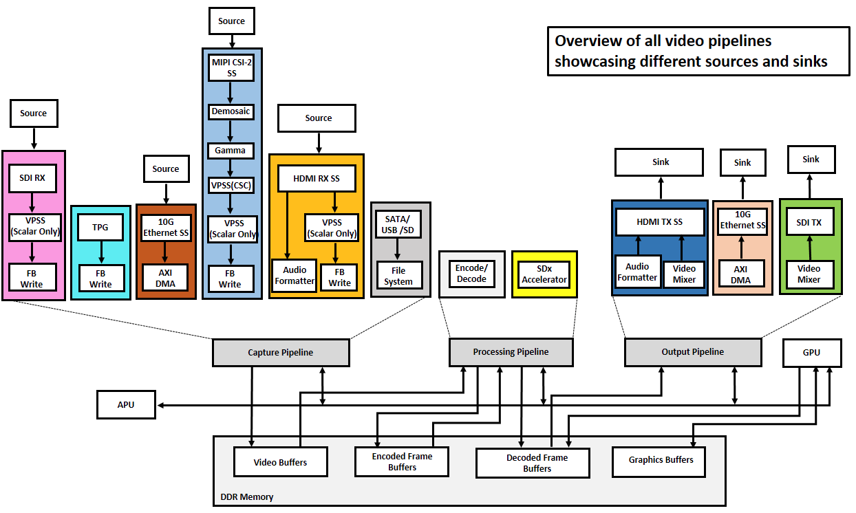
The VCU TRD 2018.3 version consists of nine design-modules as described below. Individual links below will redirect to the corresponding wiki pages and build and run flow of individual designs modules.
...
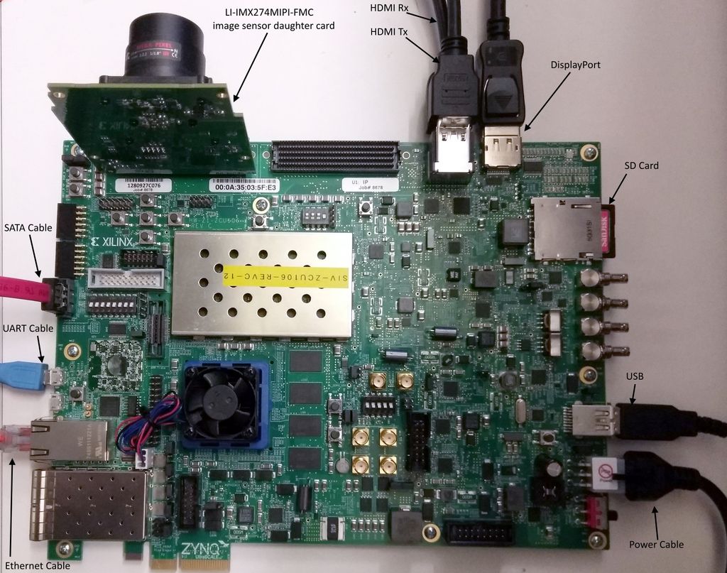
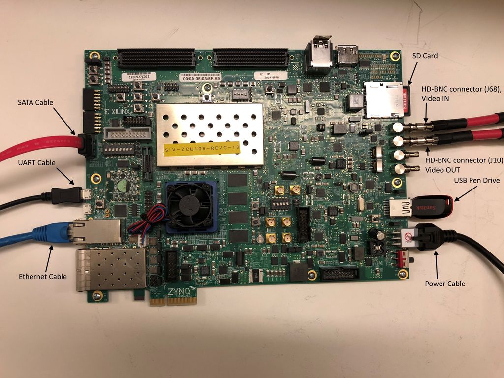
- Connect the Micro USB cable into the ZCU106 Board Micro USB port J83, and the other end into an open USB port on the host PC. This cable is used for UART over USB communication.
- Insert the SD card with the images copied into the SD card slot J100.
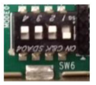
- Set the SW6 switches as shown in the below Figure. This configures the boot settings to boot from SD.
- Connect 12V Power to the ZCU106 6-Pin Molex connector.
- Connect one end of Display Port (DP) cable to board’s U129 connector and the other end to DP port of 4K monitor.
- Connect one end of HDMI cable to board’s P7 stacked HDMI connector (lower port) and another end to HDMI source in case of HDMI design.
- Connect one end of HDMI cable to board’s P7 stacked HDMI connector (upper port) and another end to HDMI monitor in case of HDMI design.
- Connect one end of SDI BNC cable to HD-BNC connector (J68) on board and another end to SDI source in case of SDI design.
- Connect one end of SDI BNC cable to HD-BNC connector (J10) on board and another end to SDI monitor/HDMI monitor with SDI to HDMI Converter in case of SDI design.
- For a USB storage device, connect USB hub along with the mouse. (Optional)
- For SATA storage device, connect SATA data cable to SATA 3.0 port. (Optional).
- For MIPI CSI-2, Insert the LI-IMX274MIPI-FMC image sensor daughter card into the FMC0 connector and set VADJ to 1.2V (See FMC VADJ Voltage Settings).
- Set up a terminal session between a PC COM port and the serial port on the evaluation board (See the Determine which COM to use to access the USB serial port on the ZCU106 board for more details).
- Copy the TRD images into the SD card and insert the SD card on the board.
- The below images will show on how to connect interfaces on ZCU106 board.
...