...
For the individual tutorials, follow the links below:
Required:
Optional:
The reference design has been tested successfully with the following user-supplied components.
Monitors:
HDMI Sources:
USB Webcams:
Note: The Logitech C525 webcam takes about 12 seconds to start after selection from the GUI. It will start streaming once the LED is lit.
DisplayPort Cables:
Storage Devices:
Required:
Steps to generate the license:
The reference design is split into 10 design modules DM1 to DM10:
Each module is described in more detail on the respective tutorial page (see below).
The following table shows the dependency matrix between different modules. For example: DM6 (row) depends on or builds on top of modules DM1 and DM5 (columns).
The top-level directory structure shows major design components. A pre-built SD card image is provide for DM10 along with a basic README and legal notice file.
The below table shows which design components are used in which design modules. A graphical view for each design module is provided on the respective design module tutorial page.
Required:
Optional:
| Anchor | ||||
|---|---|---|---|---|
|
- DM1 Tutorial - APU SMP Linux
- DM2 Tutorial – RPU0 FreeRTOS Application
- DM3 Tutorial – RPU1 Bare-metal Application
- DM4 Tutorial – APU/RPU1 Inter Process Communication
- DM5 Tutorial – APU Qt Application
- DM6 Tutorial – PL Video Capture
- DM7 Tutorial – OpenCV-based Image Processing (Currently Not supported in Vitis)
- DM8 Tutorial – PL-accelerated Image Processing
- DM9 Tutorial – Two Image Processing Functions
- DM10 Tutorial – Full-fledged Base TRD
Software Tools and System Requirements
Hardware
Required:
- ZCU102 evaluation board
- rev 1.0 or rev D2 with production silicon
- Monitor with DisplayPort or HDMI input supporting one of the following resolutions:
- 3840x2160 or
- 1920x1080 or
- 1280x720
- Display Port cable (DP certified) or HDMI cable
- Micro-USB cable, connected to laptop or desktop for the terminal emulator
- Xilinx USB3 micro-B adapter
- adapter shipped with ZCU102 rev 1.0 + production silicon
- adapter needs to be purchased separately for ZCU102 rev D2 with production silicon
- USB mouse
- SD card
Optional:
- HDMI video source with output supporting one of the following resolutions:
- 3840x2160 or
- 1920x1080 or
- 1280x720
- USB webcam
- USB 3.0 hub (supplied with ZCU102 kit)
- Leopard LI-IMX274MIPI-FMC (only supported on rev 1.0 boards)
Compatibility
The reference design has been tested successfully with the following user-supplied components.
Monitors:
| Make/Model | Native Resolution |
|---|---|
| Viewsonic VP2780-4K | 3840x2160 (60/30Hz) |
| Acer S277HK | 3840x2160 (60/30Hz) |
| LG 27UD58 | 3840x2160 (60/30Hz) |
| Dell U2718Q | 3840x2160 (60/30Hz) |
| Dell P2415Q | 3840x2160 (30Hz) |
| Dell U2414H | 1920x1080 (60Hz) |
| GeChic On-Lap1303H | 1920x1080 (60Hz) |
HDMI Sources:
| Make/Model | Resolutions |
|---|---|
| Nvidia Shield TV | 3840x2160, 1920x1080 |
| OTT TV BOX M8N | 3840x2160, 1920x1080, 1280x720 |
| Roku 2 XS | 1920x1080, 1280x720 |
| TVix Slim S1 Multimedia Player | 1920x1080, 1280x720 |
USB Webcams:
| Make/Model | Supported Resolutions | Supported Formats |
|---|---|---|
| Logitech BRIO | 1920x1080 (30fps) | YUYV |
| Logitech HD Pro Webcam C920 | 1920x1080 (5fps), 1280x720 (10fps) | YUYV |
| Logitech HD Webcam C525 | 1920x1080 (5fps), 1280x720 (10fps) | YUYV |
DisplayPort Cables:
- Cable Matters DisplayPort Cable-E342987
- Monster Advanced DisplayPort Cable-E194698
Storage Devices:
- Crucial BX200 2.5in SATA SSD 240GB
- San Disk UltraFit USB3.0 Flash Drive 16 GB
Software
Required:
- Linux host machine for all tool flow tutorials (see UG1144 for detailed OS requirements)
- Vitis Development Environment version 2020.1 (see UG1440 for installation instructions)
- PetaLinux Tools version 2020.1 (see UG1144 for installation instructions)
- Git distributed version control system
- Silicon Labs quad CP210x USB-to-UART bridge driver
- Serial terminal emulator e.g. teraterm
- Reference Design Zip File for ZCU102 rev 1.0 or rev D2 / production silicon including all source code and project files.
Licensing
- Important: Certain material in this reference design is separately licensed by third parties and may be subject to the GNU General Public License version 2, the GNU Lesser General License version 2.1, or other licenses.
The Third Party Library Sources zip file provides a copy of separately licensed material that is not included in the reference design. - You will need only the Vitis license to build the design which includes all the required IP licenses. You can evaluate for 60-days or purchase it here.
Steps to generate the license:
- Log in here with your work E-mail address (If you do not yet have an account, follow the steps under Create Account)
- Generate a license from “Create New Licenses” by checking "Vitis Environment, 60 Day Evaluation License"
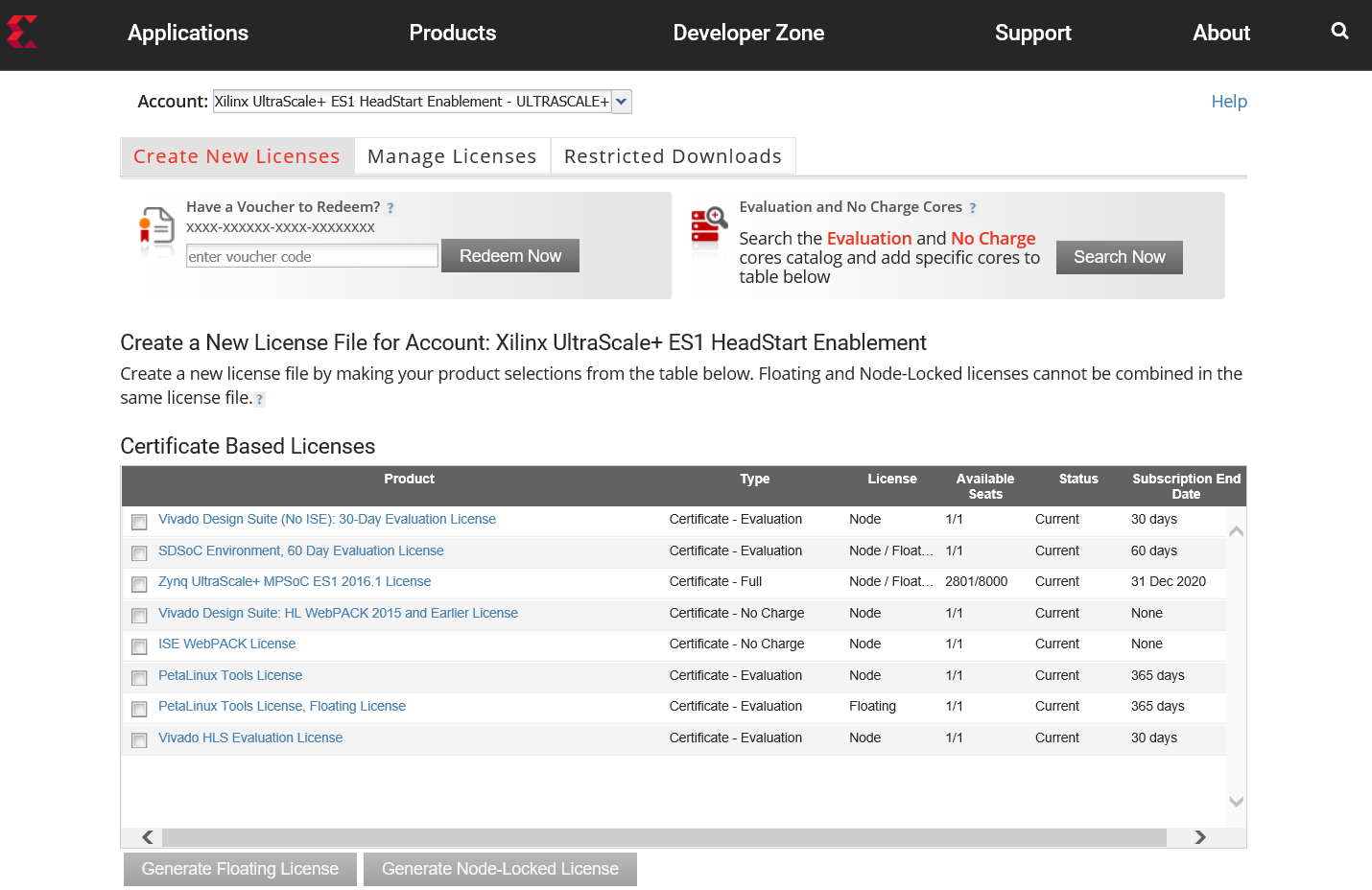
- Under system information, give the host details.
- Proceed until you get the license agreement and accept it.
- The License (.lic file) will be sent to the email-id mentioned in the login details.
- Copy the license file locally and give the same path in the Vitis license manager.
Design Files
Design Modules
The reference design is split into 10 design modules DM1 to DM10:
- DM1 – APU SMP Linux
- DM2 – RPU0 FreeRTOS Application
- DM3 – RPU1 Bare-metal Application
- DM4 – APU/RPU1 Inter Process Communication
- DM5 – APU Qt Application
- DM6 – PL Video Capture
- DM7 – OpenCV-based Image Processing (Currently Not supported in Vitis)
- DM8 – PL-accelerated Image Processing
- DM9 – Two Image Processing Functions
- DM10 – Full-fledged Base TRD
Each module is described in more detail on the respective tutorial page (see below).
The following table shows the dependency matrix between different modules. For example: DM6 (row) depends on or builds on top of modules DM1 and DM5 (columns).
| DM1 | DM2 | DM3 | DM4 | DM5 | DM6 | DM7 | DM8 | DM9 | |
|---|---|---|---|---|---|---|---|---|---|
| DM1 | |||||||||
| DM2 | |||||||||
| DM3 | |||||||||
| DM4 | + | + | |||||||
| DM5 | + | ||||||||
| DM6 | + | + | |||||||
| DM7 | + | + | + | ||||||
| DM8 | + | + | + | + | |||||
| DM9 | + | + | + | + | + | ||||
| DM10 | + | + | + | + | + | + | + | + | + |
Design Components
The top-level directory structure shows major design components. A pre-built SD card image is provide for DM10 along with a basic README and legal notice file.
| Code Block | ||||
|---|---|---|---|---|
| ||||
rdf0421-zcu102-base-trd-2020-1
├── IMPORTANT_NOTICE_CONCERNING_THIRD_PARTY_CONTENT.txt
├── petalinux
│   ├── sdk.sh
│   └── zcu102-prod-base-dm10.bsp
├── README.txt
├── sd_card
│   └── dm10
│       ├── binary_container_1.xclbin
│       ├── BOOT.BIN
│       ├── boot.scr
│       ├── image.ub
│       └── perfapm-server.elf
├── workspaces
│   ├── ws_heartbeat
│   │   ├── heartbeat
│   │   ├── heartbeat_system
│   │   └── hwfile
│   ├── ws_perfapm-ctl
│   │   ├── hwfile
│   │   ├── perfapm
│   │   ├── perfapm-ctl
│   │   └── perfapm-ctl_system
│   └── ws_perfapm-server
│       ├── hwfile
│       ├── perfapm
│       ├── perfapm-server
│       └── perfapm-server_system
└── zcu102_base_trd
    ├── hw
    │   └── zcu102_base_trd.xsa
    ├── samples
    │   ├── filter2d_optflow
    │   ├── filter2d_pl
    │   └── opticalflow
    ├── sw
    │   ├── prebuilt
    │   ├── zcu102_base_trd
    │   └── zcu102_base_trd.spfm
    └── zcu102_base_trd.xpfm
|
| Design Component | Design Module | |||||||||
|---|---|---|---|---|---|---|---|---|---|---|
| DM1 | DM2 | DM3 | DM4 | DM5 | DM6 | DM7 | DM8 | DM9 | DM10 | |
| heartbeat | Y | Y | ||||||||
| perfapm-ctl | Y | |||||||||
| perfapm-server | Y | Y | ||||||||
| perfapm-client | Y | |||||||||
| video-qt2 | Y | Y | Y | Y | Y | Y | ||||
| gstsdxfilter2d | Y | Y | Y | Y | ||||||
| gstsdxopticalflow | Y | Y | ||||||||
Tutorials
Board Setup
| Anchor | ||||
|---|---|---|---|---|
|
Required:
- Connect power supply to 12V power connector.
- Connect USB mouse via USB hub to the USB3 micro-AB connector.
- Display
- Connect a DisplayPort cable to DisplayPort connector on the board; connect the other end to a monitor OR
- Connect an HDMI cable to HDMI Tx connector (top) on the board; connect the other end to a monitor
Note: Make sure you only connect either DP or HDMI Tx on the board, not both, otherwise the design might malfunction - Connect micro-USB cable to the USB-UART connector; use the following settings for your terminal emulator:
- Baud Rate: 115200
- Data: 8 bit
- Parity: None
- Stop: 1 bit
- Flow Control: None
- Insert SD card (FAT formatted) with binaries copied from
$TRD_HOME/images/dm10directory.
Optional:
- Connect a USB webcam to the USB hub.
Note: The USB webcam needs to output YUYV pixel format. Other formats are not supported in this design. - Connect an HDMI cable to HDMI Rx connector (bottom) on the board; connect the other end to an HDMI source
- Connect the LI-IMX274MIPI-FMC module to the HPC0 FMC connector on the board
Note: The design only supports this FMC on rev 1.0 boards. Vadj needs to be set to 1.2V for correct operation of the daughter card. If the FMC card does not seem functional, please follow the instructions explained in Answer Record AR67308 to check and/or set Vadj.
Jumpers & Switches:
- Set boot mode to SD card:
- Rev 1.0: SW6[4:1] - off,off,off, on
- Rev D2: SW6[4:1] - on, off on, off
- Configure USB jumpers for host mode
- J110: 2-3
- J109: 1-2
- J112: 2-3
- J7: 1-2
- J113: 1-2
...