Zynq-7000 AP SoC Spectrum Analyzer part 5 - Accelerating Software - Accelerating an FFT with ACP Coprocessor Tech Tip
Zynq-7000 AP SoC Spectrum Analyzer part 5 - Accelerating Software - Accelerating an FFT with ACP Coprocessor Tech Tip
Table of Contents
Document History
| Date |
Version |
Author |
Description of Revisions |
|
| 16 September 2013 |
1.0 |
Faster Technology |
Initial posting with figures |
|
| 22 October 2013 |
1.1 |
Faster Technology |
Revision to include starting files set & additional support files |
|
| 1 March 2014 |
1.2 |
Faster Technology |
Update to 2013.4 Release |
|
| Date |
Author |
Comment |
||
|---|---|---|---|---|
| More Revisions |
||||
Description/Summary
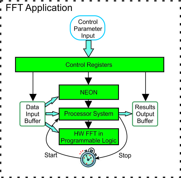
In Tech Tip "Zynq Building an FFT Application Tech Tip" an FFT application was created to run on both the ARM processor and the NEON SIMD engine of the Zynq-7000 AP SoC. Execution time comparisons were captured demonstrating a speed up of 1.25 to 1.85 using the NEON SIMD engine versus the ARM processor. In this Tech Tip we will expand that application to include a hardware FFT unit in the PL fabric to demonstrate the additional 9.3X speed up that is possible with the tightly coupled hardware co-processing capabilities of the Zynq-7000 AP SoC versus execution on the NEON SIMD engine. In addition, this Tech Tip will demonstrate use of the IP Integrator (IPI) capability in Vivado for creation of the overall system being utilized.
Key techniques that will be illustrated with this Tech Tip include:
- Information passing between the PS and PL using DMA through the high speed ACP port to maximize performance
- Use of IP Integrator to build the Hardware FFT in PL from building blocks in the standard library
- Status flag operations between the PL hardware and the operating software in the PS
- Mapping between virtual addresses used in Linux and physical addresses required by hardware operations
Implementation
| Implementation Details |
|
| Design Type |
PS & PL |
| SW Type |
Linux |
| CPUs |
1 CPU - standard ZC702 frequency |
| PS Features |
ARM Processor and NEON SIMD engine, OCM, DDR and other peripherals in standard OSL Linux |
| PL Cores |
Hardware FFT |
| Boards/Tools |
ZC702 |
| Xilinx Tools Version |
Vivado / SDK 2013.4 |
| Other Details |
Standard ZC702 setup for console terminal and Ethernet required |
| Files Provided |
|
| zynq-fft.zip |
FFT Application source code files |
| HWfft.zip |
Vivado 2013.4 files to build Hardware FFT block in PL |
| fftApp.zip |
Optional starting point workspace file set |
| u-boot.zip |
Optional u-boot.elf file to build BOOT.BIN |
Block Diagram
Step by Step Instructions
This Tech Tip proceeds in two major operations; building the Hardware FFT and then building the software that controls and uses the Hardware FFT in conjunction with the software in the PS.
As noted above, Vivado 2013.4 will be used to create the hardware FFT used in this Tech Tip.
All of the required files to build the hardware are in the HWfft.zip file noted above. Download that file to the directory where you are building the hardware for this Tech Tip. This does not need to be in the same directory structure as the workspace used by SDK for building the software. In our case this is:
G:\ZC702fft
NOTE:
Because of the possibility of very long path names being generated by Vivado in the elaboration of the various IP blocks, it is a strong suggestion to keep the starting directory name very short and close to the root of the drive being used. Odd errors can occur in the design implementation steps if the path names become too long.
With the download completed, unzip HWfft to the location where the hardware will be built.
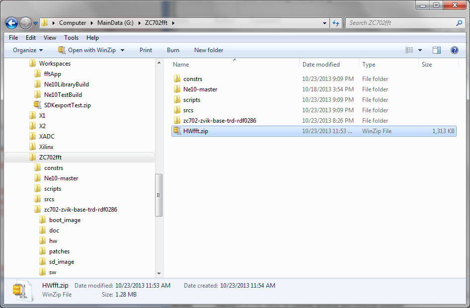
The base directory where the HWfft.zip files are saved is referred to as $ZYNQ_TRD_HOME. In our case then $ZYNQ_TRD_HOME is G:\ZC702fft. If you have a different base directory, note that it will be used where $ZYNQ_TRD_HOME is referenced.
This Tech Tip will proceed in two main sections; using Vivado to build the hardware, and using SDK to build the software. The result will be a revised boot file for the ZC702 that contains updated hardware for the base TRD with the hardware FFT and an application file that builds on the capabilities of the "Zynq Building an FFT Application Tech Tip".
Building the hardware
Supplied with this Tech Tip is a tcl script file that will simplify the process of building the hardware FFT in Vivado. This file is:
project.tcl
The file is supplied within the HWfft.zip that was previously obtained and un-zipped. Verify that it is in the /scripts folder.
We then run Vivado to build the hardware system.
On Windows, select Start > All Programs > Xilinx Design Tools > Vivado 2013.4 > Vivado 2013.4
Vivado will start and show the welcome screen

CAUTION:
Before starting the process of building the hardware, verify that you have installed valid hardware licenses for the IP cores used in the ZC702 Base TRD design. These include the Chroma-Resampler, Video Timing controller, etc. If a hardware implementation license is not in place when bitstream generation starts, the whole project will need to be deleted and started from the beginning.
In the tcl console input line, run the following commands
cd $ZYNQ_TRD_HOME - in our case this is cd G:/ZC702fft
source ./scripts/project.tcl - project.tcl will build the complete base TRD hardware system with the PS and various video processing hardware blocks used by the TRD software.
If you encounter any licensing issues or other implementation errors in running the project.tcl script, these must be resolved before running the add_bd_fft.tcl script. Otherwise the hardware will not build properly.
After running the project.tcl script successfully (there will likely be some warnings), you should have the following with the FFT block connected into the TRD blocks:
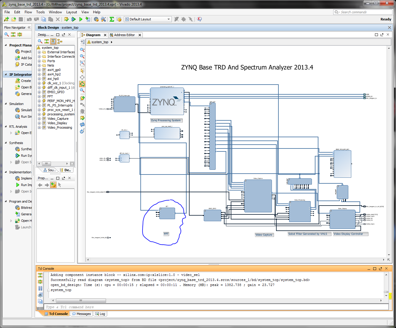
IP Integrator has both placed the functional blocks but also connected them with their corresponding signal bundles to the other blocks in the design. This greatly simplifies the process of generating a complex design and assuring that the components are connected properly. Any block of logic created from scratch or configured within Vivado can be saved as a reusable IP core for later use. See the Vivado IP Integrator documentation for details on how this is done.
In the diagram pane, we can zoom into the hardware FFT to see what it contains. Move the cursor to hover over the upper left corner of the FFT block. When it changes to double chevrons, click to expand the hierarchy of the FFT IP core.
Using the zoom controls, either the magnifying glass with the + or selecting and dragging a zoom window in the diagram pane, zoom in to better see the contents of the FFT block. It is also useful to maximize the diagram pane (click the maximize icon in the upper right corner).
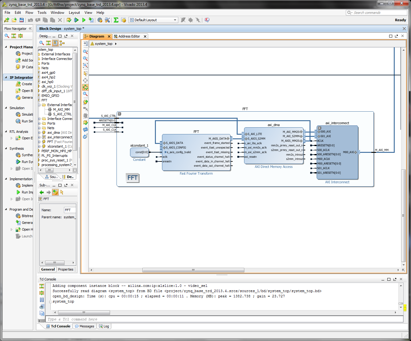
The FFT block is a standard IP core that is configured through the Core Generator. In this instance it is configured to perform a 4096 FFT to match the largest FFT size that we previously supported in software execution. This will enable us to compare results between the various implementation options.
The axi_dma block is used to move the data from the PS into the FFT core and then back to the PS. It also performs the critical function of converting between the memory mapped format of the AXI interconnect and the streaming format used by the FFT core. The memory based FFT data uses physical addresses versus the virtual addresses used by Linux in the PS. Thus, the requirement for virtual to real address translation in the operating software.
Data to or from the AXI DMA core flows through the ACP port on the AXI interconnect structure. Note that there is also a slow speed interface to the AXI DMA block. This is for control and status communication between the hardware and the operating software in the PS. It is through this mechanism that the signal flags to start the FFT and that the FFT is complete are passed.
With successful completion of the tcl script, all of the configuration is complete and the design is ready for use.
To complete the hardware design, synthesis and implementation must be run. This can be done by initiating each step individually or if "Generate Bitstream" is selected, the Synthesis and Implementation steps will be run automatically.
In the flow Navigator panel, click Generate Bitstream (in the Program and Debug group at the bottom of the panel)
Synthesis, implementation and bitstream generation may take as long as two hours for this design. There will be some warnings, but these are not critical to the proper operation of the hardware. Most notably, there are a number of optional ports on some of the IP blocks that are not required and are therefore not mapped into the processor address space. If the following message appears, click OK to accept it and allow the synthesis to continue.
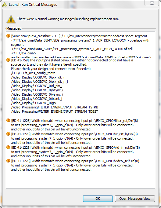
When Vivado completes processing the design, verify that there are no errors; warnings are expected with most relating to optimizations that are being done and have no impact on operation of the hardware. In the "Bitstream Generation Completed" accept the "Open Implemented Design option and click OK.

Vivado will then display the chip view of the implemented design
The next step is to export this hardware design in a form that SDK can use to build the files needed to properly configure the ZC702 to run the hardware FFT.
The block diagram must be in view. If it is not in view, expand the IP Integrator category in the Flow Navigator pane, click on Open Block Design and select system_top.bd.
With the block diagram in view, we can perform the export to SDK.
From the File menu select
File > Export > Export Hardware for SDK
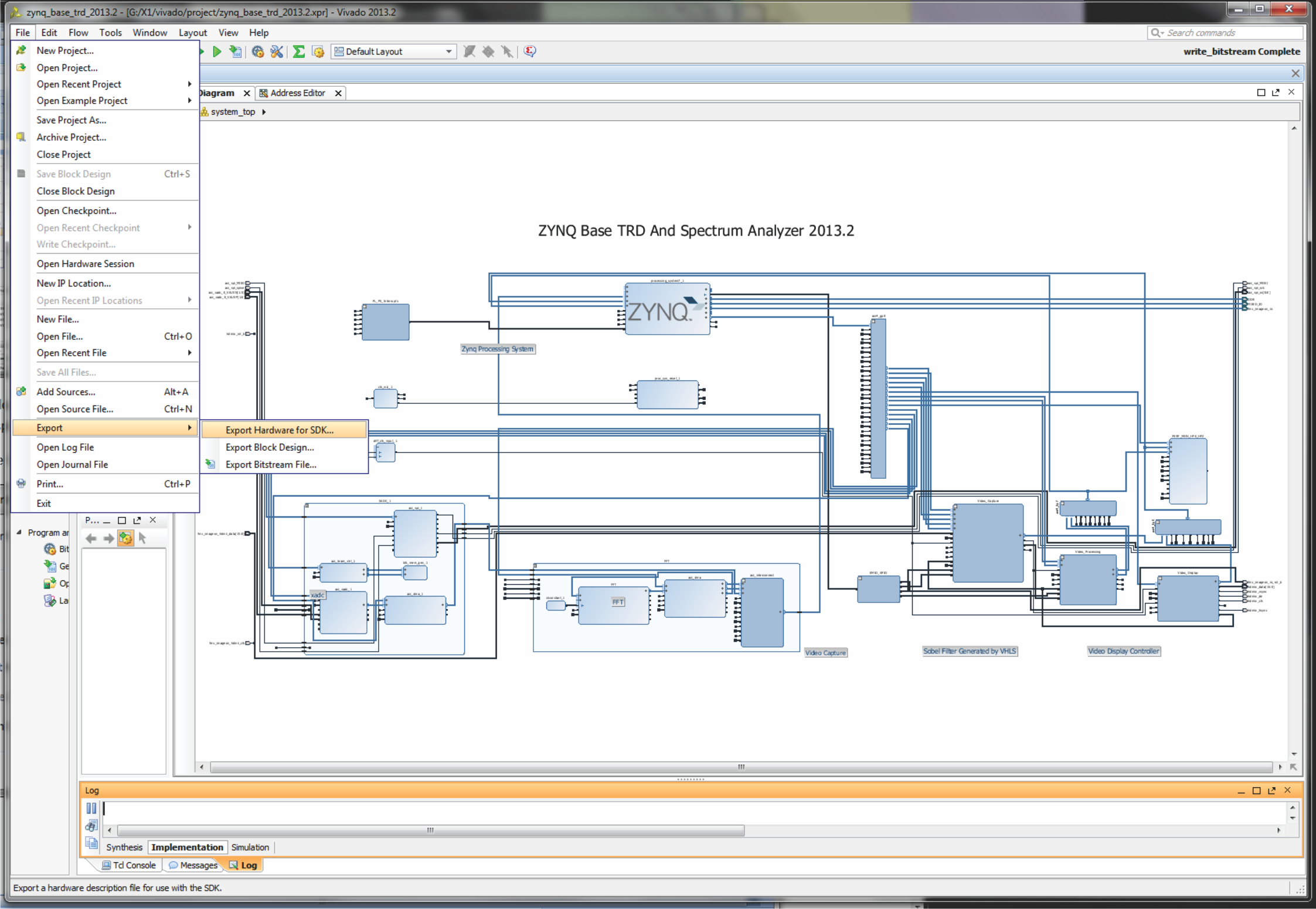
NOTE: If the block diagram is not displayed, the export option will not be visible. Select Window > Diagram to display the block diagram if it is not in view.
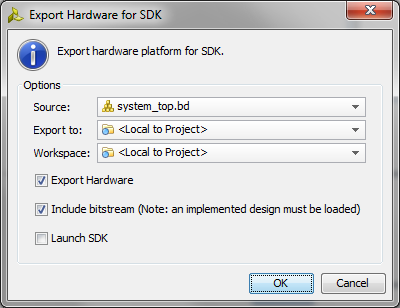
In the dialogue box that appears, leave the defaults selected and click OK. The option to Include bitstream should be visible and checked. This is convenient as it enables Vivado to put all of the information required in a single location.
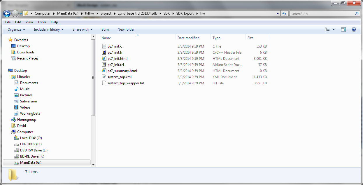
Vivado creates several hardware description files and the bitstream in a directory branch off of the "project" area as shown below. The files in this branch will be used in the next step so remember where they are.
At this point, we are done with Vivado and it can be closed. Save the project for future reference if prompted.
Building the Software
With the hardware for the FFT in the PL fabric complete and included in the base TRD hardware, we need to build the software to move data into and out of the FFT block. Recall from the block diagram that the data movement in the PL is controlled by a DMA block. The software for operating the hardware FFT is simply the driver to start the DMA, then wait for the FFT to complete and the DMA to deliver the results back. Simple polling supported in Linux with the "while" construct will be used for this polling operation.
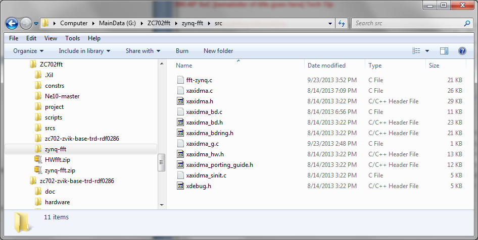
The various software source files required are in the compressed file "zynq-fft.zip" that is associated with this Tech Tip. Download this zip file from the Xilinx wiki and unzip it to a convenient location on your hard drive. In our case, we put it in our current working directory G:\ZC702fft.
These source files and the files exported from Vivado will be used to build two things required for the hardware FFT
- a new BOOT.bin file, part of the boot process, that contains the bitstream and other hardware related information to construct the hardware system
- the executable application; an extension of the prior application that adds the hardware FFT option
Building a new BOOT.bin
At the conclusion of the Tech Tip "Zynq Building an FFT Application Tech Tip" the workspace contains the library of signal processing functions built in the Tech Tip "Zynq Ne10 Library Tech Tip"and tested in the Tech Tip "Zynq Ne10 Testing Tech Tip". It also has the tested application code for the FFT application. This Tech Tip is built upon that existing workspace. If you have that workspace in place, skip to the instructions to start SDK after the workspace is in place (below the heading "Old Workspace in Place").
If the workspace is not available, or if there is any question if it was completed properly (or you simply want to skip those earlier steps), the referenced file fftApp.zip can be used to create a known working starting point for this Tech Tip.
Download the zip file from the fftApp.zip link.
Create an empty directory where you will be implementing this Tech Tip. To be consistent with the balance of these step by step instructions, the directory could be:
G:\ZC702fft\zc702-zvik-base-trd-rdf0286
However, these steps to import a known workspace will work with any new folder of the user's choosing.
CAUTION:
Many users have unusual problems with SDK when using different directory structures and names. If you encounter any odd behaviors with SCK, it is advised to use the suggested directory structure and names.
Start SDK
Start -> All Programs -> Xilinx Design Tools -> Vivado 2013.4 -> SDK -> Xilinx SDK 2013.4
In the Workspace Launcher, browse to and select the previously created empty folder. In our case, that is G:\ZC702fft\zc702-zvik-base-trd-rdfo281\sw.
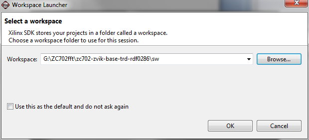
Click OK to continue
If you are presented with a Welcome tab, close it by clicking on the x on the tab.

SDK will start with a blank Project Explorer pane
Select File -> Import
The Import dialogue box will appear. Expand the General line and select Existing Projects into Workspace
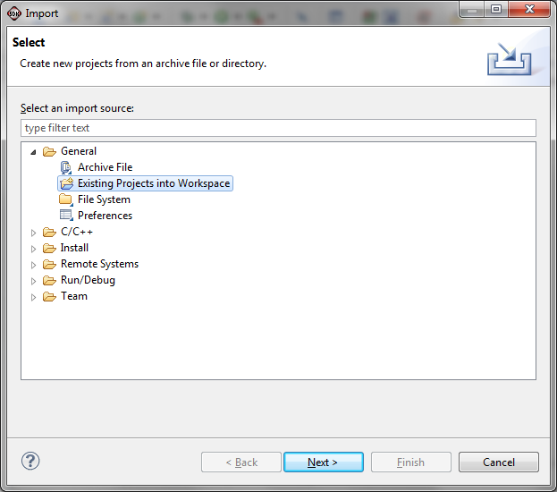
Click Next
Click the Select archive file button. Then click Browse to navigate to the saved workspace file that you want to import and click Open. In our case this is fftApp.zip.
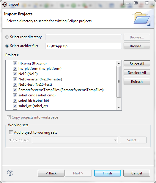
Click Finish
SDK will build the workspace automatically. Because SDK is already started and the workspace is in place, you can skip the following instructions on starting SDK and go directly to after SDK is running with the workspace in place (Starting Projects Ready).
Old Workspace in Place
The first step in building our new BOOT.bin is to bring the new hardware information from Vivado into SDK. We start with the workspace that resulted from the completion of the "Zynq Building an FFT Tech Tip".
Start SDK
On Windows, select Start > All Programs > Xilinx Design Tools > Vivado 2013.4 > SDK > Xilinx SDK 2013.4
When the Workspace Launcher appears, be sure that it is pointed to the workspace used for the "Zynq Building an FFT Application Tech Tip".
Click OK
Starting Projects Ready
SDK should have the files and projects in place as we last saw them. If it has changed, use the known working workspace from above or repeat the various steps to be sure this is a tested working set of files and projects before proceeding.
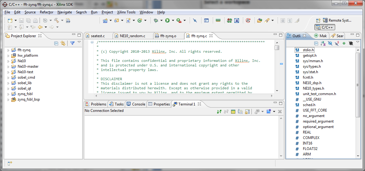
The new hardware will impact the hw_platform and the zynq_fsbl_bsp, both of which are used to build the zynq_fsbl, a key file in building a new BOOT.bin.
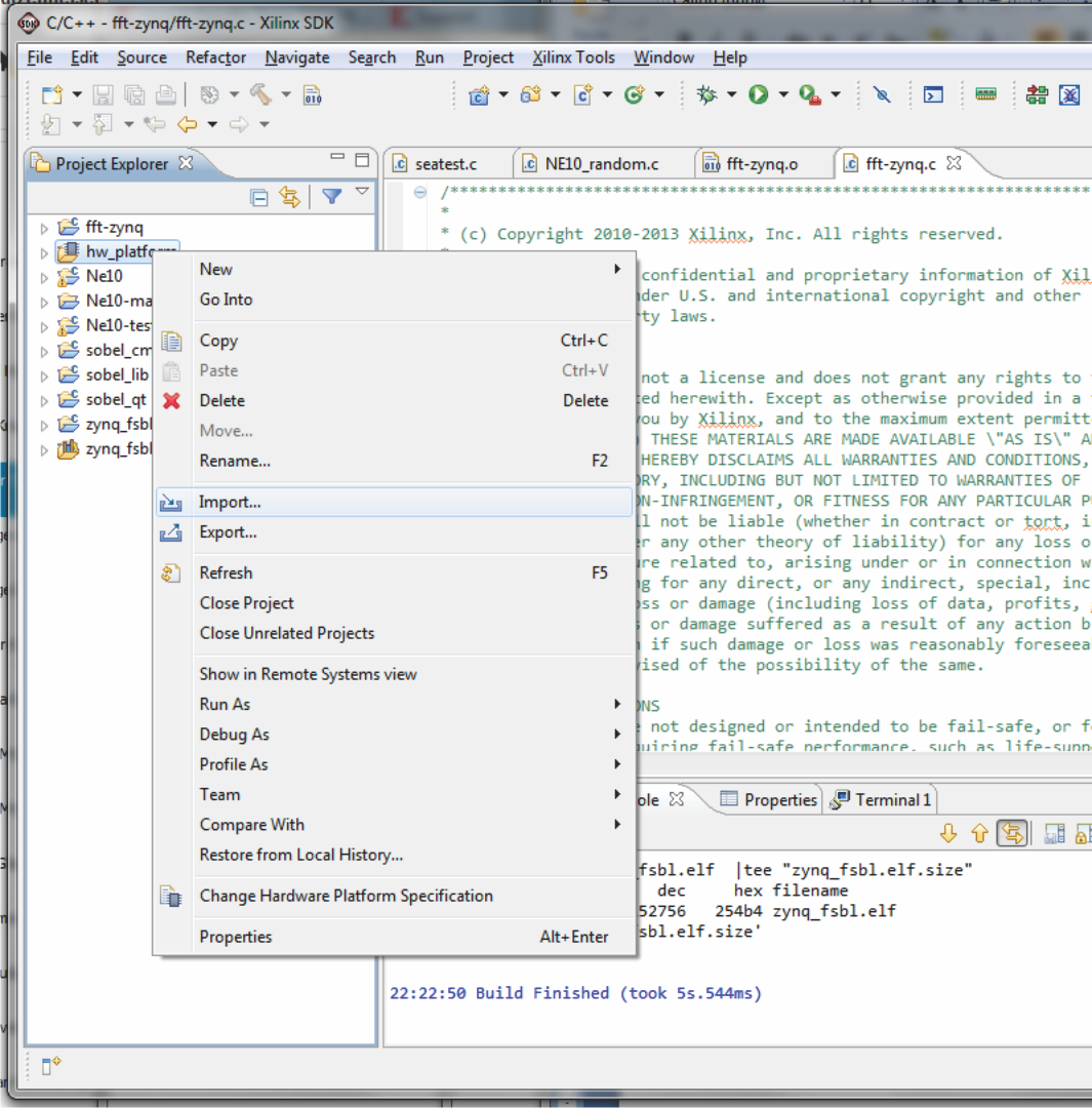
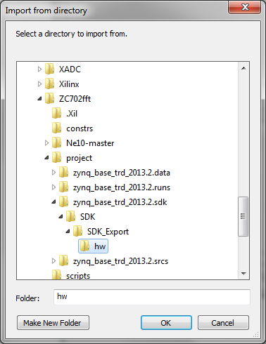
Select hw_platform in the Project Explorer pane, right click on it and select "Change Hardware Platform Specification". When the pop up box appears, read the cautions and click Yes.

Click Browse and follow the path from the $ZYNC_TRD_HOME used earlier to the following directory off of that location:
project/zynq_base_trd_2013.2.sdk/SDK/SDK_Export/hw
SDK will show system_top.xml as an available file.
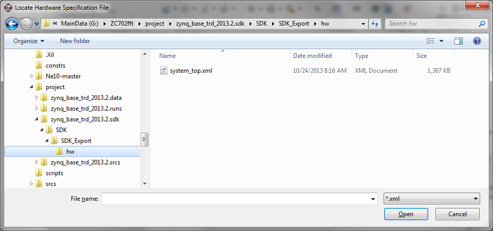
Select system_top.xml
Click Open and then OK
The file will be read and SDK will build new hardware information from the imported xml file. If the build process does not start automatically, this indicates that the option is not set up for automatic builds. To change this, from the top menu bar select Project. If Build Automatically is not checked, then the builds will need to be done manually. For the balance of this Tech Tip, we assume that Build Automatically is NOT checked. If it is currently checked, click on it to uncheck that option.
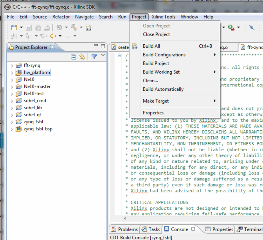
If the Build Automatically option was not checked, that is acceptable at this point. Other steps will also build the required projects.
In addition to changing the Hardware Specification, we need to import the balance of the files that define the new hardware.
Select hw_platform in the Project Explorer pane and select Import
Select File System and click Next
At the From Directory box click Browse and navigate to the directory where Vivado exported the hardware to SDK.
Click OK
SDK will populate the Import file list with all of the hardware information files. In the left pane, click on the folder labeled hw to select all of the files.
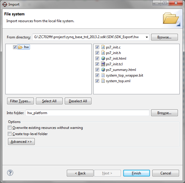
Be sure the Into Folder: displays hw_platform. If it does not, cancel from this screen and start again from the point of selecting hw_platform and right clicking to get the context sensitive menu.
With the other options at their defaults, click finish.
Because some of the new files are replacements for the older ones, a warning message will appear.
Click "Yes to All" to proceed.
Expand hw_platform to verify that the import performed correctly.
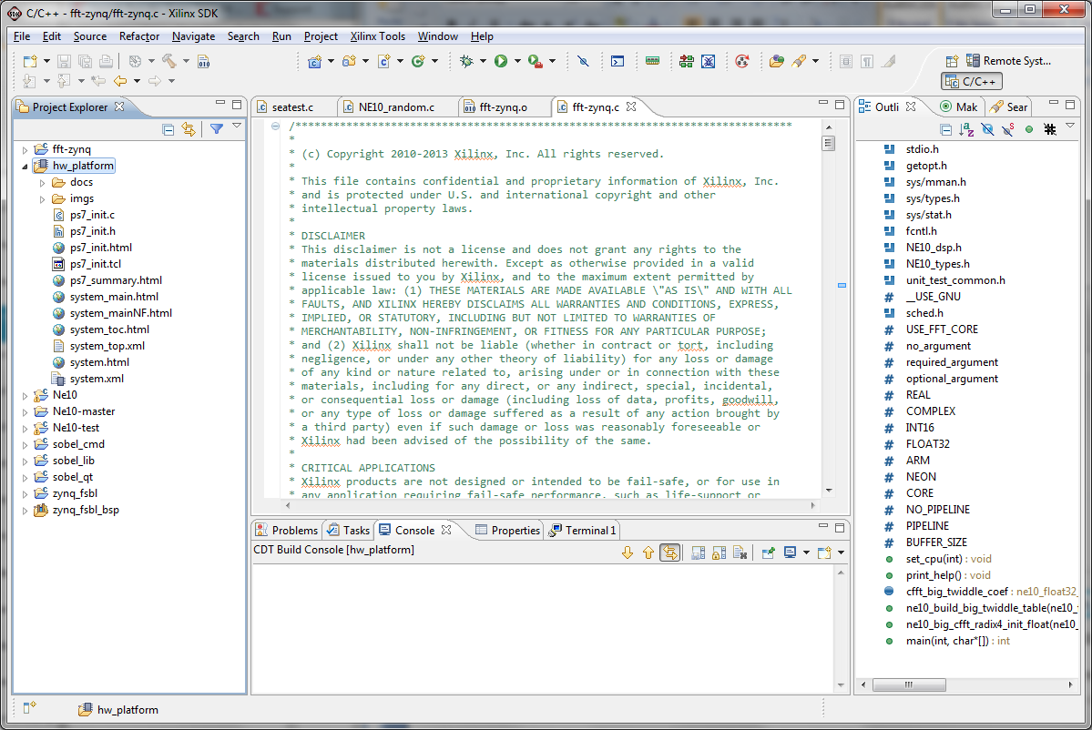
The main file that is critical at this point is the zynq_fsbl (first stage boot loader). To be sure that it is built with the latest information, force SDK to build it at this point.
Set the build options to Release before building zynq_fsbl.
Select zynq-fsbl in the Project Explorer pane, right click on it and select Build Configurations > Set Active > Release
Select zynq_fsbl in the Project Explorer pane, right click and then select "Clean Project".
When this completes, right click on zynq_fsbl again and then click "Build Project".
This build creates the zynq_fsbl.elf file. Verify that this file has been created and is new by expanding the zynq_fsbl project, then expanding the Binaries sub-directory. Right click on zynq_fsbl.elf and select properties. The information should reflect the fact that this file was just recently modified.
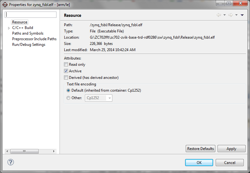
Click Cancel to return to SDK.
With the new zynq_fsbl in place, we can create the new boot file required to invoke the hardware FFT in the PL of the ZC702.
A special utility that creates the new boot image can be started in at least two ways a) from the top menu bar, select Xilinx Tools > Create Zynq Boot Image or b) with zynq_fsbl selected in Project Explorer, right click on zynq_fsbl and select "Create Boot Image" from the pop up menu
With either method, the following dialogue will appear
Because we had zynq_fsbl selected, SDK will automatically populate the FSBL elf entry. While it is possible to use this utility with external zynq_fsbl files, we will not go into that at this point.
The output folder by default will a sub-folder under the zynq_fsbl project. This is fine for this Tech Tip but the output could be written to any location on your computer if desired.
Three files are required for creation of a new boot image file:- a first stage boot loader file - zynq_fsbl.elf as already indicated above- a valid bitstream file for the target device - this was produced earlier by Vivado - a valid u-boot.elf file that will start Linux for our application to run (other u-boot.elf files are possible for stand-alone operation)
In addition, these three files MUST in the order stated above for proper boot operation!
In this example, because we had zynq_fsbl selected when the Create boot image command was invoked, SDK has automatically populated the Boot Image Partitions: list box with the bitstream file as the first entry and the bootloader file zynq_fsbl.elf as the second file.
CAUTION!
These two files are in the incorrect order. If the Boot image partitions list is populated with both of these files, select the system.bit entry and click the Delete button on the right side (The Up and Down buttons might also be used but they are not active at this time.)
We then need to add the bitstream file and the u-boot file to complete the set.
Click the Add button and the Add partition dialogue will appear.
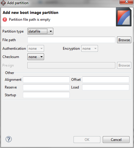
With the Partition type set to datafile, click Browse and navigate to the location where the bitstream from the hardware creation process was stored. In our case this is G:\HW4tt\project\zynq_base_trd_2013.4.sdk\SDK\SDK_Export\hw
Click on the bit file - system_top_wrapper.bit and click OK
When the Add partition dialogue appears, click OK
This will add the bitstream file as the second item in the list.

We need to specify the u-boot.elf file as the last item.
We will use the u-boot.elf file supplied with the base TRD as that will properly initiate the Linux loading and setup of the balance of the system that our application code expects. This is in a boot image directory in the base TRD un-zipped file structure.
If you do not have the base TRD files, a copy of the u-boot.elf file is associated with this Tech Tip. Download it and unzip it to the base directory you are using and navigate to that file in the next step.
Click Add and the Add Partition dialogue box will appear.
Be sure that the Partition type dropdown list is set to datafile.
Then select Browse and navigate to the base TRD and then to the boot_image sub-directory(or to the directory where you unzipped the provided u-boot.elf file)
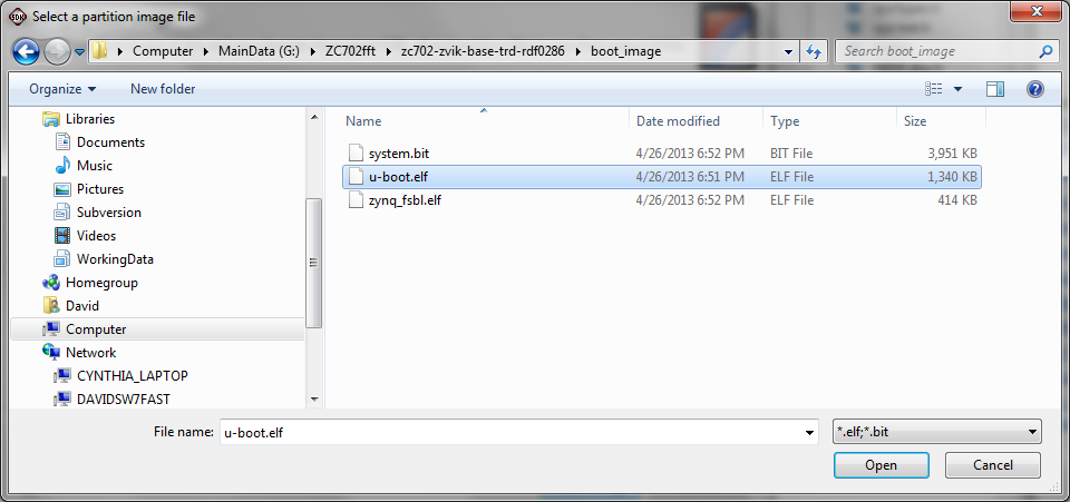
Select u-boot.elf and click Open
When the Add Partition dialogue reappears, click OK.
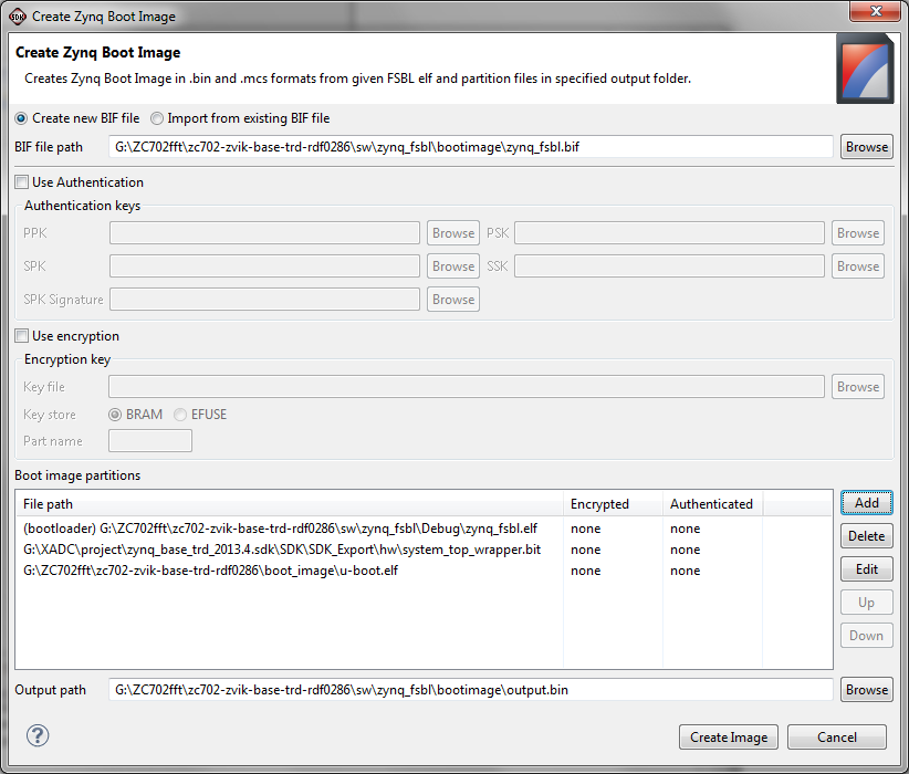
We now have the three required files for creation of the boot image. Note that they are in the correct order.
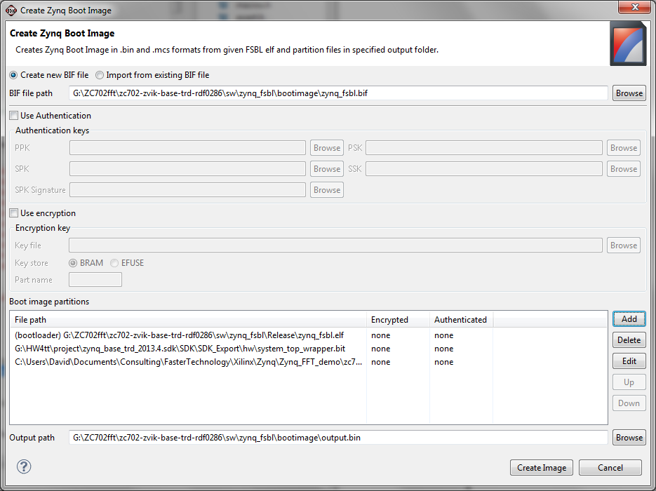
Click the Create Image button at the bottom of the dialogue box.
SDK will create the new boot file and store it in the bootimage directory under the zynq_fsbl project.
To work properly with the ZC702, this boot file MUST be named BOOT.bin
To rename the output.bin file, right click on it in the Project Explorer pane, change the name to BOOT.bin and click OK.
With the new boot file in place, we then build the application software that adds support for the hardware FFT.
Building the Application Software
Recall that earlier we downloaded and unzipped a set of files into a zynq-fft directory on our computer. We now use those to build the software application that uses the new hardare FFT.
Because we started with the workspace where we built the software for the "Zynq Building an FFT Application Tech Tip", we already have a fft-zynq project defined. We will simply replace the key files in that project to add the hardware FFT capability.
Select the fft-zynq project in the Project Explorer window and Right Click on it. From the pop up menu, select Import. In the Import select dialogue box, expand the General category and select File System.
Click Next
Adjacent to the From directory: entry box, click Browse
Navigate to where you saved the application source files; in our case ZC702fft\zynq-fft
Select the src directory and click OK
The set of files that are required will be listed. Click the box next to the folder icon src in the left pane to select all of the files.
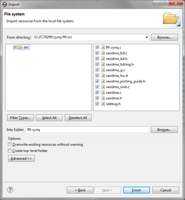
Be certain that the Into folder: is set to fft-zynq.
Click Finish to import the files
There will be a warning about overwriting files. Click the "Yes To All" button to proceed.
SDK may flag some errors or warnings as it imports these files. These can be ignored for now as they will be resolved by changing the include paths for the application build process.
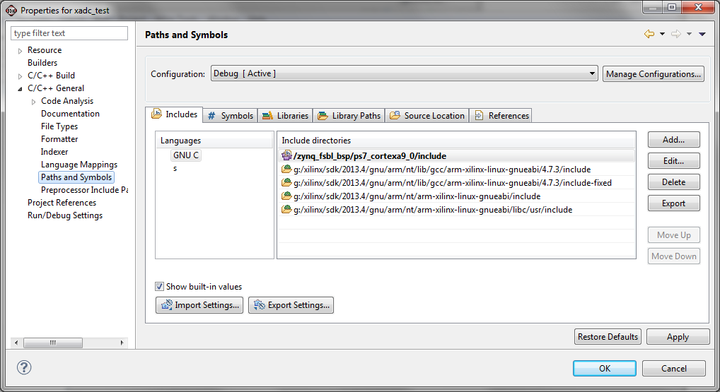
Right click on the fft-zynq project in the Project Explorer pane. From the pop up menu, select C/C++ Build Settings
Expand the C/C++ General category and then select Paths and Symbols.
Some paths will already be set from the prior Tech Tip work. We need to add two paths to the existing set to enable our new application software to build properly.
Click the drop down arrow for the Configurations line and select All Configurations
Click the Add button on the right side of the dialogue box
In the Add directory path dialogue box, click both of the options then click the Workspace button and select fft-zynq and click OK
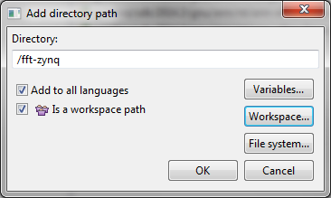
Click OK again to add this path.
Using the same Add process, add the path zynq_fsbl_bsp/ps7_cortexa9_0/include
Click Apply
When the warning message appears regarding indexing, click Yes.
Click OK to finish adding the paths
To achieve the best execution speed we need to set the default build options to Release.
Right click on the fft-zynq project in the Project Explorer pane.
Select Build Configurations > Set Active > Release
We can now build the application software.
Right click on fft-zynq and select Clean Project from the pop up menu. When that completes, right click on fft-zynq and select Build Project from the pop up menu. SDK will then build the new application software.
Testing the hardware FFT
With the new BOOT.bin and fft-zynq.elf application files completed, we can test them and compare the execution times of all 3 methods of processing the FFT.
The BOOT.bin file replaces one already on the SD card used to boot the ZC702. With the power to the ZC702 OFF, remove the SD card and insert it in a SD card reader or media slot on your computer. The files on the card should be at least this set
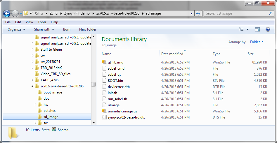
If the files are different in any way, it is wise to delete the files on the SD card and copy a new set to it before proceeding. A new set of base TRD files can be found in the un-zipped TRD in the sd_image directory as shown above. Standard Windows copy / paste can be used to copy the files to the SD card.
Once the SD card files have been checked, delete the BOOT.bin file on the SD card (or rename it to something completely different).
Locate the BOOT.bin file we just created - in SDK, expand the zynq_fsbl project then expand bootimage to reveal the recently renamed BOOT.bin. Right click on it and select copy. Or it can be found using Windows Explorer at (in our case)
G:\ZC702fft\zc702-zvik-base-trd-rdf0286\sw\zynq_fsbl\bootimage
Copy BOOT.bin and then paste it to the SD card.
Remove the SD card from your computer, insert it into the ZC702 and power on the ZC702.
Once the ZC702 has booted and the Sobel Filter demonstration is running, exit from the demo to return to Linux. We can then use Remote System Explorer to run the application. As an alternate, we could copy the zynq-fft.elf application file to the SD card when we changed BOOT.bin and run it from the command line on the ZC702.
The same SDK Remote System Explorer steps as used in the previous Tech Tips can be used. They are summarized here for simplicity.
Right click on fft-zynq and select Run As from the pop up menu, then select Remote ARM Linux Application. Because we have used SDK and RSE in the prior Tech Tips, all of the entries will be filled in and you can simply select Run. If prompted for the password, recall that it is root.
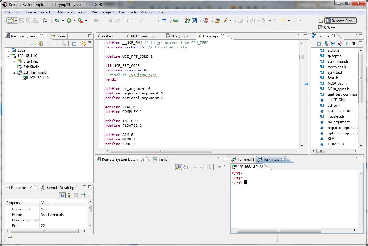
To gather some comparison data, we can switch to a RSE perspective and run the application directly from SDK using Linux commands.
Depending on how the options are set for your SDK installation, you may have a Remote System Explorer icon in the upper right corner of the SDK window. Click on that to get a RSE perspective. Otherwise, from the main menu bar select Window > Open Perspective > Other.
In the selection box, click Remote System Explorer and click OK
In the left pane, right click on Ssh Terminals and select Launch Terminal
A terminal for the ZC702 will be opened
Conclusions
If we run the fft-zynq application from RSE, we can see the execution time of the three different methods of running the FFT. These are the times for execution using the debug option (-g) set to 5 and the architecture option (-a) set to 0 for the ARM alone, 1 for the NEON SIMD engine and 2 for the hardware FFT. Since the hardware FFT is built only for 4096 point FFT, we use that as a comparison in all cases.
ARM alone - 940 usec
NEON SIMD engine - 682 usec
Hardware FFT - 129 usec
If a specific run is repeated several times, there is some variability in the reported execution times. For the ARM processor alone, the variability is the highest, likely because of the greater impact of Linux and the potential for cache misses. Because the NEON SIMD engine runs considerably quicker, the potential for Linux overhead is less, decreasing the variability. Because the hardware FFT is in hardware, there is very little difference in the reported execution times over different runs.
With an execution time improvement of over 5X of the hardware FFT over the NEON SIMD engine, this clearly demonstrates the power of the combination of processing and programmable logic in the Zynq-7000 AP SoC family of devices.
The addition of hardware to perform the FFT is simplified by the use of IP Integrator. This enables rapid addition of functionality to the overall Zynq-7000 AP AoC platform to enhance performance of critical portions of an application. With the addition of some simple address mapping and control passing, communications between software running on the PS and hardware in the PL can be easily achieved.
Expected Results
The comparison numbers above are for the 4096 FFT. For smaller FFTs, the time for either the ARM processor or the NEON SIMD engine will be proportionally less, and will approach that of the hardware FFT. However, if the hardware FFT were also reduced in size to those same parameters, the execution would also decrease. In a real application, the use of partial reconfiguration could be readily used to change the hardware FFT size to fit the requirements at hand.
Saving the workspace
For ease of completing subsequent Tech Tips that use the results of this Tech Tip, it is wise to save the workspace so it can be restored later as a known starting point. Because only the sw portion of the base TRD was modified, only that portion needs to be saved. If you choose to do this,
Select File -> Export or right click on the white space in the Project Explorer pane and select Export.
In the Export dialogue box expand General and select Archive File.
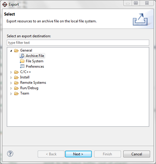
Click Next
The Export Archive File dialogue will appear
Click the Select All button to select the full workspace
Click the Browse button and navigate to where you want to save the workspace and then create an appropriate file in which to save the workspace. In our case, we are saving this to HWfft_workspace.zip
Be sure the save in zip format is selected unless you are on a Linux system in which case you might select the tar format.
Then click Finish
The workspace will be saved in the specified archive file for later use.
© Copyright 2019 - 2022 Xilinx Inc. Privacy Policy