Zynq UltraScale+ MPSoC Base TRD 2019.1
Table of Contents
Revision History
This wiki page complements the 2019.1 version of the Base TRD. For other versions, refer to the Zynq UltraScale+ MPSoC Base TRD overview page.Change Log:
- Update all projects, IPs, and tools versions to 2019.1
- Various fixes and improvements
Overview
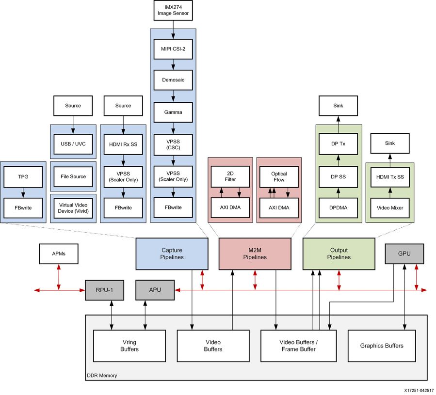
The Zynq UltraScale+ MPSoC Base Targeted Reference Design (TRD) is an embedded video processing application running on a combination of APU (SMP Linux), RPU (bare-metal) and PL. A high-level block diagram is shown below.
The design supports the following video interfaces:
The following processing accelerators are implemented as memory-to-memory pipelines in the PL (red):
The TRD demonstrates the value of offloading computation intensive tasks from the PS onto PL, thereby freeing APU resources. The APU load is plotted on the GUI to compare a pure software vs hardware accelerated implementation.
The RPU is used to monitor the live memory throughput of the design by reading the built-in AXI performance monitors (APM) inside the PS. The data is sent to the APU via the OpenAMP communication framework and plotted on the GUI.
This wiki contains information about:
Additional material that is not hosted on the wiki:
Required:
Optional:
The reference design has been tested successfully with the following user-supplied components.
Monitors:
HDMI Sources:
USB Webcams:
Note: The Logitech C525 webcam takes about 12 seconds to start after selection from the GUI. It will start streaming once the LED is lit.
DisplayPort Cables:
Storage Devices:
Required:
Steps to generate the license:
The reference design is split into 10 design modules DM1 to DM10:
Each module is described in more detail on the respective tutorial page (see below).
The following table shows the dependency matrix between different modules. For example: DM6 (row) depends on or builds on top of modules DM1 and DM5 (columns).
The top-level directory structure shows major design components. A pre-built SD card image is provide for DM10 along with a basic README and legal notice file.
The below table shows which design components are used in which design modules. A graphical view for each design module is provided on the respective design module tutorial page.
Required:
Optional:
- Sources (blue):
- Virtual video device (vivid) implemented purely in software
- USB webcam connected to the PS (optional)
- Test pattern generator (TPG) implemented in the PL
- HDMI Rx capture pipeline implemented in the PL
- MIPI CSI-2 Rx based image sensor pipeline implemented in PL + FMC
- File source (raw video only)
- Sinks (green):
- DP Tx display pipeline in the PS
- HDMI Tx display pipeline implemented in the PL
The following processing accelerators are implemented as memory-to-memory pipelines in the PL (red):
- 2D-Convolution filter with programmable coefficients
- Dense optical flow algorithm
The TRD demonstrates the value of offloading computation intensive tasks from the PS onto PL, thereby freeing APU resources. The APU load is plotted on the GUI to compare a pure software vs hardware accelerated implementation.
The RPU is used to monitor the live memory throughput of the design by reading the built-in AXI performance monitors (APM) inside the PS. The data is sent to the APU via the OpenAMP communication framework and plotted on the GUI.
This wiki contains information about:
- How to setup the ZCU102 evaluation board and run the reference design.
- How to build all the TRD components based on the provided source files via detailed step-by-step tutorials.
Additional material that is not hosted on the wiki:
- Zynq UltraScale+ MPSoC Base TRD user guide UG1221: contains information about system, software and hardware architecture.
Software Tools and System Requirements
Hardware
Required:
- ZCU102 evaluation board
- rev 1.0 or rev D2 with production silicon
- Monitor with DisplayPort or HDMI input supporting one of the following resolutions:
- 3840x2160 or
- 1920x1080 or
- 1280x720
- Display Port cable (DP certified) or HDMI cable
- Micro-USB cable, connected to laptop or desktop for the terminal emulator
- Xilinx USB3 micro-B adapter
- adapter shipped with ZCU102 rev 1.0 + production silicon
- adapter needs to be purchased separately for ZCU102 rev D2 with production silicon
- USB mouse
- SD card
Optional:
- HDMI video source with output supporting one of the following resolutions:
- 3840x2160 or
- 1920x1080 or
- 1280x720
- USB webcam
- USB 3.0 hub (supplied with ZCU102 kit)
- Leopard LI-IMX274MIPI-FMC (only supported on rev 1.0 boards)
Compatibility
The reference design has been tested successfully with the following user-supplied components.
Monitors:
| Make/Model | Native Resolution |
|---|---|
| Viewsonic VP2780-4K | 3840x2160 (60/30Hz) |
| Acer S277HK | 3840x2160 (60/30Hz) |
| LG 27UD58 | 3840x2160 (60/30Hz) |
| Dell U2718Q | 3840x2160 (60/30Hz) |
| Dell P2415Q | 3840x2160 (30Hz) |
| Dell U2414H | 1920x1080 (60Hz) |
| GeChic On-Lap1303H | 1920x1080 (60Hz) |
HDMI Sources:
| Make/Model | Resolutions |
|---|---|
| Nvidia Shield TV | 3840x2160, 1920x1080 |
| OTT TV BOX M8N | 3840x2160, 1920x1080, 1280x720 |
| Roku 2 XS | 1920x1080, 1280x720 |
| TVix Slim S1 Multimedia Player | 1920x1080, 1280x720 |
USB Webcams:
| Make/Model | Supported Resolutions | Supported Formats |
|---|---|---|
| Logitech BRIO | 1920x1080 (30fps) | YUYV |
| Logitech HD Pro Webcam C920 | 1920x1080 (5fps), 1280x720 (10fps) | YUYV |
| Logitech HD Webcam C525 | 1920x1080 (5fps), 1280x720 (10fps) | YUYV |
DisplayPort Cables:
- Cable Matters DisplayPort Cable-E342987
- Monster Advanced DisplayPort Cable-E194698
Storage Devices:
- Crucial BX200 2.5in SATA SSD 240GB
- San Disk UltraFit USB3.0 Flash Drive 16 GB
Software
Required:
- Linux host machine for all tool flow tutorials (see UG1144 for detailed OS requirements)
- SDSoC Development Environment version 2019.1 (see UG1238 for installation instructions)
- PetaLinux Tools version 2019.1 (see UG1144 for installation instructions)
- Git distributed version control system
- Silicon Labs quad CP210x USB-to-UART bridge driver
- Serial terminal emulator e.g. teraterm
- Reference Design Zip File for ZCU102 rev 1.0 or rev D2 / production silicon including all source code and project files.
Licensing
- Important: Certain material in this reference design is separately licensed by third parties and may be subject to the GNU General Public License version 2, the GNU Lesser General License version 2.1, or other licenses.
The Third Party Library Sources zip file provides a copy of separately licensed material that is not included in the reference design. - You will need only the SDSoC license to build the design which includes all the required IP licenses. You can evaluate for 60-days or purchase it here.
Steps to generate the license:
- Log in here with your work E-mail address (If you do not yet have an account, follow the steps under Create Account)
- Generate a license from “Create New Licenses” by checking "SDSoC Environment, 60 Day Evaluation License"
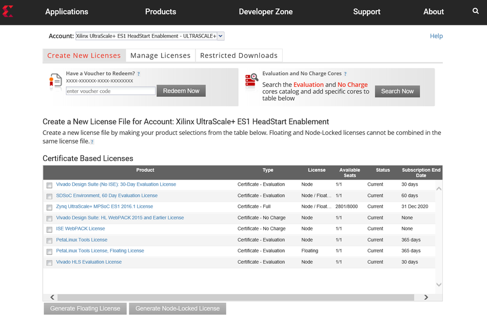
- Under system information, give the host details.
- Proceed until you get the license agreement and accept it.
- The License (.lic file) will be sent to the email-id mentioned in the login details.
- Copy the license file locally and give the same path in the SDSoC license manager.
Design Files
Design Modules
The reference design is split into 10 design modules DM1 to DM10:
- DM1 – APU SMP Linux
- DM2 – RPU0 FreeRTOS Application
- DM3 – RPU1 Bare-metal Application
- DM4 – APU/RPU1 Inter Process Communication
- DM5 – APU Qt Application
- DM6 – PL Video Capture
- DM7 – OpenCV-based Image Processing
- DM8 – PL-accelerated Image Processing
- DM9 – Two Image Processing Functions
- DM10 – Full-fledged Base TRD
Each module is described in more detail on the respective tutorial page (see below).
The following table shows the dependency matrix between different modules. For example: DM6 (row) depends on or builds on top of modules DM1 and DM5 (columns).
| DM1 | DM2 | DM3 | DM4 | DM5 | DM6 | DM7 | DM8 | DM9 | |
|---|---|---|---|---|---|---|---|---|---|
| DM1 | |||||||||
| DM2 | |||||||||
| DM3 | |||||||||
| DM4 | + | + | |||||||
| DM5 | + | ||||||||
| DM6 | + | + | |||||||
| DM7 | + | + | + | ||||||
| DM8 | + | + | + | + | |||||
| DM9 | + | + | + | + | + | ||||
| DM10 | + | + | + | + | + | + | + | + | + |
Design Components
The top-level directory structure shows major design components. A pre-built SD card image is provide for DM10 along with a basic README and legal notice file.
rdf0421-zcu102-base-trd-2019-1/
├── IMPORTANT_NOTICE_CONCERNING_THIRD_PARTY_CONTENT.txt
├── petalinux
│   ├── sdk.sh
│   └── zcu102-prod-base-dm10.bsp
├── README.txt
├── sd_card
│   └── dm10
│       ├── BOOT.BIN
│       ├── image.ub
│       ├── libgstsdxfilter2d.so
│       ├── libgstsdxopticalflow.so
│       └── perfapm-server.elf
├── workspaces
│   ├── ws_heartbeat
│   │   ├── heartbeat
│   │   ├── heartbeat_bsp
│   │   └── hw_platform_0
│   ├── ws_perfapm-ctl
│   │   ├── hw_platform_0
│   │   ├── perfapm
│   │   ├── perfapm_bsp
│   │   └── perfapm-ctl
│   └── ws_perfapm-server
│       ├── hw_platform_0
│       ├── perfapm
│       ├── perfapm_bsp
│       └── perfapm-server
└── zcu102_base_trd
    ├── hw
    │   └── zcu102_base_trd.dsa
    ├── samples
    │   ├── gstsdxfilter2d
    │   └── gstsdxopticalflow
    ├── sw
    │   ├── a53_linux
    │   ├── prebuilt
    │   └── zcu102_base_trd.spfm
    └── zcu102_base_trd.xpfm
| Design Component | Design Module | |||||||||
|---|---|---|---|---|---|---|---|---|---|---|
| DM1 | DM2 | DM3 | DM4 | DM5 | DM6 | DM7 | DM8 | DM9 | DM10 | |
| heartbeat | Y | Y | ||||||||
| perfapm-ctl | Y | |||||||||
| perfapm-server | Y | Y | ||||||||
| perfapm-client | Y | |||||||||
| video-qt2 | Y | Y | Y | Y | Y | Y | ||||
| gstsdxfilter2d | Y | Y | Y | Y | ||||||
| gstsdxopticalflow | Y | Y | ||||||||
Tutorials
Board Setup
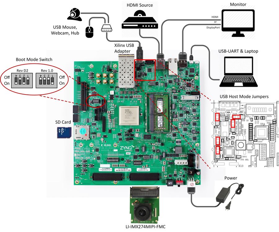
Required:
- Connect power supply to 12V power connector.
- Connect USB mouse via USB hub to the USB3 micro-AB connector.
- Display
- Connect a DisplayPort cable to DisplayPort connector on the board; connect the other end to a monitor OR
- Connect an HDMI cable to HDMI Tx connector (top) on the board; connect the other end to a monitor
Note: Make sure you only connect either DP or HDMI Tx on the board, not both, otherwise the design might malfunction - Connect micro-USB cable to the USB-UART connector; use the following settings for your terminal emulator:
- Baud Rate: 115200
- Data: 8 bit
- Parity: None
- Stop: 1 bit
- Flow Control: None
- Insert SD card (FAT formatted) with binaries copied from
$TRD_HOME/images/dm10directory.
Optional:
- Connect a USB webcam to the USB hub.
Note: The USB webcam needs to output YUYV pixel format. Other formats are not supported in this design. - Connect an HDMI cable to HDMI Rx connector (bottom) on the board; connect the other end to an HDMI source
- Connect the LI-IMX274MIPI-FMC module to the HPC0 FMC connector on the board
Note: The design only supports this FMC on rev 1.0 boards. Vadj needs to be set to 1.2V for correct operation of the daughter card. If the FMC card does not seem functional, please follow the instructions explained in Answer Record AR67308 to check and/or set Vadj.
Jumpers & Switches:
- Set boot mode to SD card:
- Rev 1.0: SW6[4:1] - off,off,off, on
- Rev D2: SW6[4:1] - on, off on, off
- Configure USB jumpers for host mode
- J110: 2-3
- J109: 1-2
- J112: 2-3
- J7: 1-2
- J113: 1-2
Build and Run Flow
To run the pre-built SD card image for design module 10, follow the instructions here.
The following tutorials assume that the
$TRD_HOME environment variable has been set as below.% export TRD_HOME=</path/to/downloaded/zip-file>/rdf0421-zcu102-base-trd-2019-1
For the individual tutorials, follow the links below:
- DM1 Tutorial – APU SMP Linux
- DM2 Tutorial – RPU0 FreeRTOS Application
- DM3 Tutorial – RPU1 Bare-metal Application
- DM4 Tutorial – APU/RPU1 Inter Process Communication
- DM5 Tutorial – APU Qt Application
- DM6 Tutorial – PL Video Capture
- DM7 Tutorial – OpenCV-based Image Processing
- DM8 Tutorial – PL-accelerated Image Processing
- DM9 Tutorial – Two Image Processing Functions
- DM10 Tutorial – Full-fledged Base TRD
Other Information
Known Issues
- There is a GLIB memory leak when switching modes in the GUI if an accelerator is part of the pipeline and set to HW mode.
- Frequency: Common
- Workaround: Already implemented in the 2018.3 release (by setting environment variable
G_SLICE=always-mallocbefore executing video_qt2 application)
- Application crashes after popping out "Failed to allocate required memory" dialog box if you connect a HDMI-rx input-source which is in sleep mode .
- Frequency: Intermittent
- Workaround: Power-cycle your HDMI-rx input (for e.g. Nvidia Shield TV) to make it out-of-sleep. Kill the BaseTRD application from the linux prompt and re-run again.
Limitations
- SDSoC accelerator code runs very slow in pure software implementation when Debug configuration is used. For faster execution, set project build configuration to Release which sets SDSoC compiler to optimize most (-O3).
- Accelerator frame rate drops if HDMI Tx 4K60 is selected. The Filter2d frame rate maxes out at 4K 30 fps and the optical flow frame rate maxes out at 4K 35 fps.
- The application only supports the following display resolutions: 3840x2160, 1920x1080 and 1280x720.
- The application does not support audio.
- USB webcams:
- Need to support the YUYV pixel format.
- Most webcams don't support resolutions > 1080p using uncompressed video. Make sure you start the GUI in 1080p or 720p mode using the -r switch if you want to use your webcam as video source.
- For USB2 webcams, it is expected to see increased latency and low frame rate.
- Do not connect a DisplayPort cable and HDMI Tx at the same time.
- Make sure the DisplayPort or HDMI Tx cable is plugged in when you power on the board.
- DP-to-HDMI adapters are not supported, see AR 67462
- HDMI Rx:
- Does not support YUV 4:2:0 input.
- Does not support HDCP encrypted input.
- Does not support hotplug or dynamic resolution changes while the application is running.
- Leopard LI-IMX274MIPI-FMC:
- The Leopard IMX274 MIPI FMC is only supported on rev 1.0 boards and will not work on rev D2 boards.
- SDSoC does not support “Estimate Performance” for the xfopenCV library and in general for all the C++ templates (the part of Performance Estimation flow not yet supported is the estimate of software performance for function templates). Once the HLS estimate of HW resources pops up, the Ethernet P2P communication process between the SDSoC GUI and the board stalls forever and no error message is displayed.
- Harmless warning message on the serial console for DM1-9 designs : "Failed to open rpmsg file /dev/rpmsg0.: No such file or directory"
- Sometimes you might get a blank screen on HDMI monitors when you power-on zcu102. As a workaround, try power-cycling your HDMI monitor
- CPU idle and frequency scaling have been disabled in the kernel bootargs according to SDSoC guidelines (see UG1146, pg 46) and to enable debug with xsdb (see AR69143).
Support
To obtain technical support for this reference design, go to the:
- Xilinx Answers Database to locate answers to known issues
- Xilinx Community Forums to ask questions or discuss technical details and issues. Please make sure to browse the existing topics first before filing a new topic. If you do file a new topic, make sure it is filed in the sub-forum that best describes your issue or question e.g. Embedded Linux for any Linux related questions. Please include "ZCU102 Base TRD" and the release version in the topic name along with a brief summary of the issue.
© Copyright 2019 - 2022 Xilinx Inc. Privacy Policy