Zynq UltraScale+MPSoC VCU TRD 2019.2 - Xilinx Low Latency PL DDR XV20 SDI Video Capture and Display
Table of Contents
1 Overview
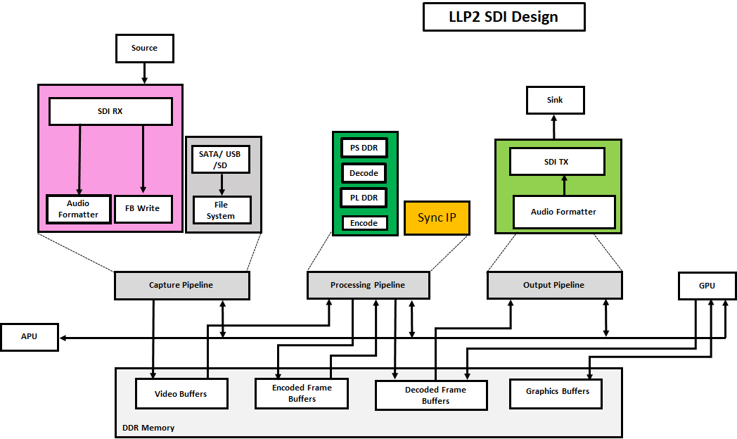
This module enables the capture of video from an SDI Rx subsystem implemented in the PL. The video can be displayed through the SDI Tx subsystem implemented in the PL. The module can stream-out and stream-in live captured video frames through an Ethernet interface at ultra-low latencies using Sync IP. This module supports multi-stream for XV20 pixel format. In this design, PL_DDR is used for decoding and PS_DDR for encoding so that DDR bandwidth would be enough to support high bandwidth VCU applications requiring simultaneous encoder and decoder operations and transcoding at 4k @60 FPS.
The VCU encoder and decoder operate in slice mode. An input frame is divided into multiple slices (8 or 16) horizontally. The encoder generates a slice_done interrupt at every end of the slice. Generated NAL unit data can be passed to a downstream element immediately without waiting for the frame_done interrupt. The VCU decoder also starts processing data as soon as one slice of data is ready in its circular buffer instead of waiting for complete frame data. The Sync IP does an AXI transaction-level tracking so that the producer and consumer can be synchronized at the granularity of AXI transactions instead of granularity at the video buffer level. Sync IP is responsible for synchronizing buffers between Capture DMA and VCU encoder as both works on the same buffer.
The capture element (FB write DMA) writes video buffers in raster-scan order. SyncIP monitors the buffer level while the capture element is writing into DRAM and allows the encoder to read input buffer data if the requested data is already written by DMA, otherwise it blocks the encoder until DMA completes its writes. On the decoder side, the VCU decoder writes decoded video buffer data into DRAM in block-raster scan order and displays reads data in raster-scan order. To avoid display under-run problems, the software ensures a phase difference of "~frame_period/2", so that decoder is ahead compared to display.
This design supports the following video interfaces:
Sources:
- SDI-Rx capture pipeline implemented in the PL.
- Stream-In from network or internet.
Sinks:
- SDI-Tx display pipeline implemented in the PL.
VCU Codec:
- Video Encode/Decode capability using VCU hard block in PL.
- AVC/HEVC encoding
- Encoder/decoder parameter configuration.
Video format:
- XV20
Supported Resolution:
The table below provides the supported resolution from command line app only in this design.
| Resolution | Command Line | |
| Single Stream | Multi-stream | |
| 4kp60 | √ | NA |
| 4kp30 | √ | NA |
| 1080p60 | √ | NA |
√ - Supported
NA – Not applicable
x – Not supported
The below table gives information about the features supported in this design.
| Pipeline | Input source | Format | Output Type | Resolution | VCU codec |
|---|---|---|---|---|---|
Capture--> Encode--> Decode--> Display | SDI-Rx | XV20 | SDI-Tx | 4kp60/4kp30/1080p60 | HEVC/AVC |
Stream-Out pipeline | SDI-Rx | XV20 | Stream-Out | 4kp60/4kp30/1080p60 | HEVC/AVC |
Stream-in pipeline | Stream-In | XV20 | SDI-Tx | 4kp60/4kp30/1080p60 | HEVC/AVC |
The below figure shows the PL DDR SDI design hardware block diagram.
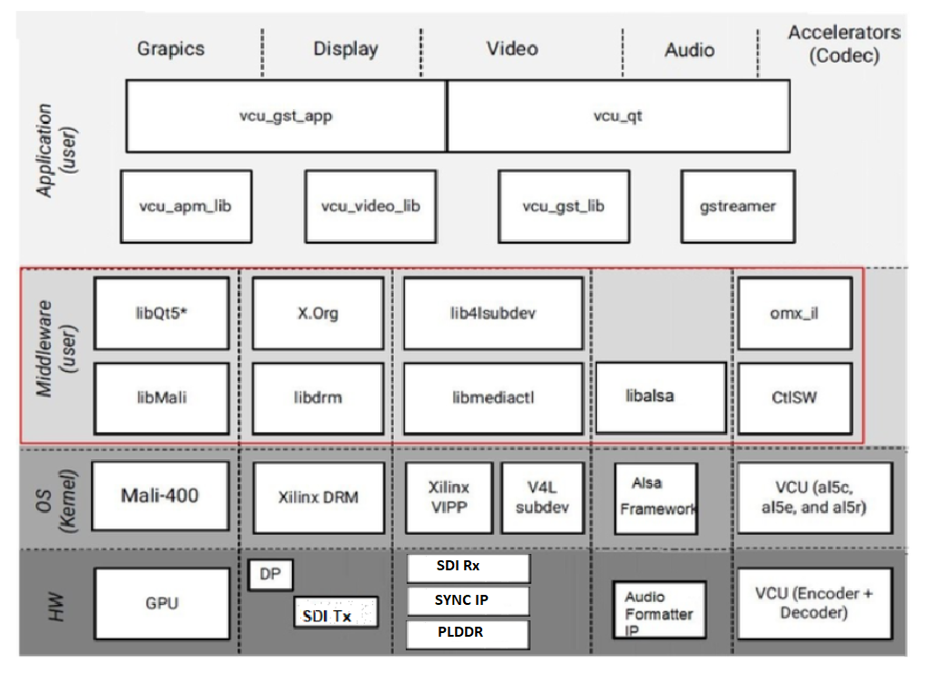
The below figure shows the PL DDR SDI design software block diagram.
1.1 Board Setup
Refer below link for Board Setup
1.2 Run Flow
The TRD package is released with the source code, Vivado project, Petalinux BSP, and SD card image that enables the user to run the demonstration. It also includes the binaries necessary to configure and boot the ZCU106 board. Prior to running the steps mentioned in this wiki page, download the TRD package and extract its contents to a directory referred to as ‘TRD_HOME' which is the home directory.
Refer below link to download all TRD contents.
TRD package contents are placed in the following directory structure. The user needs to copy all the files from the $TRD_HOME/images/vcu_llp2_sdi_xv20 to FAT32 formatted SD card directory.
rdf0428-zcu106-vcu-trd-2019-2
├── apu
│   └── vcu_petalinux_bsp
│   └── xilinx-vcu-zcu106-v2019.2-final.bsp
├── images
│   ├── vcu_llp2_sdi_xv20
│   │   ├── autostart.sh
│   │   ├── bin
│   │   ├── BOOT.BIN
│   │   ├── config
│   │   ├── image.ub
│   │   ├── system.dtb
│   │   └── vcu
├── pl
│   ├── constrs
│   │   ├── hdmi_plddr.xdc
│   │   ├── misc.xdc
│   │   ├── sdi_interclk.xdc
│   │   ├── vcu_10g.xdc
│   │   ├── vcu_audio_async.xdc
│   │   ├── vcu_audio_w10.xdc
│   │   ├── vcu_audio.xdc
│   │   ├── vcu_hdmirx.xdc
│   │   ├── vcu_hdmitx.xdc
│   │   ├── vcu_pcie.xdc
│   │   ├── vcu_sdirx_place.xdc
│   │   ├── vcu_sdirx_timing.xdc
│   │   ├── vcu_sdirxtx_place.xdc
│   │   ├── vcu_sdirxtx_plddr_place.xdc
│   │   ├── vcu_sdirxtx_plddr_timing.xdc
│   │   ├── vcu_sdirxtx_timing.xdc
│   │   ├── vcu_sditx_async.xdc
│   │   ├── vcu_sditx_place.xdc
│   │   ├── vcu_sditx_timing.xdc
│   │   ├── vcu_trd_async.xdc
│   │   ├── vcu_trd.xdc
│   │   ├── vcu_uc2_async.xdc
│   │   └── vcu_uc2.xdc
│   ├── designs
│   │   ├── zcu106_llp2_sdi
│   ├── prebuild
│   │   ├── zcu106_llp2_sdi
│   └── srcs
│   ├── hdl
│   └── ip
└── README.txt
configuration files(input.cfg) for various resolutions are placed in the following directory structure in /media/card.
config/
├── 1080p60
│   ├── Display
│   │   ├── Single_1080p60_AVC_25Mbps.cfg
│   │   └── Single_1080p60_HEVC_25Mbps.cfg
│   ├── Stream-in
│   │   ├── Single_1080p60_AVC_25Mbps.sh
│   │   └── Single_1080p60_HEVC_25Mbps.sh
│   └── Stream-out
│       ├── Single_1080p60_AVC_25Mbps.cfg
│       ├── Single_1080p60_AVC_25Mbps.sh
│       ├── Single_1080p60_HEVC_25Mbps.cfg
│       └── Single_1080p60_HEVC_25Mbps.sh
├── 4kp30
│   ├── Display
│   │   ├── Single_4kp30_AVC_25Mbps.cfg
│   │   └── Single_4kp30_HEVC_25Mbps.cfg
│   ├── Stream-in
│   │   ├── Single_4kp30_AVC_25Mbps.sh
│   │   └── Single_4kp30_HEVC_25Mbps.sh
│   └── Stream-out
│       ├── Single_4kp30_AVC_25Mbps.cfg
│       ├── Single_4kp30_AVC_25Mbps.sh
│       ├── Single_4kp30_HEVC_25Mbps.cfg
│       └── Single_4kp30_HEVC_25Mbps.sh
└── 4kp60
    ├── Display
    │   ├── Single_4kp60_AVC_25Mbps.cfg
    │   └── Single_4kp60_HEVC_25Mbps.cfg
    ├── Stream-in
    │   ├── Single_4kp60_AVC_25Mbps.sh
    │   └── Single_4kp60_HEVC_25Mbps.sh
    └── Stream-out
        ├── Single_4kp60_AVC_25Mbps.cfg
        ├── Single_4kp60_AVC_25Mbps.sh
        ├── Single_4kp60_HEVC_25Mbps.cfg
        └── Single_4kp60_HEVC_25Mbps.sh
1.2.1 GStreamer Application (vcu_gst_app)
The vcu_gst_app is a command-line multi-threaded Linux application. The command-line application requires an input configuration file (.cfg) to be provided in the plain text.
Run below modetest command to set CRTC configurations for 4kp60:
% xmodetest -M xlnx -s 31:3840x2160-60@XV20 -w 31:sdi_mode:5 -w 31:sdi_data_stream:8 -w 31:is_frac:0
Run below modetest command to set CRTC configurations for 4kp30:
% xmodetest -M xlnx -s 31:3840x2160-60@XV20 -w 31:sdi_mode:4 -w 31:sdi_data_stream:8 -w 31:is_frac:0
Execution of the application is shown below:
% vcu_gst_app < path to *.cfg file>
Example:
4kp60 XV20 HEVC_25Mbps Display Pipeline execution.
% vcu_gst_app /media/card/config/4kp60/Display/Single_4kp60_HEVC_25Mbps.cfg
4kp60 XV20 HEVC_25Mbps low-delay-p Stream-out Pipeline execution.
% vcu_gst_app /media/card/config/4kp60/Stream-out/Single_4kp60_HEVC_25Mbps.cfg
4kp60 XV20 HEVC_HIGH Stream-in Pipeline execution
% sh /media/card/config/4kp60/Stream-in/Single_4kp60_HEVC_25Mbps.sh
NOTE: Make sure SDI-Rx should be configured to 4kp60 mode.
To measure the latency of the pipeline, run the below command. The latency data is huge, so dump it to a file.
% GST_DEBUG="GST_TRACER:7" GST_TRACERS="latency" GST_DEBUG_FILE=/media/card/latency_log.log vcu_gst_app /media/card/config/4kp60/Display/Single_4kp60_HEVC_25Mbps.cfg
Refer below link for detailed run flow steps
1.3 Build Flow
Refer below link for detailed build flow steps
2 Other Information
2.1 Known Issues
- For VCU related known issues please refer AR# 72293: PetaLinux 2019.1 - Product Update Release Notes and Known Issues.
- Design has a negative slack of WNS around -50 ps . However it does not affect the functionality of the design in the long run also and will be fixed in next release.
2.2 Limitations
- For VCU related limitations please refer AR# 72293: PetaLinux 2019.1 - Product Update Release Notes and Known Issues and PG252 link.
2.3 Optimum VCU Encoder parameters for use-cases
Video streaming:
- Video streaming use-case requires very stable bitrate graph for all pictures.
- It is good to avoid periodic large Intra pictures during the encoding session
- Low-latency rate control (hardware RC) is the preferred control-rate for video streaming, it tries to maintain equal amount frame sizes for all pictures.
- Good to avoid periodic Intra frames instead use low-delay-p (IPPPPP…)
- VBR is not a preferred mode of streaming.
Performance: AVC Encoder settings:
- It is preferred to use 8 or higher slices for better AVC encoder performance.
- AVC standard does not support Tile mode processing which results in the processing of MB rows sequentially for entropy coding.
Quality: Low bitrate AVC encoding:
- Enable profile=high and use qp-mode=auto for low-bitrate encoding use-cases.
- The high profile enables 8x8 transform which results in better video quality at low bitrates.
3 Appendix A - Input Configuration File (input.cfg)
The example configuration files are stored at /media/card/config/ folder.
Common Configuration:
It is the starting point of common configuration.
Num of Input:
1
Output:
Select the video interface.
Options: SDI
Out Type:
Options: display and stream
Display Rate:
Pipeline frame rate.
Options: 30 FPS or 60 FPS for each stream.
Exit:
It indicates to the application that the configuration is over.
Input Configuration:
It is the starting point of the input configuration.
Input Num:
Starting Nth input configuration.
Options: 1
Input Type:
Input source type.
Options: SDI
Raw:
To tell the pipeline is processed or pass-through.
Options: False
Note: Raw use-case is not supported
Width:
The width of the live source.
Options: 3840, 1920
Height:
The height of the live source.
Options: 2160, 1080
Format:
The format of input data.
Options: XV20
Enable LLP2:
To enable LLP2 use-case.
Options: True
Exit:
It indicates to the application that the configuration is over.
Encoder Configuration:
It is the starting point of encoder configuration.
Encoder Num:
Starting Nth encoder configuration.
Options: 1, 2
Encoder Name:
Name of the encoder.
Options: AVC, HEVC
Profile:
Name of the profile.
Options: high for AVC and main for HEVC.
Rate Control:
Rate control options.
Options: low_latency.
Filler Data:
Filler Data NAL units for CBR rate control.
Options: False
QP:
QP control mode used by the VCU encoder.
Options: Uniform, Auto
L2 Cache:
Enable or Disable L2Cache buffer in encoding process.
Options: True, False
Latency Mode:
Encoder latency mode.
Options: sub_frame
Low Bandwidth:
If enabled, decrease the vertical search range used for P-frame motion estimation to reduce the bandwidth.
Options: True, False
Gop Mode:
Group of Pictures mode.
Options: Basic, low_delay_p, low_delay_b
Bitrate:
Target bitrate in Kbps
Options: 1-25000
B Frames:
Number of B-frames between two consecutive P-frames
Options: 0
Slice:
The number of slices produced for each frame. Each slice contains one or more complete macroblock/CTU row(s). Slices are distributed over the frame as regularly as possible. If slice-size is defined as well more slices may be produced to fit the slice-size requirement.
Options:
4-22 4kp resolution with HEVC codec
4-32 4kp resolution with AVC codec
4-32 1080p resolution with HEVC codec
4-32 1080p resolution with AVC codec
Note: The recommended is 8 for LLP2 use-case.
GoP Length:
The distance between two consecutive I frames
Options: 1-1000
Preset:
Options: Custom
Exit
It indicates to the application that the configuration is over.
Streaming Configuration:
It is the starting point of streaming configuration.
Streaming Num:
Starting Nth Streaming configuration.
Options: 1
Host IP:
The host to send the packets to
Options: 192.168.25.89 or Windows PC IP
Port:
The port to send the packets to
Options: 5004, 5008, 5012 and 5016
Exit
It indicates to the application that the configuration is over.
Trace Configuration:
It is the starting point of trace configuration.
FPS Info:
To display fps info on the console.
Options: True, False
APM Info:
To display APM counter number on the console.
Options: True, False
Pipeline Info:
To display pipeline info on console.
Options: True, False
Exit
It indicates to the application that the configuration is over.
4 Appendix B
- SDI source can be locked to any resolution. Run the below command for all media nodes to print media device topology where "mediaX" represents different media nodes. In the topology, log look for the “v_smpte_uhdsdi_rx_ss” string to identify the SDI input source media node.
$ xmedia-ctl -p -d /dev/mediaX
- To check the link status, resolution and video node of the SDI input source, run below xmedia-ctl command where "mediaX" indicates media node for the SDI input source.
# xmedia-ctl -d /dev/media0 -p
Media controller API version 4.19.0

Media device information
------------------------
driver          xilinx-video
model           Xilinx Video Composite Device
serial
bus info
hw revision     0x0
driver version  4.19.0

Device topology
- entity 1: vcap_sdirx output 0 (1 pad, 1 link)
            type Node subtype V4L flags 0
            device node name /dev/video0
        pad0: Sink
                <- "a0030000.v_smpte_uhdsdi_rx_ss":0 [ENABLED]

- entity 5: a0030000.v_smpte_uhdsdi_rx_ss (1 pad, 1 link)
            type V4L2 subdev subtype Unknown flags 0
            device node name /dev/v4l-subdev0
        pad0: Source
                [fmt:UYVY10_1X20/3840x2160@1000/60000 field:none]
                [dv.detect:BT.656/1120 3840x2160p60 (4400x2250) stds:CEA-861 flags:can-reduce-fps,CE-video,0x80]   --> RX link up
                -> "vcap_sdirx output 0":0 [ENABLED]
When SDI source is connected to 4KP60 resolution, it shows:
NOTE: Check resolution and frame-rate of "dv.detect" under "v_smpte_uhdsdi_rx_ss" node.
When the SDI source is not connected, it shows:
# xmedia-ctl -d /dev/media0 -p -----> media node for SDI input source
Media controller API version 4.19.0

Media device information
--[ 1215.787801] xilinx-sdirxss a0030000.v_smpte_uhdsdi_rx_ss: Video not locked!
----------------------
driver          xilinx-video
model           Xilinx Video Composite Device
serial
bus info
hw revision     0x0
driver version  4.19.0

Device topology
- entity 1: vcap_sdirx output 0 (1 pad, 1 link)
            type Node subtype V4L flags 0
            device node name /dev/video0
        pad0: Sink
                <- "a0030000.v_smpte_uhdsdi_rx_ss":0 [ENABLED]

- entity 5: a0030000.v_smpte_uhdsdi_rx_ss (1 pad, 1 link)
            type V4L2 subdev subtype Unknown flags 0
            device node name /dev/v4l-subdev0
        pad0: Source
                [dv.query:no-lock]                           ----------------> link is not detected
                -> "vcap_sdirx output 0":0 [ENABLED]
NOTE: Here "dv.query:no-link" under "v_smpte_uhdsdi_rx_ss" node shows SDI-Rx source is not connected or SDI-Rx source is not active(Try waking up the device by pressing a key on remote).
- Follow the below steps to switch the SDI-Rx resolution from 1080p60 to 4kp60.
- Check current SDI Input Source Resolution (1080p60) by following the above-mentioned steps.
- Run vcu_gst_app for current SDI resolution (1080p60) by executing the following command.
$ vcu_gst_app /media/card/config/input.cfg
Below configurations needs to be set in input.cfg for SDI-1080p60.
CHANGE ME


Common Configuration    : START
Num Of Input            : 1
Output                  : SDI
Out Type                : Display
Frame Rate              : 60
Exit

Input Configuration     : START
Input Num               : 1
Input Type              : SDI
Raw                     : TRUE0-
Width                   : 1920
Height                  : 1080
Format                  : XV20
Enable LLP2             : TRUE
Exit
- Change Resolution of SDI Input Source from 1080p60 to 4kp60 by following below steps.
- Set the SDI source resolution to 4kp60 (Homepage → Settings → Display & Sound → Resolution → change to 4kp60).
- Save the configuration to take place the change.
- Verify the desired SDI Input Source Resolution (4kp60) by following the above-mentioned steps.
- Change Resolution of SDI Input Source from 1080p60 to 4kp60 by following below steps.
- If SDI Tx link-up issue is observed after Linux booting, use the following command to get the TPG screen on SDI-Tx.
% xmodetest -M xlnx -s 31:3840x2160-60@XV20 -w 31:sdi_mode:5 -w 31:sdi_data_stream:8 -w 31:is_frac:0
- SDI LLP2 4kp60 Modetest command
- The table below lists the parameters of the pixel format.
NOTE: After booting you need to run the modetest command(mandatory) for respective resolution you want to validate.
| Pixel Format | GStreamer Format | Media Bus Format | GStreamer HEVC Profile | GStreamer AVC Profile | Kmssink Plane-id |
|---|---|---|---|---|---|
| XV20 | NV16_10LE32 | UYVY10_1X20 | main-422-10 | high-4:2:2 | 30 and 31 |
- Run the following gst-launch-1.0 command to display XV20 video on SDI-Tx using low-latency GStreamer pipeline (capture → encode → decode → display). Where "video0" indicates a video node for the input source.
$gst-launch-1.0 v4l2src io-mode=4 device=/dev/video0 ! video/x-raw\(memory:XLNXLL\), width=3840, height=2160, format=NV16_10LE32, framerate=60/1 ! omxh265enc qp-mode=auto gop-mode=basic gop-length=60 b-frames=0 target-bitrate=25000 num-slices=8 control-rate=low-latency prefetch-buffer=TRUE low-bandwidth=false filler-data=0 cpb-size=1000 initial-delay=500 ! video/x-h265, alignment=nal ! queue max-size-buffers=0 ! omxh265dec low-latency=1 ! video/x-raw\(memory:XLNXLL\) ! queue max-size-bytes=0 ! fpsdisplaysink name=fpssink text-overlay=false video-sink="kmssink driver-name=xlnx max-lateness=5000000 show-preroll-frame=false sync=true" sync=true -v
- Run the following gst-launch-1.0 command to stream-out XV20 video using low-latency GStreamer pipeline. Where "video0" indicates a video node for the input source.
$ gst-launch-1.0 v4l2src io-mode=4 device=/dev/video0 ! video/x-raw\(memory:XLNXLL\), width=3840, height=2160, format=NV16_10LE32, framerate=60/1 ! omxh264enc qp-mode=auto gop-mode=low-delay-p gop-length=60 periodicity-idr=60 b-frames=0 target-bitrate=25000 num-slices=8 control-rate=low-latency prefetch-buffer=TRUE low-bandwidth=false filler-data=0 cpb-size=1000 initial-delay=500 ! video/x-h264, alignment=nal ! queue max-size-buffers=0 ! rtph264pay ! udpsink host=192.168.25.89 port=5004 buffer-size=60000000 max-bitrate=120000000 max-lateness=-1 qos-dscp=60 async=false
NOTE: Here 192.168.25.89 is host/client IP address and 5004 is port no.
- Run the following gst-launch-1.0 command to display XV20 stream-in video on SDI-Tx using low-latency GStreamer pipeline where 5004 is port no.
$ gst-launch-1.0 udpsrc port=5004 buffer-size=60000000 caps="application/x-rtp, media=video, clock-rate=90000, payload=96, encoding-name=H264" ! queue ! rtph264depay ! h264parse ! video/x-h264, alignment=nal ! omxh264dec low-latency=1 ! video/x-raw\(memory:XLNXLL\) ! queue max-size-bytes=0 ! fpsdisplaysink name=fpssink text-overlay=false video-sink="kmssink driver-name=xlnx" sync=true -v
© Copyright 2019 - 2022 Xilinx Inc. Privacy Policy