Zynq UltraScale+ MPSoC VCU TRD 2019.2 - Run and Build Flow
Table of Contents
1 Overview
The below sections describe the detailed run and build steps for all the TRD components. For the overview, software tools, system requirements, design files, and board setup follow the link below:
2 Run Flow
- Set up the board as explained in “Board Setup” Section in link Zynq UltraScale+ MPSoC VCU TRD 2019.2
- Prepare the SD card. Use the SD Card Formatter tool to format the SD card, https://www.sdcard.org/downloads/formatter_4/

Please note that the Windows format option can't be used.
- Copy all the files from the $TRD_HOME/images/<Path to Design Images>/ to FAT32 formatted SD card directory
- Power on the board; make sure INIT_B, DONE and all power rail LEDs are lit green
- After a successful boot, you may proceed with either GUI based application(Section 2.1) or command-line based GStreamer application(Section 2.2)
NOTE 1: The AR-69368 should be applied and rebuild the SD boot images for HighSD card.
NOTE 2: The SD card file system is mounted at /media/card. Optional storage medium SATA and USB are mounted at /media/sata and /media/usb respectively.
2.1 Graphic User Interface
A QT based graphical user interface (GUI) provides control and monitoring interface. GUI will run on DP only.
NOTE1: Qt GUI will work on for VCU TRD Multi-stream design and HDMI Video Capture and HDMI Display with the Audio design.
NOTE2: Make sure the monitor is in DP mode when you run the QT GUI app.
Run the below command to launch GUI on Display port when connected.
% run_vcu.sh
The GUI is not supported in HDMI Tx. In HDMI 4kp60 mode, GUI requires an additional ~2GB memory bandwidth. If you invoke the GUI cause memory bandwidth issue. So HDMI Tx, use only command line application (vcu_gst_app). The table below provides the supported display interfaces for both GUI and command-line applications.
| Display Interface | GUI | Command Line Application |
| DisplayPort | √ | √ |
| HDMI | Not supported | √ |
The figure below shows the home screen of the GUI when only DP is connected.
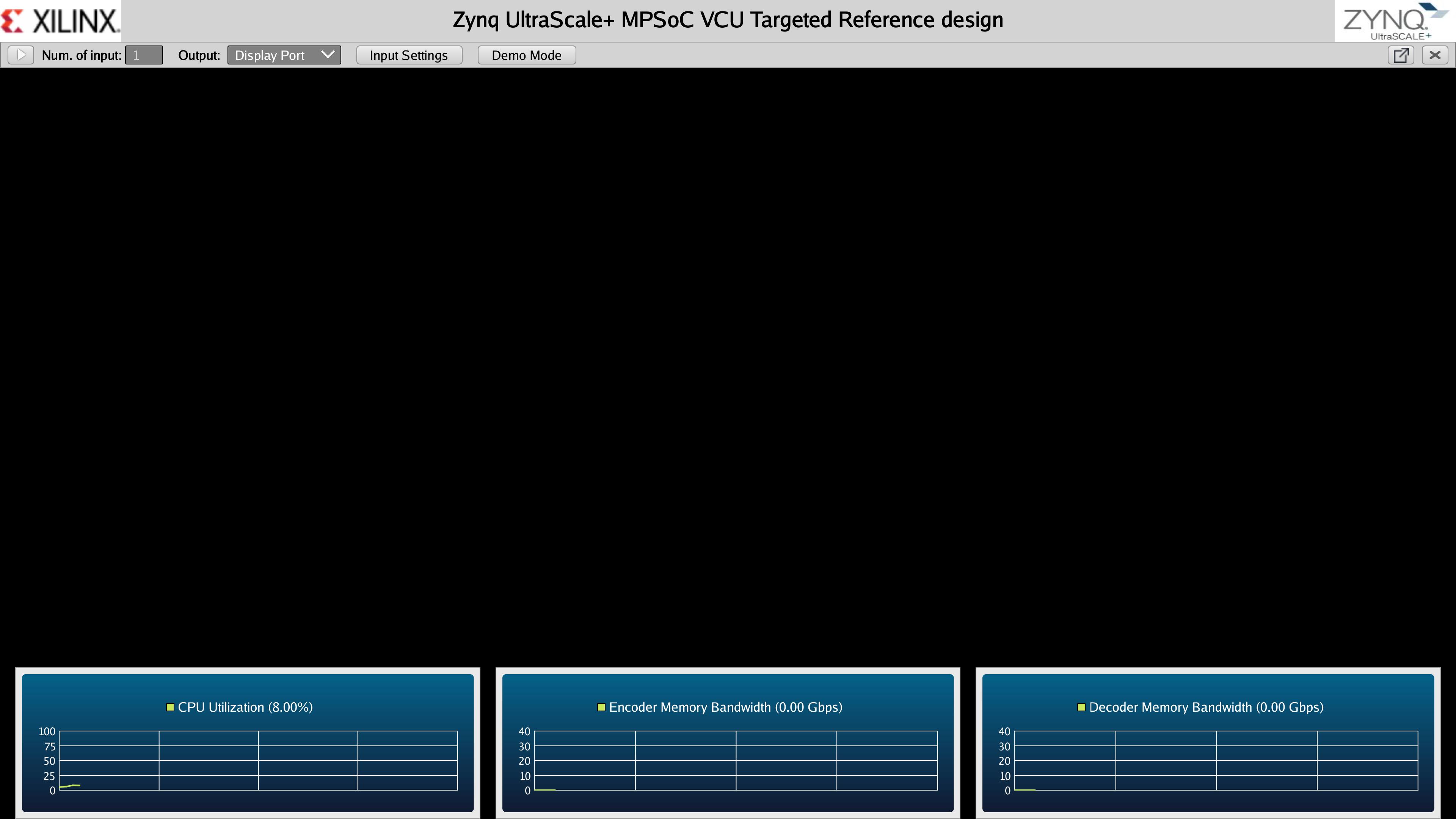
GUI only supports single-stream playback. Supported resolutions are 1080p and 4kp. The supported frame rate for 1080p is 60 fps and 30fps for 4kp. For all multi-stream use cases and 4kp60 single stream, the user has to run command-line applications.
Qt GUI has the following options for the user to select:
Number of Input
This determines the number of active video sources. Only one input source is supported.
Output
This option allows the user to select a sink for the pipeline. Supported output sink types are display port, record, and stream. For the Display Port, the available Codec options are either enc-dec or Pass-through. For Record and Stream Out, the available Codec option is Enc.
Demo Mode
- By clicking this button, the button text state changes to stop and the user can play all pipelines(TPG, MIPI, HDMI) with raw and presets configurations.
- For every 10 seconds, playback preset changes and it plays in a loop till the user clicks on the stop button.
- If no source connected it displays an error popup.
- If any error returns in any playback, it skips and continues to play other pipelines.
- With HDMI Video Capture and HDMI Display with Audio design, To enable audio in a demo mode goto→ Input Settings→ select Input1: HDMI→ Settings→ Audio Settings→ Enable Audio → true and Click on Demo Mode
Input Settings
The below figure shows the input settings window with configuration options.

Different configuration options available in the QT pop up window are:
Input Source (Input 1)
The following video sources (4K) are available as part of input video selection:
- HDMI-Rx: To select the HDMI Rx source as input.
- File: To select a file source as input.
- Test Pattern Generator (TPG): To select TPG source as input.
- MIPI: To select MIPI Camera source as input.
- Stream-In: To select a streaming pipeline.
Codec
The following options are available as part of Codec functionality
- Enc-Dec: This option is to select encode and decode in the pipeline.
- Enc: This option is to select encode only in the pipeline for record or stream out a use case.
- Pass-through: This option is to display raw video.
Preset
There are six predefined presets. If the user edits any control options preset mode switches to “Custom”.
- AVC Low Encoder type = H264, bitrate = 10Mbps
- AVC Medium Encoder type = H264, bitrate = 30Mbps
- AVC High Encoder type = H264, bitrate = 60Mbps
- HEVC Low Encoder type = H265, bitrate = 10Mbps
- HEVC Medium Encoder type = H265, bitrate = 30Mbps
- HEVC High Encoder type = H265, bitrate = 60Mbps
Profile = Main, Rate Control = CBR, Filler Data = true, QP = Auto, L2 Cache = true, Latency mode = Normal, Low Bandwidth = false, Gop Mode = Basic, B-frame = 0, Slice = 8 and GoP Length = 60 common for all above options.
- Custom User-specific options
Please refer to the Supported Encoder Format section for the supported encoder format in this release.
SCD
Enable or Disable SCD in the pipeline
Settings
A user can control the encoder, record and stream out configuration from the GUI, Settings option is enabled when the pipeline is in the stop state. The user can control the encoder parameters when output option is selected as Display port/Record/Stream.
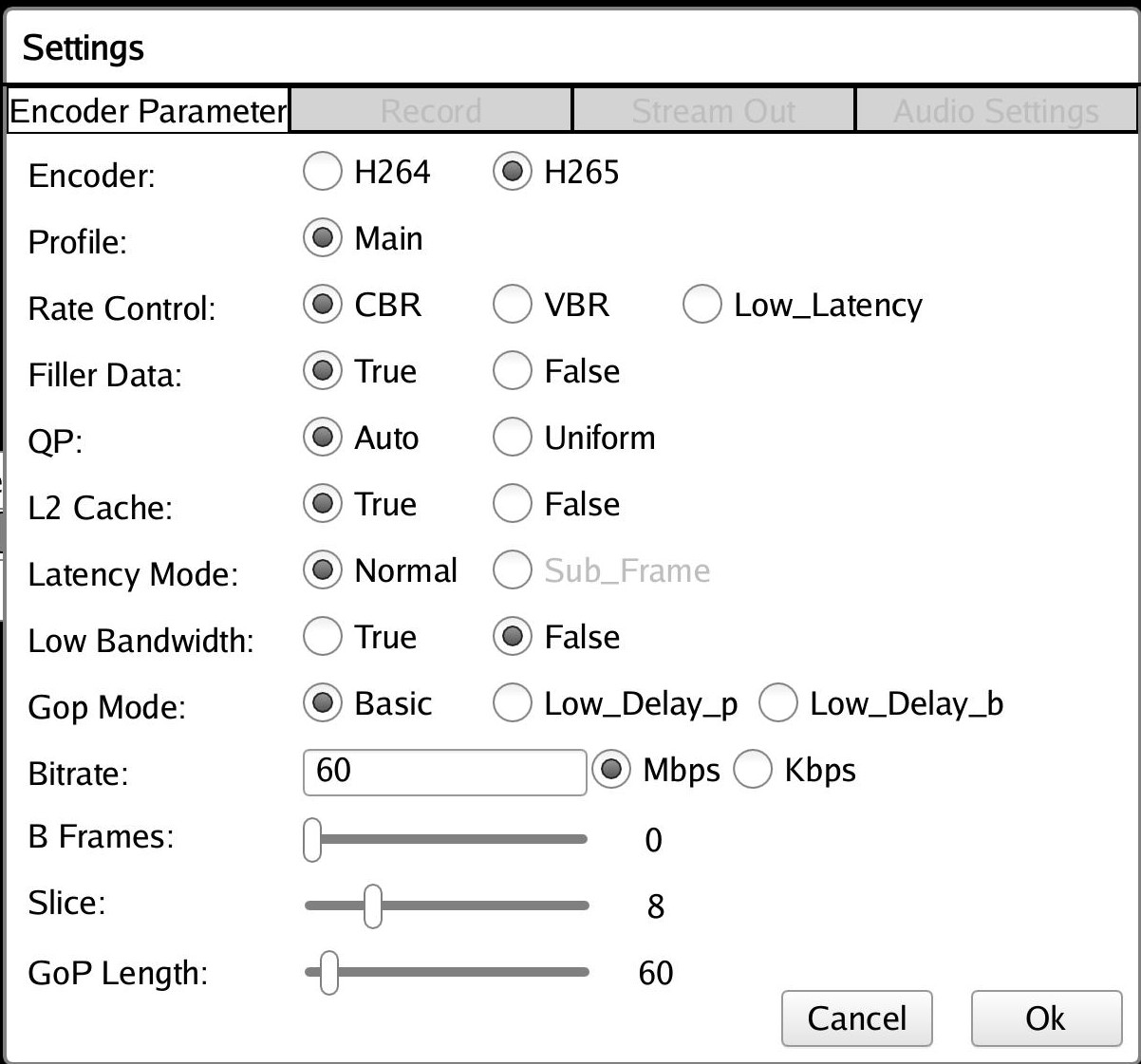
Encoder
This can be either H264 or H265.
Profile
The standard defines a set of capabilities, which are referred to as profiles, targeting specific classes of applications. These are declared as a profile code (profile_idc) and a set of constraints applied in the encoder. This allows a decoder to recognize the requirements to decode that specific stream.
H264 supports baseline, main and high profile. In H265 only the main profile is supported.
QP
Quantization in an encoder is controlled by a quantization parameter. It specifies how to generate the QP per coding unit (CU). Two modes are supported-
- Uniform: All CUs of the slice using the same QP
- Auto: VCU encoder changes the QP for each coding unit according to its content.
Rate Control
Constant bitrate (CBR), variable bitrate (VBR) and low-latency are supported. CBR mode generates a constant bit rate that you can predefine. CBR is recommended for limited bandwidth use cases.
Bitrate
Encoding bit rate. In digital multimedia, bit rate often refers to the number of bits used per unit of playback time to represent a continuous medium such as audio or video after source coding (data compression).
B-frame
Short for bi-directional frame, or bi-directional predictive frame, a video compression method used by the MPEG standard. It ranges from 0 to 4.
Slice
The number of slices produced for each frame. Each slice contains one or more complete macroblock/CTU row(s). Slices are distributed over the frame as regularly as possible. If slice-size is defined as well more slices may be produced to fit the slice-size requirement
Range:
4-22 4kp resolution with HEVC codec
4-32 4kp resolution with AVC codec
4-32 1080p resolution with HEVC codec
4-32 1080p resolution with AVC codec
GoP Length
In video coding, a group of pictures, or GOP structure, specifies the order in which intra and inter-frames are arranged. And GOP-length is a length between two Intra frames. The GOP is a collection of successive pictures within a coded video stream. Each coded video stream consists of successive GOPs, from which the visible frames are generated. Its range is from 1 to 1000.
Filler Data
Filler Data NAL units for CBR rate control to maintain constant bitrate throughout the playback. It can be enabled or disabled. It is applicable to CBR mode only.
L2 Cache
Enable or Disable L2Cache buffer in the encoding process.
Latency Mode
Encoder latency mode. It can be normal or sub_frame mode.
Low Bandwidth
If enabled, decrease the vertical search range used for P-frame motion estimation to reduce the bandwidth.
Gop Mode
Group of Pictures mode. It can be Basic, low_delay_p, or low_delay_b.
Record
When the Output option is selected as Record, A tab will be enabled in settings window through which a user can record the video into the storage medium.
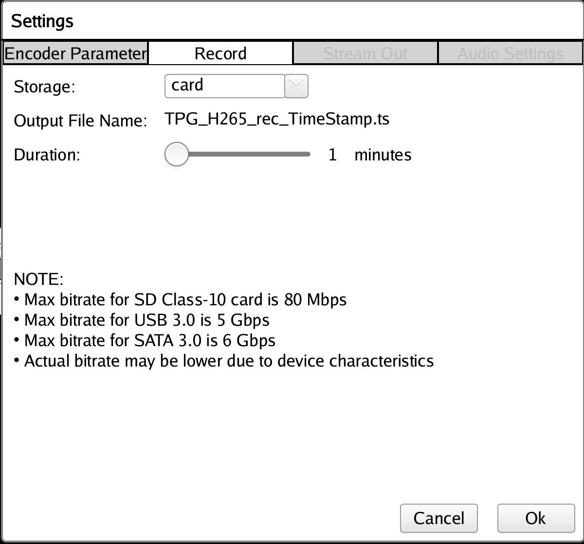
Storage
This option specifies a storage device for the recorded file. The list is dynamically populated based on mounted storage devices. Supported storage devices are SD, USB, and SATA.
Output File Name
Name of the output file. For H264, recorded file get saved as <Source name>_H264_rec_<timestamp>.ts and for H265 it will be <Source name>_H265_rec_<timestamp>.ts
Duration
This option will specify the Recording time duration. It ranges from 1-3 mins.
NOTE: Due to speed and storage constraints it is recommended to use USB/SATA storage devices for the record.
Stream-out
The stream-out panel allows the user to configure streaming parameters.
Stream-out Prerequisites when zcu106 board is connected to host machine:
- Host server machine (with GPU) capable of playing 4K60 stream.
- Setup an Ethernet connection between the ZCU106 board and the host machine. Ensure the connection is alive by doing a ping from the board to the host machine.
- VLC player installed on the host machine.
- A firewall is turned off on the host machine.
- Start a VLC player on the host before streaming from GUI.
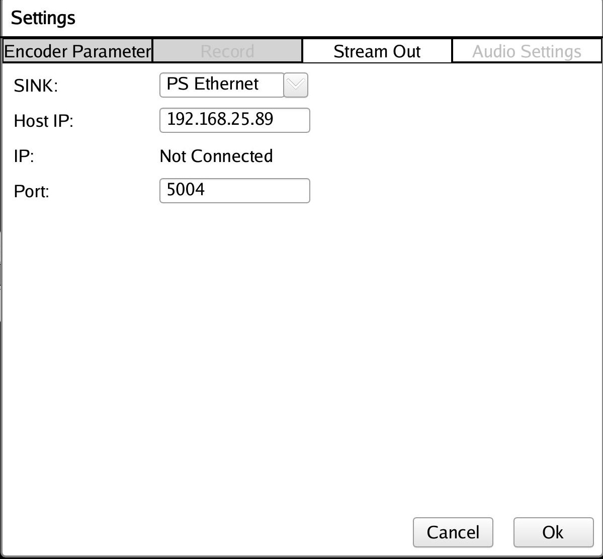
Sink
Provides sink option for the stream-out. It is set to PS Ethernet.
Host IP
The IP address of a computer or other Zynq® UltraScale+™ MPSoC board in which streaming video will be played on. It is set to 192.168.25.89 by default.
IP
This option will show the IP address of the board if the Ethernet link is up. If no Ethernet link is connected then it will show “Not Connected”.
Port
Port number of the Ethernet link. By default, it is set to 5004.
Steps for Stream Out
Here are the steps to get the ZCU106 TRD to play out to VLC:
- Make sure that your machine can play 4Kp60 streams and turned off the Firewall.
- Connect your PC to the ZCU106 board. It is recommended to a direct connection between the ZCU106 board and PC to minimize the network traffic.
- Set the IP address for the ZCU106 board and PC to use the same subnet (i.e. ZCU106 - ifconfig eth0 192.168.25.90 and PC - 192.168.25.89).
- Launch VLC on your PC and Click on media -> Open Network Stream and Enter Network URL (rtp://192.168.25.89:5004, rtp://@:5004) and click on Play.
- Setup output option to “Stream” in the ZCU106 VCU TRD GUI.
- Configure the Stream out settings and make sure that the ZCU106 VCU TRD GUI is pointing to the IP address of your PC.
- Select the HDMI-Rx/MIPI or the TPG as an input.
- Press play in VLC on your PC. (The Client must start first, but VLC times out if you wait too long before starting the ZCU106 VCU TRD Stream).
- Press play on the ZCU106 VCU TRD GUI
Audio Settings
The Audio Settings panel allows the user to configure audio parameters.
Note: The Audio Settings are only applicable in-case of HDMI Video Capture and HDMI Display with Audio design.
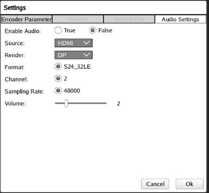
The format of the audio. It is set to S24_32LE by default.
The number of audio channels. It is set to 2 by default.
To set the volume level. It is set to 2.0 by default.
% devmem 0XFD4AC000 32 0xffffffff
Stream-In
Stream-In panel allows the user to enter a network URL.
Stream-In Prerequisites when 2 ZCU106 boards are connected:
- Setup an Ethernet connection between 2 ZCU106 boards. Ensure the connection is alive by doing a ping from one board to another board.
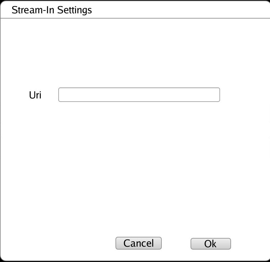
Uri
It provides the network URL to receive the network stream. As an e.g. “udp://192.168.25.89:5004/”.
Steps for Stream Out from one board and Stream In from another board
- Connect the ZCU106 board to another ZCU106 board. It is recommended a direct connection between 2 ZCU106 boards to minimize the network traffic.
- Set the IP address for both ZCU106 board such that both boards are in the same subnet (i.e. ZCU106 1st board - ifconfig eth0 192.168.25.90, ZCU106 2nd board - ifconfig eth0 192.168.25.89).
- Make sure both boards are connected by ping command.
- Setup output option to “Stream” in the 1st ZCU106 board from VCU TRD GUI.
- Configure the Stream out settings in the 1st ZCU106 board from VCU TRD GUI and make sure that it is pointing to the IP address (192.168.25.89) of the 2nd board.
- Setup an input option to “Stream In” in the 2nd ZCU106 board from VCU TRD GUI.
- Enter the network URL (udp://192.168.25.89:5004/) in Stream In settings in the 2nd ZCU106 board from VCU TRD GUI
- Press play on both the ZCU106 board from VCU TRD GUI.
NOTE: It is recommended to use rev-1.0 or rev-F board.
2.2 GStreamer Application (vcu_gst_app)
The vcu_gst_app is a command-line multi-threaded Linux application that uses the vcu_gst_lib interface similar to vcu_qt. The command-line application requires an input configuration file (input.cfg) to be provided in the plain text. Refer to the Appendix A - Input Configuration File (input.cfg) for the file format and description.
Before the execution of vcu_gst_app, we need to check the HDMI-Rx or SDI-Rx link status depending on the design. Refer to Appendix B for HDMI-Rx and SDI-Rx link status.
Before the execution of vcu_gst_app, we need to check the HDMI-Tx link and CRTC configurations depending on the design. Refer to Appendix B for the HDMI-Tx link up the issue.
Execution of the application is shown below:
% vcu_gst_app <path to *.cfg file>
Note: Required Storage medium SATA and USB are mounted at /media/sata and /media/usb respectively.
Example:
4kp60 HEVC_HIGH Display Pipeline execution
% vcu_gst_app /media/card/config/1-4kp60/Display/Single_4kp60_HEVC_HIGH.cfg
4kp60 HEVC_HIGH Record Pipeline execution
% vcu_gst_app /media/card/config/1-4kp60/Record/Single_4kp60_HEVC_HIGH.cfg
4kp60 HEVC_HIGH Stream-out Pipeline execution
% vcu_gst_app /media/card/config/1-4kp60/Stream-out/Single_4kp60_HEVC_HIGH.cfg
4kp60 HEVC_HIGH Stream-in Pipeline execution
% vcu_gst_app /media/card/config/1-4kp60/Stream-in/input.cfg
NOTE: Make sure HDMI-Rx should be configured to 4kp60 mode.
To measure the latency of the pipeline, run the below command. The latency data is huge, so dump it to a file.
% GST_DEBUG="GST_TRACER:7" GST_TRACERS="latency" GST_DEBUG_FILE=/run/latency.log vcu_gst_app /media/card/config/input.cfg
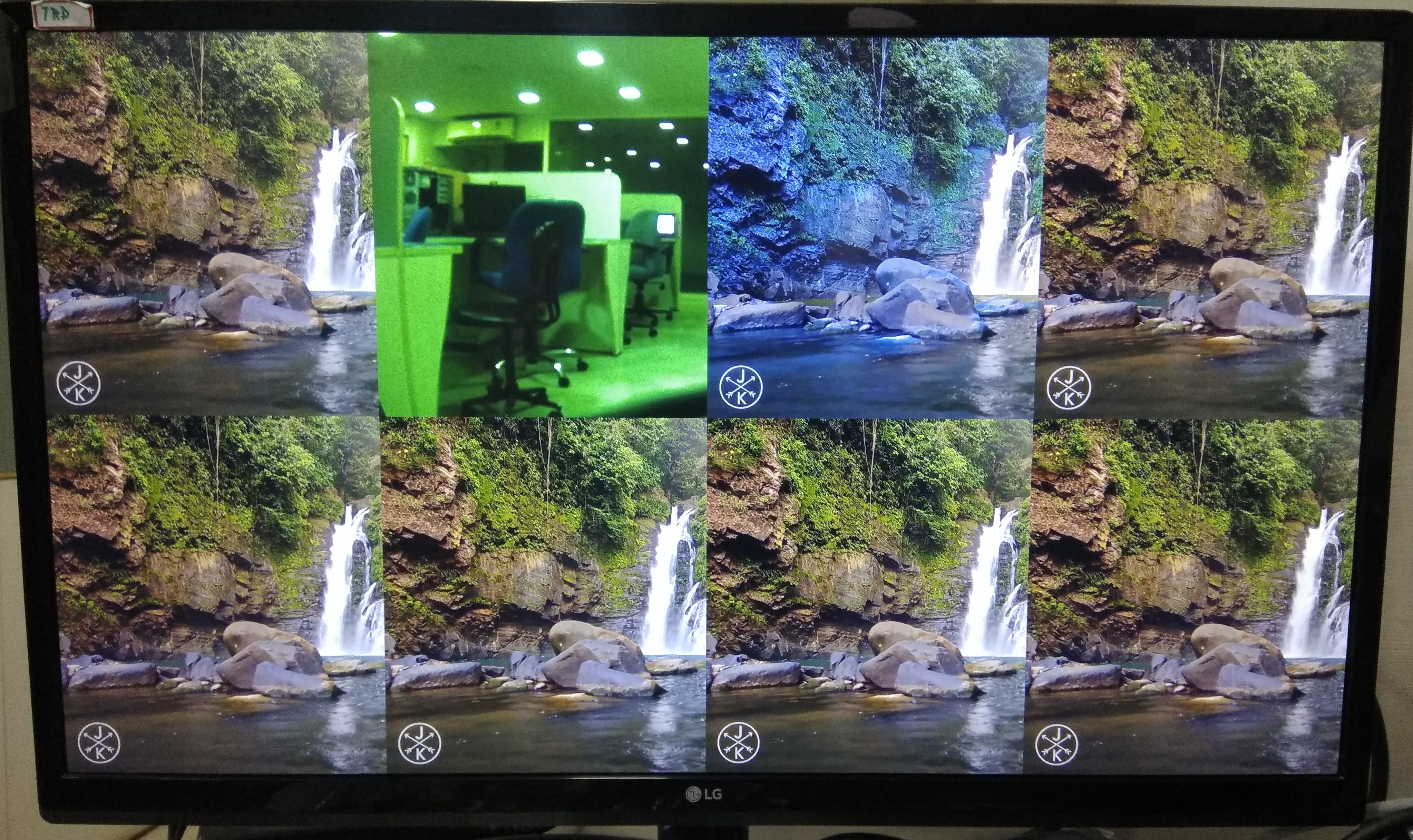
2.2.1 Multistream
When the number of input is more than one in the command line application, it is a multi-stream use case. The command-line application supports multi-streaming, multi-recording, or multi-display. The input source type can be HDMI, TPG and MIPI. The table below lists the multi-stream features supported in various designs.
| Design | Input Source | Format | Resolution |
| Full-fledged VCU TRD | HDMI-Rx, MIPI, TPG | NV12 | 4kp60, 2-4kp30, 4-1080p60, 8-1080p30 |
| PL DDR HDMI Video Capture and HDMI Display | HDMI-Rx | XV20 | 4kp60, 2-4kp30, 4-1080p60 |
| Xilinx Low Latency PS DDR NV12 HDMI Video Capture and HDMI Display | HDMI-Rx | NV12 | 4kp60, 2-4kp30, 2-1080p60 |
| Xilinx Low Latency PL DDR NV16 HDMI Video Capture and HDMI Display | HDMI-Rx | NV16 | 4kp60, 2-4kp30, 2-1080p60 |
| Xilinx Low Latency PL DDR XV20 HDMI Video Capture and HDMI Display | HDMI-Rx | XV20 | 4kp60, 2-4kp30, 2-1080p60 |
| Multi-Stream Audio Design | HDMI-Rx, MIPI | NV12 | 4kp60, 2-4kp30, 2-1080p60 |
Ex:
2-4kp30 HEVC_MEDIUM Display Pipeline execution
% vcu_gst_app /media/card/config/2-4kp30/Display/2_4kp30_HEVC_MEDIUM.cfg
NOTE: Make sure HDMI-Rx is configured to 4kp30 mode.
4-1080p60 HEVC_15Mbps Display Pipeline execution
% vcu_gst_app /media/card/config/4-1080p60/Display/4_1080p60_HEVC_15Mbps.cfg
NOTE: Make sure HDMI-Rx is configured to 1920x1080p60 mode.
8-1080p30 HEVC_7.5Mbps Display Pipeline execution
% vcu_gst_app /media/card/config/8-1080p30/Display/8_1080p30_HEVC_7_5Mbps.cfg
NOTE: Make sure HDMI-Rx is configured to 1920x1080p30 mode.
2.2.2 Streaming
Streaming Prerequisites when 2 ZCU106 boards are connected
- Setup an Ethernet connection between 2 ZCU106 boards. Ensure the connection is alive by doing a ping from one board to another board.
Steps for Streaming
- Connect the ZCU106 board to another ZCU106 board. It is recommended a direct connection between 2 ZCU106 boards to minimize the network traffic.
- Set the IP address for both ZCU106 board such that both boards are in the same subnet (i.e. ZCU106 1st board - ifconfig eth0 192.168.25.90, ZCU106 2nd board - ifconfig eth0 192.168.25.89).
- Make sure both boards are connected by ping command.
- Configure the Stream out (server) settings in input.cfg for the 1st board and make sure that it is pointing to the IP address of 2nd board (client) and Run vcu_gst_app for Stream out (server) pipeline.
% vcu_gst_app < path to stream out config file >
- Configure the Stream in (client) settings in input.cfg for 2nd board and Run vcu_gst_app for Stream in (client) pipeline.
% vcu_gst_app < path to stream in config file >
Streaming Prerequisites when ZCU106 board is connected to host machine:
- A host machine (with GPU) capable of playing 4K60 stream.
- Setup an Ethernet connection between the ZCU106 board and the host machine. Ensure the connection is alive by doing a ping from the board to the host machine.
- VLC player installed on the host machine.
- A firewall is turned off on the host machine.
- Start VLC player on the host before streaming.
Steps for Streaming
- Make sure that your machine can play 4Kp60/4Kp30 streams and turned off the Firewall.
- Connect your PC to the ZCU106 board. It is recommended to a direct connection between the ZCU106 board and PC to minimize the network traffic.
- Set the IP address for the ZCU106 board and PC to use the same subnet (i.e. ZCU106 - ifconfig eth0 192.168.25.90 and PC - 192.168.25.89).
- Make sure the ZCU106 board and host machine are connected by ping command.
- Launch VLC on your PC and Click on media -> Open Network Stream and Enter Network URL (rtp://192.168.25.89:5004, rtp://@:5004) and click on Play.
- Configure the Stream out (server) settings in input.cfg in the ZCU106 board and make sure that it is pointing to the IP address of the host machine (client) and Run vcu_gst_app for Stream out (server) pipeline.
% vcu_gst_app < path to stream out config file >
- Press the VLC player play button on your PC. (The Client must start first, but VLC times out if you wait too long before starting the ZCU106 TRD Stream).
NOTE: It is recommended to use rev-1.0 or rev-F board.
3 Build Flow
The following tutorials assume that the $TRD_HOME environment variable is set as given below.
% export TRD_HOME=</path/to/downloaded/zipfile>/rdf0428-zcu106-vcu-trd-2019-2
3.1 Hardware Design
Refer to the Vivado Design Suite User Guide: Using the Vivado IDE, UG893, for setting up the Vivado environment.
On Linux:
- Open a Linux terminal
- Change directory to $TRD_HOME/pl
- Run the following command in Vivado shell to create the Vivado IPI project and invoke the GUI.
% vivado -source designs/<hardware design name>/project.tcl
The table below lists the available hardware designs and the script used to generate a hardware project. These can be found in the scripts folder in a package under "pl/designs".
| Design | Project | hardware design name |
| VCU TRD | VCU TRD | zcu106_trd |
| Multistream Audio | HDMI-Rx + VCU + HDMI-Tx + Audio and MIPI-Rx + VCU+HDMI-TX + Audio - [ I2S-Rx + I2s-Tx ] | zc106_audio |
| SDI Capture and Display with Audio | SDI-Rx + VCU + SDI-Tx + Audio + PLDDR | zcu106_llp2_sdi |
| PL DDR HDMI Capture and Display | HDMI-Rx + VCU + HDMI-Tx + PL DDR | zcu106_plddr_hdmi |
| VCU PCIe | VCU PCIe | zcu106_pcie |
| VCU 10g | VCU 10g | zcu106_10g |
| HDMI Capture | HDMI Rx + VCU | zcu106_hdmirx |
| HDMI Display | VCU + HDMI Tx | zcu106_hdmitx |
| SDI Capture | SDI Rx + VCU | zcu106_sdirx |
| SDI Display | VCU + SDI Tx | zcu106_sditx |
| Xilinx Low Latency PS DDR NV12 HDMI Capture and Display | HDMI-Rx + VCU + HDMI-Tx + Sync IP | zcu106_llp2_nv12 |
| Xilinx Low Latency PL DDR NV16 HDMI Capture and Display | HDMI-Rx + VCU + HDMI-Tx + PL DDR + Sync IP | zcu106_llp2_nv16 |
| Xilinx Low Latency PL DDR XV20 HDMI Capture and Display | HDMI-Rx + VCU + HDMI-Tx + PL DDR + Sync IP | zcu106_llp2_xv20 |
| Xilinx Low Latency PL DDR XV20 SDI Capture and Display | SDI-Rx + VCU + SDI-Tx + Audio + PLDDR + Sync IP | zcu106_llp2_sdi |
Select tcl script as mentioned in the above table for different hardware designs as e.g use below command for Full-Fledged VCU TRD hardware design.
% vivado -source designs/zcu106_trd/project.tcl
After executing the script, the Vivado IPI block design comes up as shown in the below figure.
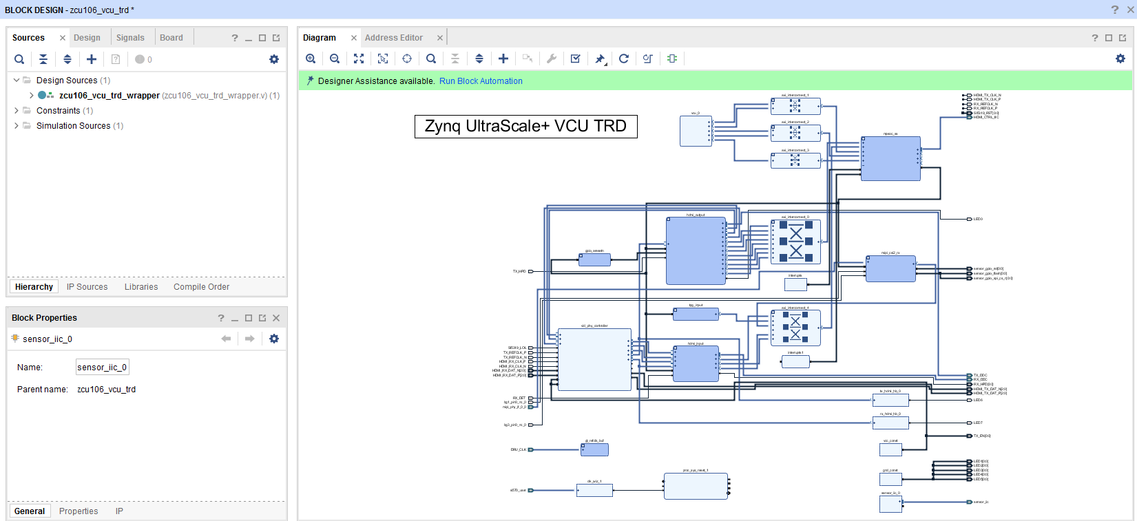
- Click on “Generate Bitstream”.
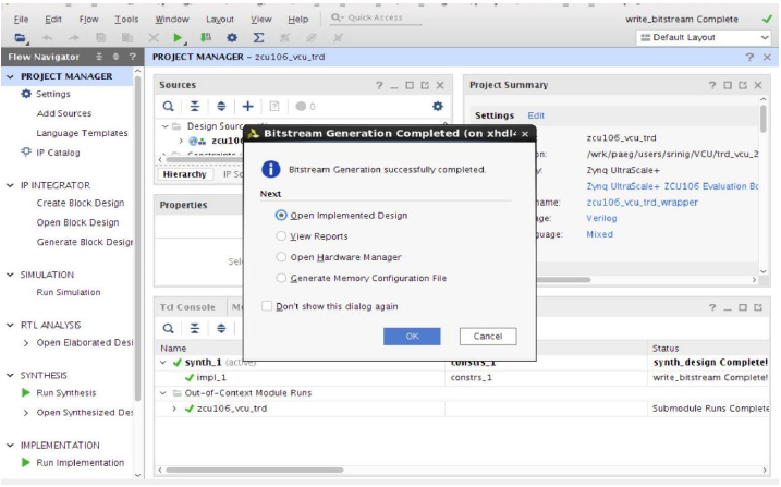
Note: If the user gets any pop-up with “No implementation Results available”. Click “Yes”. Then, if any pop-up comes up with “Launch runs”, Click "OK”.
The design is implemented and a pop-up window comes up saying “Open Implemented Design”. Click "OK".
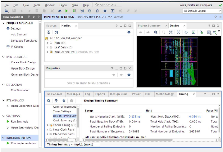
After opening the implemented design, the window looks as shown in the below figure.
Note: The actual results might graphically look different than the image shown
- Go to File > Export > Export Hardware
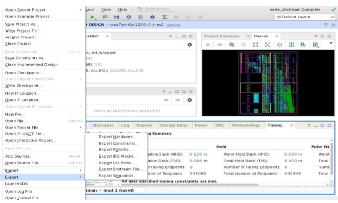
- In the Export Hardware Platform for SDK window select "Include bitstream" and click "OK".

By default, the XSA is created at $TRD_HOME/pl/build/<hardware design name>/<hardware design name_wrapper.xsa>. As an e.g the XSA is created at $TRD_HOME/pl/build/zcu106_trd/zcu106_trd_wrapper.xsa for VCU TRD hardware design.
3.2 VCU PetaLinux BSP
This tutorial shows how to build the Linux image and boot image using the PetaLinux build tool.
PetaLinux Installation: Refer to the PetaLinux Tools Documentation (UG1144) for installation.
NOTE: It is recommended to follow the build steps in sequence.
% source <path/to/petalinux-installer>/tool/petalinux-v2019.2-final/settings.sh
% echo $PETALINUX
Post PetaLinux installation $PETALINUX environment variable should be set
- Create a PetaLinux project.
% cd $TRD_HOME/apu/vcu_petalinux_bsp
% petalinux-create -t project -s xilinx-vcu-zcu106-v2019.2-final.bsp
- Configure the PetaLinux project.
% cd xilinx-vcu-zcu106-v2019.2-final
% petalinux-config --get-hw-description=<Path to prebuilt XSA>
The table below lists the available hardware designs and XSA path. These can be found in the prebuild folder in the package under "pl/prebuild".
| Design | Project | XSA file |
| VCU TRD | VCU TRD | zcu106_trd.xsa |
| Multistream Audio | HDMI-Rx + VCU + HDMI-Tx + Audio and MIPI-Rx + VCU + HDMI-TX + Audio - [ I2S-Rx + I2s-Tx ] | zcu106_audio.xsa |
| 10G Ethernet Video streaming | 10G HDMI-Rx + VCU + HDMI-Tx | zcu106_10g.xsa |
| SDI Capture and Display with Audio | SDI-Rx + VCU + SDI-Tx + Audio + PLDDR | zcu106_plddr_sdi.xsa |
| HDMI Video Capture | HDMI-Rx + VCU | zcu106_hdmirx.xsa |
| HDMI Video Display | VCU + HDMI-Tx | zcu106_hdmitx.xsa |
| SDI Video Capture | SDI-Rx + VCU | zcu106_sdirx.xsa |
| SDI Video Display | VCU + SDI-Tx | zcu106_sditx.xsa |
| PL DDR HDMI Capture and Display | HDMI-Rx + VCU + HDMI-Tx + PL DDR | zcu106_plddr_hdmi.xsa |
| PCIe Encode, Decode and Transcode | PCIe XDMA + VCU | zcu106_pcie.xsa |
Xilinx Low Latency PS DDR NV12 HDMI Capture and Display | HDMI-Rx + VCU + HDMI-Tx + Sync IP | zcu106_llp2_nv12.xsa |
| Xilinx Low Latency PL DDR NV16 HDMI Capture and Display | HDMI-Rx + VCU + HDMI-Tx + PL DDR + Sync IP | zcu106_llp2_nv16.xsa |
| Xilinx Low Latency PL DDR XV20 HDMI Capture and Display | HDMI-Rx + VCU + HDMI-Tx + PL DDR + Sync IP | zcu106_llp2_xv20.xsa |
| Xilinx Low Latency PL DDR XV20 SDI Capture and Display | SDI-Rx + VCU + SDI-Tx + PLDDR + SYNC IP | zcu106_llp2_sdi.xsa |
As an e.g use below command to configure the PetaLinux project for VCU TRD multi-stream design.
% petalinux-config --get-hw-description=$TRD_HOME/pl/prebuild/zcu106_trd
NOTE:
- If the Vivado project is modified, the user is expected to configure the bsp with the modified .xsa file and build.
% petalinux-config --get-hw-description=<Path to modified .xsa file>
- As an e.g If Vivado project is modified for VCU TRD multi-stream design then use below command to configure the bsp
% petalinux-config --get-hw-description=$TRD_HOME/pl/zcu106_trd/
- Create a soft link of design dtsi file to system-user.dtsi using below command
% cd project-spec/meta-user/recipes-bsp/device-tree/files/
% ln -sf <dtsi file name as per design> system-user.dtsi
% cd ../../../../../
The table below lists the available hardware designs and their dtsi.
| Design | Project | dtsi |
|---|---|---|
| VCU TRD | VCU TRD | vcu_trd.dtsi |
| Multistream Audio | HDMI-Rx + VCU + HDMI-Tx + Audio and MIPI-Rx+VCU+HDMI-TX+Audio - [ I2S-Rx +I2s-Tx ] | vcu_audio.dtsi |
| 10G Ethernet Video streaming | 10G HDMI-Rx + VCU + HDMI-Tx | vcu_10g.dtsi |
| PLDDR SDI Capture and Display with Audio | SDI-Rx + VCU + SDI-Tx + PLDDR | vcu_plddr_sdi.dtsi |
| HDMI Video Capture | HDMI-Rx + VCU | vcu_hdmirx.dtsi |
| HDMI Video Display | VCU + HDMI-Tx | vcu_hdmitx.dtsi |
| SDI Video Capture | SDI-Rx + VCU | vcu_sdirx.dtsi |
| SDI Video Display | VCU + SDI-Tx | vcu_sditx.dtsi |
| PL DDR HDMI Capture and Display | HDMI-Rx + VCU + HDMI-Tx + PL DDR | vcu_plddr_hdmi.dtsi |
| PCIe Encode, Decode and Transcode | PCIe XDMA + VCU | vcu_pcie.dtsi |
Xilinx Low Latency PS DDR NV12 HDMI Capture and Display | HDMI-Rx + VCU + HDMI-Tx + Sync IP | vcu_llp2_psddr_hdmi.dtsi |
Xilinx Low Latency PL DDR NV16 HDMI Capture and Display | HDMI-Rx + VCU + HDMI-Tx + PL DDR + Sync IP | vcu_llp2_plddr_hdmi.dtsi |
Xilinx Low Latency PL DDR XV20 HDMI Capture and Display | HDMI-Rx + VCU + HDMI-Tx + PL DDR + Sync IP | vcu_llp2_plddr_hdmi.dtsi |
| Xilinx Low Latency PL DDR XV20 SDI Capture and Display | SDI-Rx + VCU + SDI-Tx + PLDDR + SYNC IP | vcu_llp2_plddr_sdi.dtsi |
As an e.g use below command to create a soft link of design dtsi file to system-user.dtsi for VCU TRD design.
% cd project-spec/meta-user/recipes-bsp/device-tree/files/
% ln -sf vcu_trd.dtsi system-user.dtsi
% cd ../../../../../
Custom EDID Support
The TRD design is tested/validated with ABOX 2017 and NVIDIA SHIELD Pro. If you want to try with any new HDMI source, you need to generate the EDID of the new source and update it in the TRD bsp. Refer to Custom EDID Support for adding the newly generated EDID file.
- Build the PetaLinux project
% petalinux-build
- Build SDK components to use it as sysroot for application development.
% petalinux-build --sdk
% petalinux-package --sysroot
- Create a boot image (BOOT.BIN) including FSBL, ATF, bitstream, and u-boot.
% cd images/linux
% petalinux-package --boot --fsbl zynqmp_fsbl.elf --u-boot u-boot.elf --pmufw pmufw.elf --fpga system.bit
- Copy the generated boot image and Linux image to the SD card directory.
cp BOOT.BIN image.ub $TRD_HOME/images/<Path to Design images>
The table below lists the available hardware design and its image path. These can be found in the package under "images".
| Design | Project | Image Path |
| VCU TRD | VCU TRD | vcu_multistream_nv12 |
| Multistream Audio | HDMI-Rx + VCU + HDMI-Tx + Audio | vcu_audio |
| 10G Ethernet Video streaming | 10G HDMI-Rx + VCU + HDMI-Tx | vcu_10g |
| PLDDR SDI Capture and Display with Audio | SDI-Rx + VCU + SDI-Tx + AUDIO + PLDDR | vcu_sdi_xv20 |
| HDMI Video Capture | HDMI-Rx + VCU | vcu_hdmi_rx |
| HDMI Video Display | VCU + HDMI-Tx | vcu_hdmi_tx |
| SDI Video Capture | SDI-Rx + VCU | vcu_sdirx |
| SDI Video Display | VCU + SDI-Tx | vcu_sditx |
| PL DDR HDMI Capture and Display | HDMI-Rx + VCU + HDMI-Tx + PL DDR | vcu_hdmi_multistream_xv20 |
| PCIe Encode, Decode and Transcode | PCIe XDMA + VCU | vcu_pcie |
| Xilinx Low Latency PS DDR NV12 HDMI Capture and Display | HDMI-Rx + VCU + HDMI-Tx + Sync IP | vcu_llp2_hdmi_nv12 |
| Xilinx Low Latency PL DDR NV16 HDMI Capture and Display | HDMI-Rx + VCU + HDMI-Tx + PL DDR + Sync IP | vcu_llp2_hdmi_nv16 |
| Xilinx Low Latency PL DDR XV20 HDMI Capture and Display | HDMI-Rx + VCU + HDMI-Tx + PL DDR + Sync IP | vcu_llp2_hdmi_xv20 |
| Xilinx Low Latency PL DDR XV20 SDI Capture and Display | SDI-Rx + VCU + SDI-Tx + PLDDR + SYNC IP | vcu_llp2_sdi_xv20 |
As an e.g If images are generated for VCU TRD design then use below command to copy images to SD card directory
% cp BOOT.BIN image.ub $TRD_HOME/images/vcu_trd/
NOTE: It is recommended to follow the build steps in sequence.
3.6 VCU GST APP
vcu_gst_app and supporting library will be built as a "vcu-gst-app" recipe inside petalinux-project. Refer "project-spec/meta-user/recipes-apps/vcu-gst-app" directory inside petalinux project for vcu-gst-app recipe. Source of vcu_apm_lib, vcu_video_lib, vcu_gst_lib and vcu_gst_app is provided as zip inside "project-spec/meta-user/recipes-apps/vcu-gst-app/files/" directory. vcu_gst_app will be built as part of petalinux project and the executable is placed in /usr/bin location of rootfs. User can update the zip file if any source code modifications need to be and run following command to build vcu-gst-app recipe.
% petalinux-build -c vcu-gst-app
3.7 VCU Qt Application
Similarly vcu_qt application will also be built as a "vcu-qt" recipe inside petalinux-project. Refer "project-spec/meta-user/recipes-apps/vcu-qt" directory inside petalinux project for vcu-qt recipe. Source of vcu_qt application is provided as zip inside "project-spec/meta-user/recipes-apps/vcu-qt/files/" directory. vcu_qt and supporting scripts will be placed at "/opt/vcu_qt/bin" location in rootfs. One can update the zip and run following command to build vcu-qt recipe.
% petalinux-build -c vcu-qt
3.8 PCIe Lib
pci_transcode app and pci_lib will be built as a "pcie-transcode-app" recipe inside petalinux-project. Refer "project-spec/meta-user/recipes-apps/pcie-transcode-app" directory inside petalinux project for pcie-transcode-app recipe. Source of pcie_lib and pcie_transcode app is provided as zip inside "project-spec/meta-user/recipes-apps/pcie-transcode-app/files/" directory. pcie_transcode app will be built inside petalinux project and placed in /usr/bin location in rootfs. One can update the zip and run the following command to build pcie-transcode-app recipe.
% petalinux-build -c pcie-transcode-app
4 Appendix A - Input Configuration File (input.cfg)
Refer below link for VCU TRD design Appendix A
Refer below link for Multistream Audio design Appendix A
Refer below link for 10G HDMI Video Capture and HDMI Display design Appendix A
Refer below link for SDI Video Capture and SDI Display design Appendix A
Refer below link for HDMI Video Capture design Appendix A
Refer below link for HDMI Video Display design Appendix A
Refer below link for SDI Video Capture design Appendix A
Refer below link for SDI Video Display design Appendix A
Refer below link for PL DDR HDMI Video Capture and Display design - Appendix A
Refer below link for Xilinx Low Latency PS DDR NV12 HDMI Video Capture and Display design - Appendix A
Refer below link for Xilinx Low Latency PL DDR NV16 HDMI Video Capture and Display design - Appendix A
Refer below link for Xilinx Low Latency PL DDR XV20 HDMI Video Capture and Display design - Appendix A
Refer below link for Xilinx Low Latency PL DDR XV20 SDI Video Capture and Display design - Appendix B
5 Appendix B
Refer below link for Full-Fledged VCU TRD design Appendix B
Refer below link for Multistream Audio design Appendix B
Refer below link for 10G HDMI Video Capture and HDMI Display design Appendix B
Refer below link for SDI Video Capture and SDI Display design Appendix B
Refer below link for HDMI Video Capture design Appendix B
Refer below link for HDMI Video Display design Appendix B
Refer below link for SDI Video Capture design Appendix B
Refer below link for SDI Video Display design Appendix B
Refer below link for PL DDR HDMI Video Capture and Display design - Appendix B
Refer below link for Xilinx Low Latency PS DDR NV12 HDMI Video Capture and Display design - Appendix B
Refer below link for Xilinx Low Latency PL DDR NV16 HDMI Video Capture and Display design - Appendix B
Refer below link for Xilinx Low Latency PL DDR XV20 HDMI Video Capture and Display design - Appendix B
Refer below link for Xilinx Low Latency PL DDR XV20 SDI Video Capture and Display design - Appendix B
© Copyright 2019 - 2022 Xilinx Inc. Privacy Policy