Table Contents
Introduction
Pin controller subsystem deals with enumerating and multiplexing pins, as well as configuring IO behavior of the pins such as bias pull up/down, output drive strength, slew rate, etc. Pin controller is a piece of hardware, usually a set of registers, which can control pins. It may be able to multiplex, bias, set load capacitance, set drive strength, etc. for individual pins or groups of pins. When a pin controller is instantiated, it will register a descriptor to the pin control framework, and this descriptor contains an array of pin descriptors describing the pins handled by this specific pin controller.
Many controllers need to deal with groups of pins, so the pin controller subsystem has a mechanism for enumerating groups of pins and retrieving the actual enumerated pins that are part of a certain group. For example, say that we have a group of pins dealing with an SPI interface on {0, 8, 16, 24}, and a group of pins dealing with an I2C interface on pins on {24, 25}. Pin controller can be used to define such pin groups and configure them based on requirement.
Pins can sometimes be software-configured in various ways, mostly related to their electronic properties when used as inputs or outputs. For example you may be able to make an output pin high impedance, or "tri-state" meaning it is effectively disconnected. You may be able to connect an input pin to VDD or GND using a certain resistor value - pull up and pull down - so that the pin has a stable value.when nothing is driving the rail it is connected to, or when it's unconnected. Pin configuration can be programmed by adding configuration entries into the mapping table.
Below peripheral currently use pin control driver:
Benefits of using pin control drivers:
The pin-controller subsystem is documented in the kernel documentation in /Documentation/pinctrl.txt
Many controllers need to deal with groups of pins, so the pin controller subsystem has a mechanism for enumerating groups of pins and retrieving the actual enumerated pins that are part of a certain group. For example, say that we have a group of pins dealing with an SPI interface on {0, 8, 16, 24}, and a group of pins dealing with an I2C interface on pins on {24, 25}. Pin controller can be used to define such pin groups and configure them based on requirement.
Pins can sometimes be software-configured in various ways, mostly related to their electronic properties when used as inputs or outputs. For example you may be able to make an output pin high impedance, or "tri-state" meaning it is effectively disconnected. You may be able to connect an input pin to VDD or GND using a certain resistor value - pull up and pull down - so that the pin has a stable value.when nothing is driving the rail it is connected to, or when it's unconnected. Pin configuration can be programmed by adding configuration entries into the mapping table.
Below peripheral currently use pin control driver:
- sdhci1
- uart0
- uart1
- usb0
- can1
- gem3
- i2c0
- i2c1
Benefits of using pin control drivers:
- Avoid multiple drivers configuring same pins
- Pin control subsystem prevents multiple peripherals to use same pins. Consider an example of a pair of pins that can be used as I2C as well as CAN. If pin control subsystem is not used then both I2C and CAN will independently try to use these pins. It’s easier to detect and avoid such conflicts with pin controller driver as all pin configurations are listed in the device tree file.
- Platform independent implementation
- Pin control subsystem allows platform independent implementation for the drivers. This sub system allows to provide pin details in platform device tree and hence the drivers can be made hardware independent, fetching all pin configuration details from the device tree.
The pin-controller subsystem is documented in the kernel documentation in /Documentation/pinctrl.txt
HW IP features
- Supports 78 MIO pins, 288 EMIO pins
- Multiple pin mapping options (eg. 12 mappings for I2C)
- Supports 2mA, 4mA, 8mA or 12mA drive strength configurable by software
- Supports Schmitt or CMOS input configurable by software
- Supports fast or slow slew rate configurable by software
- Supports pin pull up/down configurable by software
Features supported in driver
Supports below pin configurations:
- Output Slew Rate
- Bias Pull Up/Down
- Bias Disable
- IO Voltage Standard
- Schmitt/CMOS Input
Missing Features, Known Issues and Limitations
- Pin configuration bias high impedance and low power mode not supported
- Missing support for disabling MIO pin and routing just to EMIO
Example Use Case
Toggle SCL line as if it’s a GPIO to recover I2C bus lockup. Pin controller driver provides a platform independent way for I2C IP driver to configure I2C function pins as GPIO, let the driver toggle it and reconfigure it back to I2C function pins. Following link discusses this problem statement in detail.
http://www.spinics.net/lists/linux-i2c/msg06703.html
http://www.spinics.net/lists/linux-i2c/msg06703.html
Kernel Configuration
To enable pin-controller driver in the kernel, the following configuration options need to be enabled:
CONFIG_PINCTRL=y
CONFIG_PINCTRL_ZYNQMP=y
CONFIG_ARCH_ZYNQMP=y
CONFIG_PINMUX=y
CONFIG_GENERIC_PINCONF=y
Devicetree (for 2018.1 release)
pinctrl0: pinctrl {
        compatible = "xlnx,zynqmp-pinctrl";
        status = "disabled";
        pinctrl_uart1_default: uart1-default {
                mux {
                        groups = "uart1_0_grp";
                        function = "uart1";
                };

                conf {
                        groups = "uart1_0_grp";
                        slew-rate = <SLEW_RATE_SLOW>;
                        io-standard = <IO_STANDARD_LVCMOS18>;
                };

                conf-rx {
                        pins = "MIO1";
                        bias-high-impedance;
                };

                conf-tx {
                        pins = "MIO0";
                        bias-disable;
                };
        };

};
Devicetree (for 2017.4 and earlier releases)
pinctrl0: pinctrl@ff180000 {
        compatible = "xlnx,pinctrl-zynqmp";
        status = "disabled";
        reg = <0x0 0xff180000 0x0 0x1000>;

        pinctrl_uart1_default: uart1-default {
                mux {
                        groups = "uart0_4_grp";
                        function = "uart0";
                };

                conf {
                        groups = "uart0_4_grp";
                        slew-rate = <SLEW_RATE_SLOW>;
                        io-standard = <IO_STANDARD_LVCMOS18>;
                };

                conf-rx {
                        pins = "MIO18";
                        bias-high-impedance;
                };

                conf-tx {
                        pins = "MIO19";
                        bias-disable;
                        schmitt-cmos = <PIN_INPUT_TYPE_CMOS>;
                };
        };
};
Test procedure
The drivers are tested on actual ZynqMP zcu-102 board. Kernel logs are used to validate the functionality of the drivers. For negative testing,errors are deliberately injected in the device tree blob’s pin control nodes and then the functionality of the peripheral is checked.
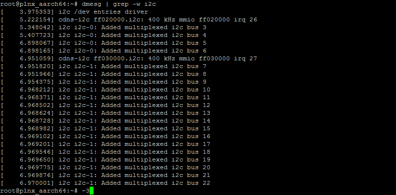
The testing observations (Kernel Logs) for I2C bus is mentioned hereafter. It can be seen from the kernel logs that under ideal scenario I2C is probed,
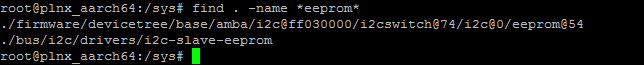
pins are properly configured, I2C bus entries are added and EEPROM is successfully attached over I2C, but under error scenarios pin control shouts for error,
no I2C busses are added as well as EEPROM node is not found.
Expected Output
Ideal ScenarioSuccessfully Probed pin control drivers

I2C pins configured via pin controller driver

I2C multiplexed busses added
Error Scenario
In this case invalid I2C pin groups were provided and it can be seen that pin control driver shouts error

Also no multiplexed I2C busses were added

EEPROM also was not added over I2C interface
Mainline Status
This Driver is not available at Mainline.
Patches sent to mainline, review in progress.
Change Log
2017.1Summary:
- pinctrl: zynqmp: Add pin controller driver
- pinctrl: zynqmp: Resolved pin conflicts
- pinctrl: zynqmp: 1bit and 4bit data lane support for sdio
- pinctrl: zynqmp: Updated pmu pin groups
- pinctrl: zynqmp: Warning on IO Standard mismatch
- pinctrl: zynqmp: Updated error handling in config set
- pinctrl: zynqmp: Added support for drive strength configuration
- pinctrl: zynqmp: Reset pin config when it's freed
- pinctrl: zynqmp: Fix code and documentation warnings
- a95257b pinctrl: zynqmp: Add pin controller driver
- 5b41a9c pinctrl: zynqmp: Resolved pin conflicts
- 19be687 pinctrl: zynqmp: 1bit and 4bit data lane support for sdio
- 2bbdb44 pinctrl: zynqmp: Updated pmu pin groups
- 17aabf1 pinctrl: zynqmp: Warning on IO Standard mismatch
- fa365ff pinctrl: zynqmp: Updated error handling in config set
- bdc3cb5 pinctrl: zynqmp: Added support for drive strength configuration
- 089db66 pinctrl: zynqmp: Reset pin config when it's freed
- 322b2e7 pinctrl: zynqmp: Fix code and documentation warnings
2017.2
- None
2017.3
Summary:
- pinctrl: zynqmp: make it explicitly non-modular
- pinctrl: zynqmp: Remove additional space in DRIVE_STRENGTH
- zynqmp: Use new firmware.h instead of pm.h
- 99158ea pinctrl: zynqmp: make it explicitly non-modular
- 67fd56e pinctrl: zynqmp: Remove additional space in DRIVE_STRENGTH
- 5e81ba5 zynqmp: Use new firmware.h instead of pm.h
2017.4
- None.
2018.1
Summary:
- Add new pincontrol driver which fetches pin information from firmware than using hardcoded pins in driver
Commits:
- 5807afd pinctrl: zynqmp: Correct mismatch between driver and binding doc
- e0a388f drivers: pinctrl: Update ZynqMP pin control driver
- None.
2019.1
- None.
2019.2
Summary:
- drivers: Defer probe if firmware is not ready
Commits:
- 6a63448: drivers: Defer probe if firmware is not ready
2020.1
Summary:
- pinctrl: zynqmp: use module_platform_driver to simplify the code
Commits:
- 065cafc: pinctrl: zynqmp: use module_platform_driver to simplify the code
2020.2
Summary:
- Minor: Fix coverity warnings
Commits:
Related Links
https://github.com/Xilinx/linux-xlnx/blob/master/drivers/pinctrl/pinctrl-zynqmp.c
CONFIG_PINCTRL=y
http://www.wiki.xilinx.com/ZynqMP%20Linux%20Pin%20Controller%20Driver