...
This design supports the following video interfaces:
Sources |
|
|---|---|
Sinks |
|
VCU Codec |
|
DPU | |
Streaming Interfaces | 1G Ethernet PS GEM |
Video Format | NV12 |
Supported Resolution | 4Kp30 |
1.3 VCU ROI Software
1.3.1 GStreamer Pipeline
...
The reference design has been tested successfully with the following user-supplied components.
HDMI Monitor:
Make/Model | Resolutions |
|---|---|
LG 27UD88 | 3840 x 2160 @ 30Hz |
Samsung LU28ES90DS/XL | 3840 x 2160 @ 30Hz |
Cable:
HDMI 2.0 compatible cable
The below table provides the performance information:
Resolution | FPS Achieved |
|---|---|
4Kp30 | 26 - 30 |
1080p30 | 30 |
Above FPS are measured withgop-mode=basic gop-length=60 b-frames=0 target-bitrate=1500 num-slices=8 control-rate=constant prefetch-buffer=true low-bandwidth=false qp-mode=roi encoder parameters for AVC and HEVC.
...
Connect the Micro USB cable into the ZCU106 Board Micro USB port J83, and the other end into an open USB port on the host PC. This cable is used for UART over USB communication.
Insert the SD card with the images copied into the SD card slot J100. Please find here how to prepare the SD card for a specific design.
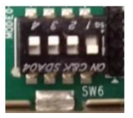
Set the SW6 switches as shown in the below Figure. This configures the boot settings to boot from SD.
Connect 12V Power to the ZCU106 6-Pin Molex connector
Connect one end of HDMI cable to the board’s P7 stacked HDMI connector (lower port) and another end to HDMI source
Connect one end of HDMI cable to the board’s P7 stacked HDMI connector (upper port) and another end to the HDMI monitor
For a USB storage device, connect the USB hub along with the mouse. (Optional)
For SATA storage device, connect SATA data cable to SATA 3.0 port. (Optional)
Set up a terminal session between a PC COM port and the serial port on the evaluation board (See the Determine which COM to use to access the USB serial port on the ZCU106 board for more details).
Copy the VCU-HDMI-ROI images into the SD card and insert the SD card on the board
The below images will show how to connect interfaces on the ZCU106 board
...
To Create SD Card with two partitions: Boot(FAT32+Bootable) and Root(EXT4) Refer this Link.
Copy
bootcontent fromrdf0428-zcu106-vcu-hdmi-roi-2020-1/image/bootto Boot partition in SD CardExtract
rootfs.ext4fromrdf0428-zcu106-vcu-hdmi-roi-2020-1/image/rootto Root partition in SD Card usingBoot the board with Flashed SD Card
...
To Create SD Card with two partitions: Boot(FAT32+Bootable) and Root(EXT4) Refer this Link.
For Build Flow refer this steps and copy mentioned generated dpu build images
bd.hwh BOOT.BIN boot.scr dpu.xclbin Image system.dtbinto BOOT partition of the SD card and extract generatedrootfs.ext4into ROOT partition of SD CardCopy the mentioned
bootcontentconfig, vitis, autostart.sh, setup.shfromrdf0428-zcu106-vcu-hdmi-roi-2020-1/image/boot/directory to Boot partition in SD CardBoot the board with Flashed SD Card
...
Build the hardware design
Code Block $ cd $DPU_TRD_HOME/prj/Vitis $ export EDGE_COMMON_SW=<Path to Petalinux Project>/xilinx-vcu-roi-zcu106-v2020.1-final/images/linux/image $ export SDX_PLATFORM=<Path to Vitis Workspace>/zcu106_dpu/export/zcu106_dpu/zcu106_dpu.xpfm $ make KERNEL=DPU DEVICE=zcu106
Generated SD card files are in
$DPU_TRD_HOME/prj/Vitis/binary_container_1/sd_card(SD card Format)Copy generated dpu build images from
$DPU_TRD_HOMEdirectory to$TRD_HOMEdirectoryCode Block $ cd $DPU_TRD_HOME/prj/Vitis/binary_container_1/sd_card $ cp bd.hwh BOOT.BIN boot.scr dpu.xclbin Image system.dtb $TRD_HOME/image/boot $ cp rootfs.ext4 $TRD_HOME/image/root
...