...
This tutorial shows how to build the Linux image and boot image using the PetaLinux build tool. This step assumes you have run through the PetaLinux project creation step in DM1 previously.
Run Flow Tutorial
To create a raw video file for playback, use the serial console and the
Parameters:
In the above example, 240 buffers equals to 4 seconds of video playback at 1080p60. The amount of memory required is about 1GB as the frames are raw. In this example the file is stored directly on the ramdisk i.e. in DDR memory. For best performance it is advised to store the file in DDR, or a USB3 or SATA drive. The SD card read performance will be slow.
Select the device-tree matching design module 10 and build all Linux image components. If you have run
petalinux-buildin a previous module, the build step will be incremental.Code Block language bash theme Midnight % cd $TRD_HOME/petalinux/bsp/project-spec/meta-user/recipes-bsp/device-tree/files/ % cp zcu102-base-dm10.dtsi system-user.dtsi % petalinux-build
Copy the DM9 bitstream and the
heartbeatapplication into the BSP. Create a boot image.Code Block language bash theme Midnight % cp $TRD_HOME/workspaces/ws_sdx/gstsdxfilter2d_system/Debug/_sds/p0/vivado/output/system.bit $TRD_HOME/workspaces/ws_heartbeat/heartbeat/Debug/heartbeat.elf $TRD_HOME/petalinux/bsp/images/linux % cd $TRD_HOME/petalinux/bsp/images/linux % petalinux-package --boot --bif=../../project-spec/boot/dm10.bif --force
Make a copy of the DM9 SD card image. Copy the
perfapm-serverapplication into the SD card directory. Replace the boot image and Linux image in the dm10 SD card directory.Code Block language bash theme Midnight % cp -rfr $TRD_HOME/sd_card/dm9 $TRD_HOME/sd_card/dm10-new % cp $TRD_HOME/workspaces/ws_perfapm-server/perfapm-server/Debug/perfapm-server.elf $TRD_HOME/sd_card/dm10-new % cp BOOT.BIN image.ub $TRD_HOME/sd_card/dm10-new
| Anchor | ||||
|---|---|---|---|---|
|
- See here for board setup instructions.
- Copy all the files from the
$TRD_HOME/sd_card/dm10-newSD card directory to a FAT formatted SD card. You can also use the prebuilt SD card image located at$TRD_HOME/sd_card/dm10instead. - Power on the board to boot the image; make sure INIT_B, done and all power rail LEDs are lit green.
- After ~30 seconds, the display will turn on and the application will start automatically, targeting the max supported resolution of the monitor (one of 3840x2160 or 1920x1080 or 1280x720).The application will detect whether DP Tx or HDMI Tx is connected and output on the corresponding display device.
To re-start the TRD application with the max supported resolution, run
Code Block language bash theme Midnight % run_video.sh
To re-start the TRD application with a specific supported resolution use the -r switch e.g. for 1920x1080, run
Code Block language bash theme Midnight % run_video.sh -r 1920x1080
- The user can now control the application from the GUI's control bar (bottom) displayed on the monitor.
- The user can select from the following video source options:
- TPG (SW): virtual video device that emulates a USB webcam purely in software
- USB: USB Webcam using the universal video class (UVC) driver
- TPG (PL): Test Pattern Generator implemented in the PL
- HDMI: HDMI input implemented in the PL
- CSI: MIPI CSI image sensor pipeline in the PL
- File: Read input from a raw video file
- The user can select from the following accelerator options:
- Passthrough (no accelerator)
- 2D convolution filter with configurable coefficients
- Dense optical flow algorithm
- The supported accelerator modes depend on the selected filter:
- SW - accelerator is run on A53 (filter2d only)
- HW - accelerator is run on PL
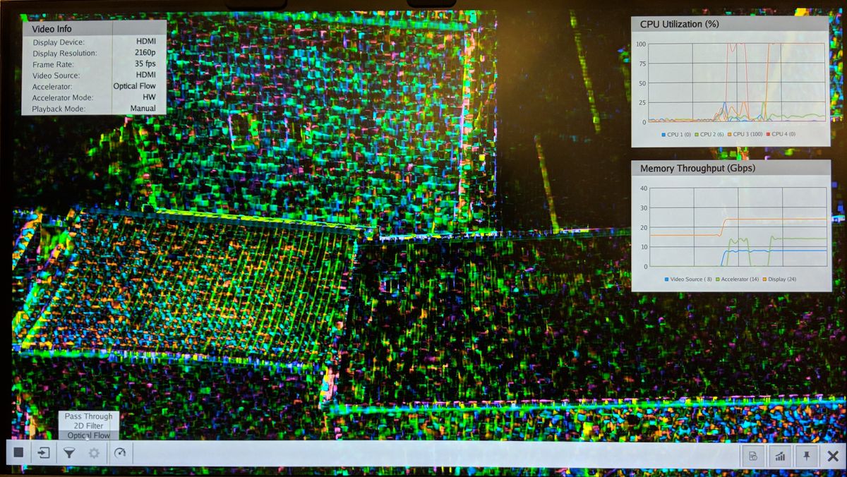
- The video info panel (top left) shows essential settings/statistics.
- The CPU utilization graph (top right) shows CPU load for each of the four A53 cores.
- The memory throughput graph (bottom right) shows memory traffic generated by video source, accelerator and display.
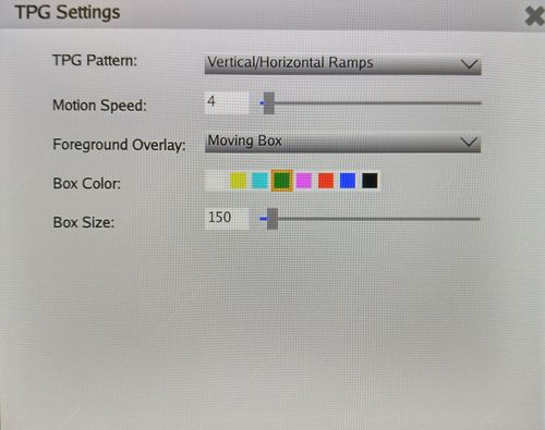
- The TPG settings panel gives access to advanced TPG controls:
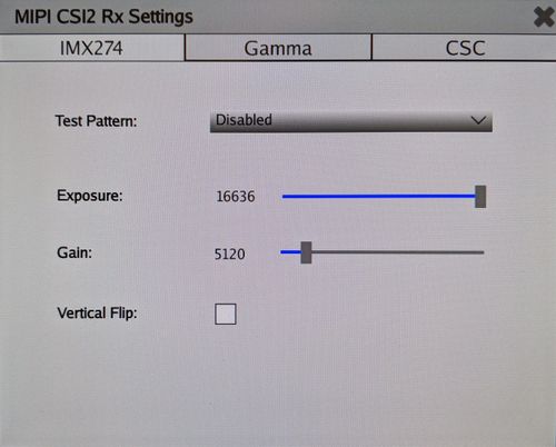
- The CSI settings panel gives access to advanced CSI controls including:
- Sony IMX274 image sensor
- Gamma control IP
- Color Correction IP (CSC)
- The 2D filter settings panel gives access to advanced filter controls:

- The demo mode settings panel allows the user to create a demo sequence combining video sources, accelerators, and modes:

- The file browser allows the user to select a video file for play back when file source is selected. The default video file path is set to
/home/root/demo.yuy2and if a video file is present there, the GUI will load it automatically.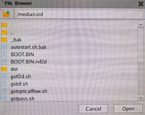
Raw Video File Creation (optional step)
To create a raw video file for playback, use the serial console and the
gst-launch-1.0 utility e.g.| Code Block | ||||
|---|---|---|---|---|
| ||||
% gst-launch-1.0 videotestsrc pattern=ball num-buffers=240 ! "video/x-raw, width=1920, height=1080, format=YUY2" ! filesink location=/home/root/demo.yuy2 |
num-buffersis the number of video frames to be capturedwidthandheightdefine the video resolution and should be matched with the display resolutionformatshould always be set to YUY2 as that is the expected format by the display and accelerator devices
In the above example, 240 buffers equals to 4 seconds of video playback at 1080p60. The amount of memory required is about 1GB as the frames are raw. In this example the file is stored directly on the ramdisk i.e. in DDR memory. For best performance it is advised to store the file in DDR, or a USB3 or SATA drive. The SD card read performance will be slow.
...