The purpose of this page is to describe the Linux SPI driver for Xilinx soft IPs.
| Table of Contents |
|---|
Overview
This information corresponds to the axi spi driver that's in the development branch of the GIT tree.This driver is also in the master branch, but not updated for device tree there.
It's in the development branch as a patch has been submitted to the mainline kernel so that it works
with the device tree and also finds nodes on the SPI such as an EEPROM.
HW/IP Features
- Configurable AXI4 interface; when configured with an AXI4-Lite interface the core is backward
compatible with version 1.00 of the core (legacy mode) - Configurable AXI4 interface for burst mode operation for the Data Receive Register (DRR)
and the Data Transmit Register (DTR) FIFO - Configurable eXecute In Place (XIP) mode of operation
- Connects as a 32-bit slave on either AXI4-Lite or AXI4 interface
- Configurable SPI modes:
- Standard SPI mode
- Dual SPI mode
- Quad SPI mode
- Programmable SPI clock phase and polarity
- Configurable FIFO depth (16 or 256 element deep in Dual/Quad/Standard SPI mode) and
fixed FIFO depth of 64 in XIP mode - Configurable Slave Memories in dual and quad modes are: Mixed, Micron, Winbond, and
Spansion (Beta Version)
Missing features, Known Issues and Limitations
- None
Kernel Configuration
SPI may not be enabled in the default kernel configuration. The following steps may be used to enable the driver in the kernel configuration.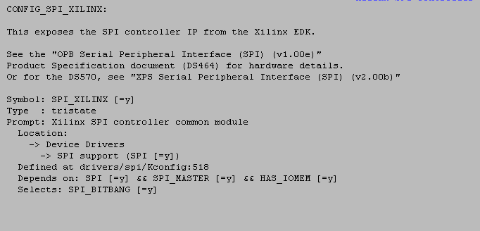
Using An SPI EEPROM Driver As A Higher Layer:
There are higher layer drivers that allow the SPI driver to be used to access other devices such as an SPI serial EEPROM. A change was needed in the SPI AT25 driver of the kernel to use device tree and this change is also in the development branch as it is being submitted to the mainline also.
The following steps may be used to enable the driver in the kernel configuration.
- From the device drivers menu, select SPI support
- Select SPI EEPROMs from most vendors
Devicetree Settings
Adding An SPI EEPROM to the Device Tree
The following example shows adding an SPI EEPROM to a device tree. This example was used to access an SPI EEPROM on the Aardvark board.The device-tree generator for the EDK does not create the EEPROM device on the SPI bus.
The value of 0 in the reg entry is the chip select for the EEPROM. The value in the spi-max-frequency is the bus frequency. This field is required, but has not been tested with other values.
| Code Block | ||
|---|---|---|
| ||
        xps_spi_0: xps-spi@84000000 {
            compatible = "xlnx,xps-spi-2.00.b";
            interrupt-parent = <&xps_intc_0>;
            interrupts = < 0 2 >;
            reg = < 0x84000000 0x1000 >;
            xlnx,family = "virtex4";
            xlnx,fifo-exist = <0x1>;
            xlnx,num-ss-bits = <0x1>;
            xlnx,num-transfer-bits = <0x8>;
            xlnx,sck-ratio = <0x20>;
            #address-cells = <1>;
            #size-cells = <0>;

            eeprom@0 {
                compatible = "at,at25";
                spi-max-frequency = <100000000>;
                reg = <0>;
                addr-size = <2>;
                page-size = <32>;
                eeprom-size = <1024>;
                eeprom-name = "johnsat25";
            };
        } ;
|
Adding a flash to the Device tree
| Code Block | ||
|---|---|---|
| ||
axi_quad_spi_1: spi@44a00000 {
                        compatible = "xlnx,axi-quad-spi-3.2", "xlnx,xps-spi-2.00.a";
                        interrupt-parent = <&axi_intc_1>;
                        interrupts = <1 0>;
                        reg = <0x44a00000 0x10000>;
                        xlnx,fifo-depth = <0x100>;
                        xlnx,instance = "axi_quad_spi_inst";
                        xlnx,num-ss-bits = <0x1>;
                        xlnx,num-transfer-bits = <0x8>;
                        xlnx,s-axi4-addr-width = <0x18>;
                        xlnx,s-axi4-data-width = <0x20>;
                        xlnx,s-axi4-id-width = <0x4>;
                        xlnx,sck-ratio = <0x2>;
                        xlnx,sck-ratio1 = <0x1>;
                        xlnx,spi-mem-addr-bits = <0x18>;
                        xlnx,spi-memory = <0x2>;
                        xlnx,spi-mode = <0x2>;
                        xlnx,sub-family = "kintex7";
                        xlnx,type-of-axi4-interface = <0x0>;
                        xlnx,use-startup = <0x1>;
                        xlnx,xip-mode = <0x0>;
                        #address-cells = <1>;
                        #size-cells = <0>;is-dual = <0>;
                        flash@0 {
                                  compatible = "n25q128";
                                  reg = <0x0>;
                                  spi-max-frequency = <50000000>;
                                  #address-cells = <1>;
                                  #size-cells = <1>;
                                  partition@test {
                                          label = "spi-flash";
                                          reg = <0x0 0x800000>;
                                  };
                      } ;
}; |
Test Procedure
SysFs Interface
The EEPROM driver allows the contents of the EEPROM to be seen in the sys file system at /sys/bus/spi/devices/spi32766.0/eeprom. The file, eeprom, is a file that can be read and written from user space.If the sys file system is not mounted (no /sys dir), then the following commands will create and mount it.
| Code Block | ||
|---|---|---|
| ||
> mkdir /sys
> mount -t sysfs sysfs sys |
| Code Block | ||
|---|---|---|
| ||
> more /sys/bus/spi/device/spi32766.0/eeprom | od -x |
| Code Block | ||
|---|---|---|
| ||
> echo 0123456789DEADBEEFCAFE > /sys/bus/spi/devices/spi32766.0/eeprom |
Using An Aardvark I2C/SPI Activity Board For SPI EEPROM Testing
TotalPhase, the company that sells the Aardvark I2C/SPI test equipment, also sells a small board that we can use for our own testing, independent of the Aardvark. The board has an I2C EEPROM and an SPI EEPROM on it such that it can be connected to an FPGA board pretty easy.http://www.totalphase.com/products/activity_board/
http://www.totalphase.com/download/pdf/activity-board-v1.00.pdf
http://www.totalphase.com/products/split_cable/
The point of this exercise is to have a standard test for the SPI that can be used across all boards.
See the following page, SPI With The Aardvark Board, for more information on how to do it.
Expected Log
| Code Block | ||
|---|---|---|
| ||
The following kernel output (or similar) shows the EEPROM driver was started.
xilinx-xps-spi 84000000.xps-spi: at 0x84000000 mapped to 0xC9014000, irq=20
at25 spi32766.0: 1 KByte johnsat25 eeprom, pagesize 32 |
Change Log
2016.3
- Summary
- None
- Commits
- None
2016.4
- Summary
- None
- Commits
- None
2017.1
2017.2
- Summary
- None
- Commits
- None
2017.3
2017.4
- Summary
- None
- Commits
- None
The purpose of this page is to describe the Linux SPI driver for Xilinx soft IPs.
| Table of Contents |
|---|
Overview
This information corresponds to the axi spi and axi quad-spi driver that's in the development branch of the GIT tree.This driver is also in the master branch, but not updated for device tree there.
It's in the development branch as a patch has been submitted to the mainline kernel so that it works
with the device tree and also finds nodes on the SPI such as an EEPROM.
HW/IP Features
- Configurable AXI4 interface; when configured with an AXI4-Lite interface the core is backward
compatible with version 1.00 of the core (legacy mode) - Configurable AXI4 interface for burst mode operation for the Data Receive Register (DRR)
and the Data Transmit Register (DTR) FIFO - Configurable eXecute In Place (XIP) mode of operation
- Connects as a 32-bit slave on either AXI4-Lite or AXI4 interface
- Configurable SPI modes:
- Standard SPI mode
- Dual SPI mode
- Quad SPI mode
- Programmable SPI clock phase and polarity
- Configurable FIFO depth (16 or 256 element deep in Dual/Quad/Standard SPI mode) and
fixed FIFO depth of 64 in XIP mode - Configurable Slave Memories in dual and quad modes are: Mixed, Micron, Winbond, and
Spansion (Beta Version)
Missing features, Known Issues and Limitations
- None
Kernel Configuration
SPI may not be enabled in the default kernel configuration. The following steps may be used to enable the driver in the kernel configuration.Using An SPI EEPROM Driver As A Higher Layer:
There are higher layer drivers that allow the SPI driver to be used to access other devices such as an SPI serial EEPROM.
The following steps may be used to enable the driver in the kernel configuration.
- From the device drivers menu, select SPI support
- Select SPI EEPROMs from most vendors
Devicetree Settings
Adding An SPI EEPROM to the Device Tree
The following example shows adding an SPI EEPROM to a device tree. This example was used to access an SPI EEPROM on the Aardvark board.The device-tree generator for the EDK does not create the EEPROM device on the SPI bus.
The value of 0 in the reg entry is the chip select for the EEPROM. The value in the spi-max-frequency is the bus frequency. This field is required, but has not been tested with other values.
| Code Block | ||
|---|---|---|
| ||
        xps_spi_0: xps-spi@84000000 {
            compatible = "xlnx,xps-spi-2.00.b";
            interrupt-parent = <&xps_intc_0>;
            interrupts = < 0 2 >;
            reg = < 0x84000000 0x1000 >;
            xlnx,family = "virtex4";
            xlnx,fifo-exist = <0x1>;
            xlnx,num-ss-bits = <0x1>;
            xlnx,num-transfer-bits = <0x8>;
            xlnx,sck-ratio = <0x20>;
            #address-cells = <1>;
            #size-cells = <0>;

            eeprom@0 {
                compatible = "at,at25";
                spi-max-frequency = <100000000>;
                reg = <0>;
                addr-size = <2>;
                page-size = <32>;
                eeprom-size = <1024>;
                eeprom-name = "johnsat25";
            };
        } ;
|
Adding a flash to the Device tree
| Code Block | ||
|---|---|---|
| ||
axi_quad_spi_1: spi@44a00000 {
                        compatible = "xlnx,axi-quad-spi-3.2", "xlnx,xps-spi-2.00.a";
                        interrupt-parent = <&axi_intc_1>;
                        interrupts = <1 0>;
                        reg = <0x44a00000 0x10000>;
                        xlnx,fifo-depth = <0x100>;
                        xlnx,instance = "axi_quad_spi_inst";
                        xlnx,num-ss-bits = <0x1>;
                        xlnx,num-transfer-bits = <0x8>;
                        xlnx,s-axi4-addr-width = <0x18>;
                        xlnx,s-axi4-data-width = <0x20>;
                        xlnx,s-axi4-id-width = <0x4>;
                        xlnx,sck-ratio = <0x2>;
                        xlnx,sck-ratio1 = <0x1>;
                        xlnx,spi-mem-addr-bits = <0x18>;
                        xlnx,spi-memory = <0x2>;
                        xlnx,spi-mode = <0x2>;
                        xlnx,sub-family = "kintex7";
                        xlnx,type-of-axi4-interface = <0x0>;
                        xlnx,use-startup = <0x1>;
                        xlnx,xip-mode = <0x0>;
                        #address-cells = <1>;
                        #size-cells = <0>;is-dual = <0>;
                        flash@0 {
                                  compatible = "n25q128";
                                  reg = <0x0>;
                                  spi-max-frequency = <50000000>;
                                  #address-cells = <1>;
                                  #size-cells = <1>;
                                  partition@test {
                                          label = "spi-flash";
                                          reg = <0x0 0x800000>;
                                  };
                      } ;
}; |
Test Procedure
SysFs Interface
The EEPROM driver allows the contents of the EEPROM to be seen in the sys file system at /sys/bus/spi/devices/spi32766.0/eeprom. The file, eeprom, is a file that can be read and written from user space.If the sys file system is not mounted (no /sys dir), then the following commands will create and mount it.
| Code Block | ||
|---|---|---|
| ||
> mkdir /sys
> mount -t sysfs sysfs sys |
| Code Block | ||
|---|---|---|
| ||
> more /sys/bus/spi/device/spi32766.0/eeprom | od -x |
| Code Block | ||
|---|---|---|
| ||
> echo 0123456789DEADBEEFCAFE > /sys/bus/spi/devices/spi32766.0/eeprom |
Using An Aardvark I2C/SPI Activity Board For SPI EEPROM Testing
TotalPhase, the company that sells the Aardvark I2C/SPI test equipment, also sells a small board that we can use for our own testing, independent of the Aardvark. The board has an I2C EEPROM and an SPI EEPROM on it such that it can be connected to an FPGA board pretty easy.http://www.totalphase.com/products/activity_board/
http://www.totalphase.com/download/pdf/activity-board-v1.00.pdf
http://www.totalphase.com/products/split_cable/
The point of this exercise is to have a standard test for the SPI that can be used across all boards.
See the following page, SPI With The Aardvark Board, for more information on how to do it.
Expected Log
| Code Block | ||
|---|---|---|
| ||
The following kernel output (or similar) shows the EEPROM driver was started.
xilinx-xps-spi 84000000.xps-spi: at 0x84000000 mapped to 0xC9014000, irq=20
at25 spi32766.0: 1 KByte johnsat25 eeprom, pagesize 32 |
Change Log
2016.3
- Summary
- None
- Commits
- None
- Summary
2016.4
- Summary
- None
- Commits
- None
- Summary
2017.1
2017.2
- Summary
- None
- Commits
- None
- Summary
2017.3
2017.4
- Summary
- None
- Commits
- None
- Summary
2018.1
- Summary
- None
- Commits
- None
- Summary
2018.2
- Summary
- Passed correct structure in pm calls
- Commits
- Summary
2018.3
- Summary
- None
- Commits
- None
- Summary
2019.1
2019.2
- Summary
- None
- Commits
- None
- Summary
2020.1
- Summary
- Updated axi-qspi controller driver in kernel v5.4 upgrade
- Commits
- Summary
2020.2
2021.1
- Summary
- None
- Commits
- None
- Summary
- 2018
2021.2
- Summary
- Passed correct structure in pm callsNone
- Commits
- 4c778ceNone
- Summary
2022.
31
- Summary
- None
- Commits
- None
- Summary
2022.
12
- Summary
- Added workaround when startup block is enabled
- Fixed kernel booting issue when startup block is Fix bits_per_word_mask
- Fix spi timeout issue with threaded irq enabled
- Commits
- Summary
2023.
21
- Summary
- NoneReplace all spi->chip_select and spi->cs_gpiod references with function call
- Commits
- Noneae655c5
- Summary
2023.
12
- Summary
- Updated axi-qspi controller driver in kernel v5.4 upgradeNone
- Commits
- ad7897eNone
- Summary
Related Links
...