This page provides all the information related to VCU Multi-Stream ROI TRD using Avnet Quad Sensor design for ZCU106.
Table of Contents
| Table of Contents | ||
|---|---|---|
|
1 Overview
The primary goal of this VCU Multi-Stream ROI TRD using Avnet Quad Sensor design is to demonstrate the use of Deep learning Processor Unit (DPU) block for extracting the Region of Interest (ROI) from input video frames and to use this information to perform ROI based encoding using Video Codec Unit (VCU) encoder hard block present in Zynq UltraScale+ EV devices. Video captures from the quad sensor connected through MIPI CSI-2 Rx which is implemented in the PL. The Avnet Multi-Camera FMC module is used to capture four video streams through a MIPI CSI-2 interface.
...
This ZCU106 VCU Multi Stream ROI TRD design supports only encoding feature of VCU. For decoding on ZCU106 Board-2 setup, needs to use VCU HDMI Single Stream ROI TRD design.
1.1 System Architecture
The following figure shows the block diagram of the ROI design
...
1.2 Hardware Architecture
This section gives a detailed description of the blocks used in the hardware design. The functional block diagram of the design is shown in the below figure.
...
Sources |
|
|---|---|
Sinks |
|
VCU Codec |
|
DPU | |
Streaming Interfaces | 1G Ethernet PS GEM |
Video Format | NV12 |
Supported Resolution | 4 x 1080P30 |
1.3 VCU ROI Software
1.3.1 Vitis Video Analytics SDK (VVAS)
VVAS is being developed to provide easy to use and scalable framework using which users will be able to build their solutions on Xilinx FPGA. VVAS provides infrastructure that will be covering a wide variety of applications in Embedded, Vision, Datacenter, Machine Learning, Automotive and many other domains.
...
VVAS Top-level Block diagram
1.3.2 Deep Learning Processor Unit (DPU)
DPU is a programmable engine optimized for deep neural networks. It is a group of parameterizable IP cores pre-implemented on the hardware with no place and route required. The DPU is released with the Vitis AI specialized instruction set, allowing efficient implementation of many deep learning networks.
...
DPU device is initialized
Instantiate a DPU Task from DPU Kernel and allocate corresponding DPU memory buffer
Set the input image to created DPU task
Run the DPU task to find the faces from the input image
DPU device is uninitialized
1.3.3 GStreamer Pipelines Flow
The GStreamer plugin demonstrates the DPU capabilities with Xilinx VCU encoder’s ROI (Region of Interest) feature. The plugin will detect ROI (i.e. face co-ordinates) from input frames using DPU IP and pass the detected ROI information to the Xilinx VCU encoder. The following figure shows the data flow for GStreamer pipeline of stream-out use case.
...
Stream-in the encoded data using RTP protocol
The Xilinx VCU decoder will decode the data
Display the decoded data on HDMI-Tx display
1.4 Software Tools and System Requirements
Hardware
Required:
Two ZCU106 evaluation board rev 1.0 with power cable
Monitor with HDMI input supporting 3840x2160 resolution or 1920x1080 resolution (e.g. LG 27UD88, Samsung LU28ES90DS/XL)
HDMI 2.0 certified cable
Class-10 SD card
Ethernet cable
...
Resolution | FPS Achieved |
|---|---|
4 x 1080p30 | 30 |
1.5 Board Setup
The below section will provide the information on the ZCU106 board setup for running ROI design.
Connect the Micro USB cable into the ZCU106 Board Micro USB port J83, and the other end into an open USB port on the host PC. This cable is used for UART over USB communication.
Insert the SD card with the images copied into the SD card slot J100. Please find here how to prepare the SD card for a specific design.
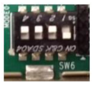
Set the SW6 switches as shown in the below Figure. This configures the boot settings to boot from SD.
Connect 12V Power to the ZCU106 6-Pin Molex connector
For a USB storage device, connect the USB hub along with the mouse. (Optional)
For SATA storage device, connect SATA data cable to SATA 3.0 port. (Optional)
For MIPI CSI-2, Insert the Avnet Multi-Camera FMC module into the FMC0 connector and set VADJ to 1.2V
Important Note: VADJ on the FMC0 connector must be set to 1.2V. See FMC VADJ Voltage Settings for more information.
Set up a terminal session between a PC COM port and the serial port on the evaluation board (See the Determine which COM to use to access the USB serial port on the ZCU106 board for more details).
Copy the VCU Multi Stream ROI TRD images into the SD card and insert the SD card on the board
The below images will show how to connect interfaces on the ZCU106 board
...
1.6 Run Flow
The VCU Multi Stream ROI TRD package is released with the source code, Vivado project, Petalinux BSP, and SD card image that enables the user to run the demonstration. It also includes the binaries necessary to configure and boot the ZCU106 board. Prior to running the steps mentioned in this wiki page, download the VCU Multi Stream ROI TRD package and extract its contents to a directory referred to as $TRD_HOME which is the home directory.
...
| Code Block |
|---|
├── image
  └──sd_card
    └──boot
        ├── autostart.sh
        ├── bd.hwh
        ├── BOOT.BIN
        ├── boot.scr
        ├── dpu.xclbin
        ├── Image
        ├── quad_sensor_isp_tuning.sh
        ├── quad_sensor_media_graph_setting.sh
        ├── setup.sh
        ├── system.dtb
        ├── vcu
        │   └── configure_qos.sh
        ├── vitis
        │   └── densebox_640_360-zcu102_zcu104_kv260-r1.4.0.tar.gz
        └── vvas
            └── json
└── kernel_ML.json |
1.6.1 Preparing the SD card
There are three ways to prepare the SD card for booting. Each method is detailed below.
...
All the required Densebox models are already available in
rdf0617-zcu106-vcu-multi-stream-roi-2021-1/image/sd_card/boot/vitisdirectory which are installed automatically during 1st time boot. Please wait till the target setup completes and models are installed.
1.6.2 GStreamer Pipelines using mediasrcbin plugin
This section covers the GSreamer pipelines using mediasrcbin plugin for serial and streaming ROI use-cases. This mediasrcbin plugin is Xilinx specific plugin which is a bin element on top of v4l2src. It parses and configures the media graph of a media device automatically.
...
Set IP address for the client:
Code Block ifconfig eth0 192.168.25.89
Run the following
gst-launch-1.0command for stream-in pipeline where5004is port numberStream-in Pipeline
Code Block gst-launch-1.0 udpsrc port=5004 buffer-size=60000000 caps="application/x-rtp, clock-rate=90000" ! rtpjitterbuffer latency=1000 ! rtpmp2tdepay ! tsparse ! video/mpegts ! tsdemux name=demux ! queue ! h265parse ! video/x-h265, profile=main, alignment=au ! omxh265dec internal-entropy-buffers=5 low-latency=0 split-input=true ! queue max-size-bytes=0 ! fpsdisplaysink name=fpssink text-overlay=false 'video-sink=kmssink bus-id=a00c0000.v_mix hold-extra-sample=1 show-preroll=false sync=true draw-roi=true roi-rectangle-thickness=3 roi-rectangle-color=<0,90,240>' sync=true -v
1.6.3 GStreamer Pipelines using v4l2src plugin
This section covers the GStreamer pipelines using v4l2src plugin for serial and streaming ROI use-cases.
...
Set IP address for the client:
Code Block ifconfig eth0 192.168.25.89
Run the following
gst-launch-1.0command for stream-in pipeline where5004is port numberStream-in Pipeline
Code Block gst-launch-1.0 udpsrc port=5004 buffer-size=60000000 caps="application/x-rtp, clock-rate=90000" ! rtpjitterbuffer latency=1000 ! rtpmp2tdepay ! tsparse ! video/mpegts ! tsdemux name=demux ! queue ! h265parse ! video/x-h265, profile=main, alignment=au ! omxh265dec internal-entropy-buffers=5 low-latency=0 split-input=true ! queue max-size-bytes=0 ! fpsdisplaysink name=fpssink text-overlay=false 'video-sink=kmssink bus-id=a00c0000.v_mix hold-extra-sample=1 show-preroll=false sync=true draw-roi=true roi-rectangle-thickness=3 roi-rectangle-color=<0,90,240>' sync=true -v
1.7 Build Flow
Refer below link to download the VCU Multi Stream ROI TRD package.
...
| Code Block |
|---|
export TRD_HOME=</path/to/downloaded/zipfile>/rdf0617-zcu106-vcu-multi-stream-roi-2021-1 |
1.7.1 Hardware Build Flow
This section explains the steps to build the hardware platform and generate XSA using the Vivado tool.
...
The DPU Data ports are connected to the HP0 Port(S_AXI_HP0_FPD) of PS .
The DPU Instruction port is connected to the S_AXI_HPC1 port of PS
The DPU S_AXI_Control port is connected to the M_AXI_HPM0_LPD port of PS through interconnect_hpm0_lpd
The DPU interrupt is connected to the axi interrupt controller dynamically
1.7.2 Petalinux build Flow
This tutorial shows how to build the Linux image and boot image using the PetaLinux build tool.
...
Build the PetaLinux project
Code Block petalinux-build
1.7.3 Prepare Build Artifacts for Platform Creation
To prepare artifacts required for ZCU106 Vitis platform creation, follow the below steps after petalinux build
Go to the petalinux build image directory
Code Block cd $TRD_HOME/apu/vcu_petalinux_bsp/xilinx-vcu-multi-stream-roi-zcu106-v2021.1-final/images/linux
Create
linux.biffile as below inimages/linuxdirectory.linux.biffile is required to create ZCU106 Vitis platform which has information related to boot components. After zcu106 vitis platform creation thislinux.biffile will be part of the platform, which is required to build DPU and generate finalBOOT.BINCode Block /* linux */ the_ROM_image: { [bootloader, destination_cpu = a53-0] <zynqmp_fsbl.elf> [pmufw_image] <pmufw.elf> [destination_device=pl] <bitstream> [destination_cpu=a53-0, exception_level=el-3, trustzone] <bl31.elf> [destination_cpu=a53-0, load=0x00100000] <system.dtb> [destination_cpu=a53-0, exception_level=el-2] <u-boot.elf> }Copy generated images into boot and image directory by following the below commands. Use created
linux.bifto copy into boot directory.Code Block mkdir boot image cp linux.bif bl31.elf pmufw.elf system.dtb u-boot.elf zynqmp_fsbl.elf boot/. cp boot.scr system.dtb image/.
1.7.4 ZCU106 Platform Creation
This section shows how to create a Vitis acceleration platform for the zcu106 using the Vitis IDE.
...
As shown in below image, zcu106_dpu.xpfm is created under zcu106_dpu > export > zcu106_dpu > zcu106_dpu.xpfm
...
1.7.5 DPU Build
It is recommended to follow the build steps in sequence
Make sure parted utility is installed for DPU build
...
For more detail please refer DPU Build Flow
For more details on Vitis AI, check User Guide (UG1414)
2 Other Information
2.1 Known Issues
For Petalinux related known issues please refer PetaLinux 2021.1 - Product Update Release Notes and Known Issues.
For VCU related known issues please refer AR# 66763: LogiCORE H.264/H.265 Video Codec Unit (VCU) - Release Notes and Known Issues and Xilinx Zynq UltraScale+ MPSoC Video Codec Unit.
Memory leakage has been observed while running the multi-stream ROI pipeline for longer period of time.
2.2 Limitations
For Petalinux related limitations please refer PetaLinux 2021.1 - Product Update Release Notes and Known Issues.
For VCU related limitations please refer AR# 66763: LogiCORE H.264/H.265 Video Codec Unit (VCU) - Release Notes and Known Issues, Xilinx Zynq UltraScale+ MPSoC Video Codec Unit and PG252 link.
3 Appendix A - MIPI CSI-2 Rx Link-up
This section covers configuration of CSI-2 Rx using
media-ctlutility, along with demonstrating CSI-2 Rx link-up issues.Run the below command for media node to print media device topology where
"media0"represents media node.Code Block media-ctl -p -d /dev/media0
When MIPI CSI-2 Rx source is connected, it shows as below:
...