Programming Clocks on the ZCU111
This wiki will discuss the on-board ZCU111 clock topology and how these can be programmed via Linux (i2c-tool) or via a C application on the A53.
Table of Contents
ZCU111 Board Clocks Topology:
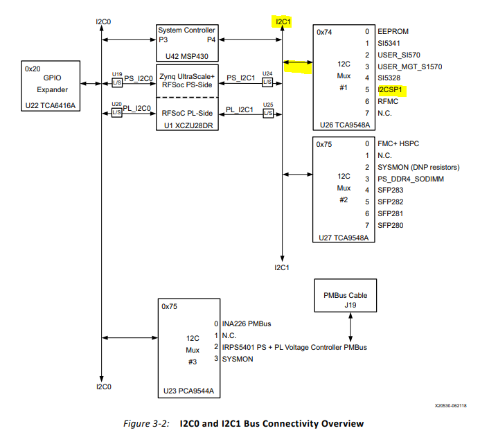
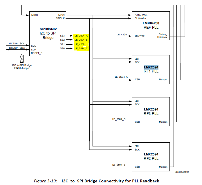
The clocking structure on the ZCU111 can be seen on page 54 here. The Clock sources; LMK04208 and LMX2594 are accessible via the I2CSPI over the IC21 bus:
The device-tree node for this can be seen here:
i2c@5 {
    #address-cells = <1>;
    #size-cells = <0>;
    reg = <5>;
    sc18is603@2f { /* sc18is602 - u93 */
        compatible = "nxp,sc18is603";
        reg = <0x2f>;
        /* 4 gpios for CS not handled by driver */
        /*
        * USB2ANY cable or
        * LMK04208 - u90 or
        * LMX2594 - u102 or
        * LMX2594 - u103 or
        * LMX2594 - u104
        */
    };
};
As shown in the sc18is603 device node, there are 4 CS for each clock source:
- LE_2494_A (LMX RF1 PLL) = 0x8
- LE_2594_B (LMX RF2 PLL) = 0x4
- LE_4208 (LMK) = 0x2
- LE_2594_C (LMX RF3 PLL) = 0x1
ZCU111 Board Clocks Programming:
There is source code provided in the RFDC driver example; xrfdc_clk.c and xrfdc_clk.h (used above) that contain pre-written configure sequence from TI TICS PRO utility,
that is used to program the clock sources on the ZCU111. Users can also use the i2c-tools utility in Linux to program these clocks. Both flows are discussed below
LMK04208:
This is the low noise jitter cleaner that feds the LMK2594. The LMX2594 is programmed using 24-bit shift registers. The shift register consists of a R/W bit (MSB), followed
by a 7-bit address field and a 16-bit data field. For the R/W bit, 0 is for write, and 1 is for read. The address field
ADDRESS[6:0] is used to decode the internal register address. The remaining 16 bits form the data field DATA[15:0].
LMX2594:
The LMX is programmed using 24 bit shift register. This is the clock provides the clock to the tiles on the RFDC:
LMK04208 C Code Programming:
The LMK04208 can be programmed via a C code application delivered with the RFDC driver, the code snippet is shown below.
#ifdef XPS_BOARD_ZCU111
unsigned int LMK04208_CKin[1][26] = {
  {0x00160040,0x80140320,0x80140321,0x80140322,
  0xC0140023,0x40140024,0x80141E05,0x03300006,0x01300007,0x06010008,
  0x55555549,0x9102410A,0x0401100B,0x1B0C006C,0x2302886D,0x0200000E,
  0x8000800F,0xC1550410,0x00000058,0x02C9C419,0x8FA8001A,0x10001E1B,
  0x0021201C,0x0180033D,0x0200033E,0x003F001F }};
#endif
LMX2594 C Code programming:
The LMK04208 can be programmed via a C code application delivered with the RFDC driver, the code snippet is shown below.
There are pre-configured sequences in the code that will allow the user to use one any of the frequencies below:
5120000 3932160 1474560 4915200 6553600 6400000 6389760 6144000 5898240 5734400 4000000 4096000 4423680
4669440 1966080 2048000 2457600 2949120 3072000 3276800 245760 3686400 204800 409600 491520 737280 7340032
These two functions can be called in the user application as shown below:
LMK04208ClockConfig(12, LMK04208_CKin);
LMX2594ClockConfig(12, 3932160);
ZCU111
ZCU111 BOARD
If using the rfdc example code, then the user will need to set the #define XPS_BOARD_ZCU111.
This can be passed as a symbol in C/C++ Build Settings in SDK (see above)
Or, via the (zcu111-zynqmp) YOCTO MACHINE NAME in Petalinux/Yocto
Using i2c-tools to program the LMK and LMX devices:
Users can use the i2cdetect utility to read all the devices on the I2C bus. For example:
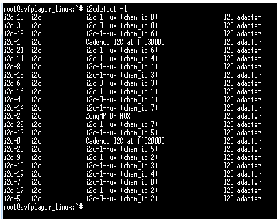
Here, the driver will “hop” through each mux to show all possible devices in the i2c bus topology.
In order to program the LMK or LMX devices on the ZCU111, users will need to find the SCI18IS60C device on the I2C bus.
To do this, users can do a i2cdetect -y -r busaddr
Where the busaddr would be 0 to 22 in this case (as per the i2cdetect -l command above).
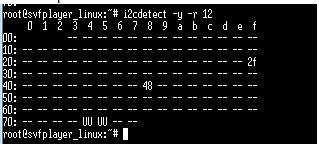
Users can do a grep on the result to see if the 0x2f (as we seen form the device node above is the SCI18IS60C device).
If the i2c bus topology isnt likely to change, then we can just hard-code this address into the script command.
However, if the bus topology is likely to change, ie add remove i2c from PS or AXI I2C in the PL, then user can script around this to dynamically find the SCI18IS60C device
For example, the function below will search through all possible bus addresses, and do a grep until it finds the expected device ID (0x2f):
fFindSCI18IS602 () {
   printf "Scanning for SCI18IS602... "
   for (( ii=0; ii<30; ii++ )); do
      #ls -l /dev/i2c* | grep i2c-${ii} > /dev/null
      #if [ $? -eq 0 ]; then
      if [ -e /dev/i2c-${ii} ]; then
         # Check for SCI18IS602
         #echo "i2c-${ii} bus:"
         i2cdetect -y -r ${ii} | grep -i $vSCI18IS602Addr > /dev/null
         if [ $? -eq 0 ]; then
            vSCI18IS602Bus=${ii}
            vSCI18IS602Addr="0x${vSCI18IS602Addr}"
            echo "Detected SCI18IS602 at bus=${vSCI18IS602Bus}, address=${vSCI18IS602Addr}."
            vSCI18IS602Found=1
         fi
      fi
   done
   if [ $vSCI18IS602Found -eq 0 ]; then
      echo "Warning: SCI18IS602 device not found!"
   fi
}
Now, that the bus address for the SCI18IS602 device is found. we can access the various clocks by passing the CS. The various CS can be seen below:
- LE_2494_A (LMX RF1 PLL) = 0x8
- LE_2594_B (LMX RF2 PLL) = 0x4
- LE_4208 (LMK) = 0x2
- LE_2594_C (LMX RF3 PLL) = 0x1
To target the LMK, then the i2cset command would look like:
i2cset -y 12 0x2f 0x2 <32 bit data> i
To target the LMX, then the i2cset command would look like:
i2cset -y 12 0x2f 0x1 <24 bit data> i
i2cset -y 12 0x2f 0x4 <24 bit data> i
i2cset -y 12 0x2f 0x8 <24 bit data> i
The data can be created using the TICS Pro tool from TI. This script can be passed to the Petalinux project as shown below:
petalinux-create --type apps --template install --name bootscript –enable
update the project-spec\meta-user\recipes-apps\bootscript\bootscript.bb:
#
# This file is the bootscript recipe.
#

SUMMARY = "Simple bootscript application"
SECTION = "PETALINUX/apps"
LICENSE = "MIT"
LIC_FILES_CHKSUM = "file://${COMMON_LICENSE_DIR}/MIT;md5=0835ade698e0bcf8506ecda2f7b4f302"

SRC_URI = "file://bootscript \
    "

S = "${WORKDIR}"

inherit update-rc.d

INITSCRIPT_NAME = "bootscript"
INITSCRIPT_PARAMS = "start 99 S ."

do_install() {
        install -d ${D}${sysconfdir}/init.d
        install -m 0755 ${S}/bootscript ${D}${sysconfdir}/init.d/bootscript
}
FILES_${PN} += "${sysconfdir}/*"
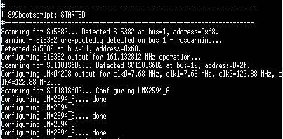
Then update the project-spec\meta-user\recipes-apps\bootscript\files\bootscript with the i2cset commands (also attached below):
warning
The script here is only provided for reference purpose only, and has not been fully tested!
This script should be auto-ran upon boot:
© Copyright 2019 - 2022 Xilinx Inc. Privacy Policy