Zynq UltraScale MPSoC Base TRD 2016.4 - Design Module 7
Zynq UltraScale MPSoC Base TRD 2016.4 - Design Module 7
Return to the Design Tutorials Overview.
Design Overview
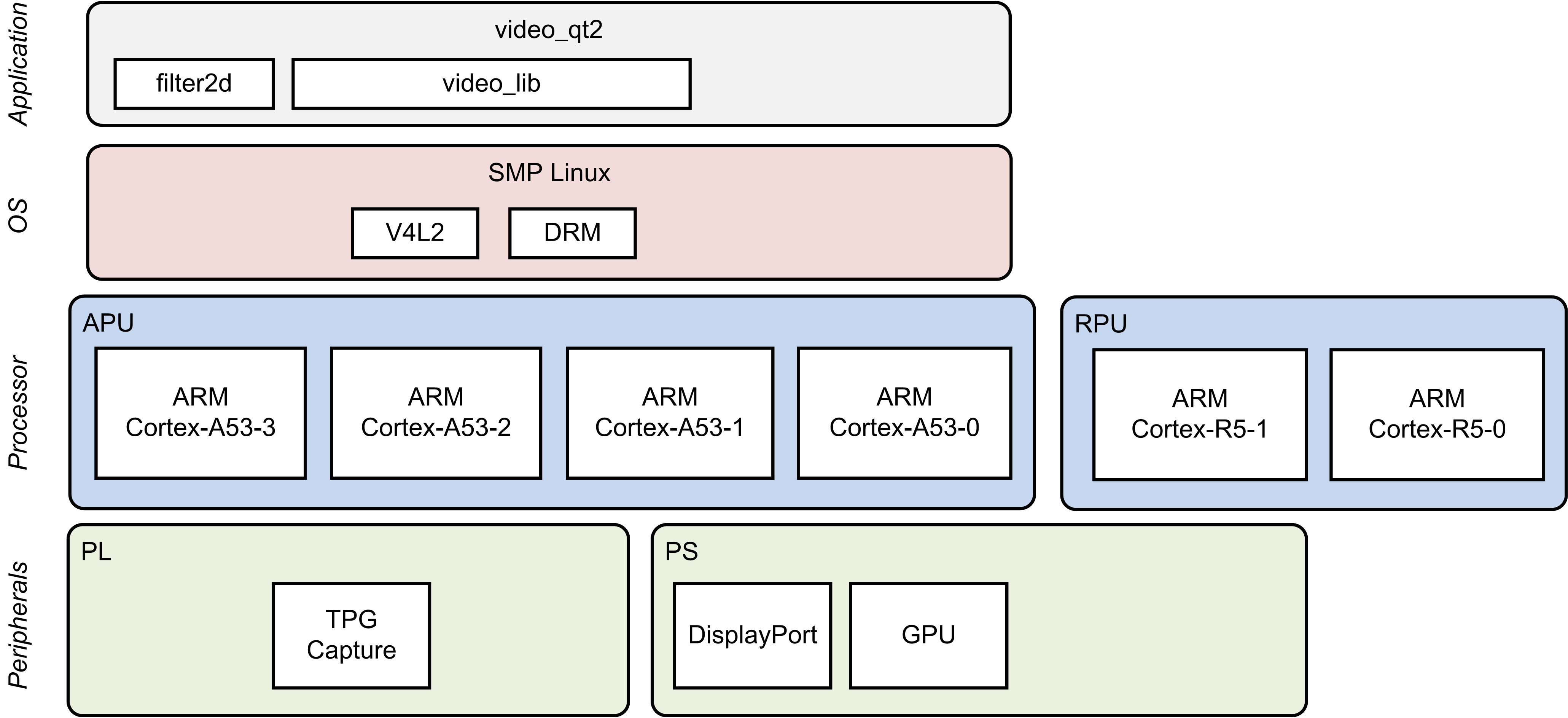
This module shows how to add a 2D convolution filter between the capture pipeline and the display. The 2D filter is implemented purely in software using the OpenCV library.
Design Components
This module requires the following components:
- zcu102_base_trd (SDSoC)
- pmu_fw
- petalinux_bsp
- zynqmp_fsbl
- bl31
- u-boot
- kernel
- device tree
- rootfs
- filter2d (SW)
- video_lib
- video_qt2
Build Flow Tutorials
2D Filter Sample
This tutorial shows how to build the OpenCV version of the 2D filter sample based on the Base TRD SDSoC platform.
Follow the steps in design module 5 to create a new workspace and to import the video_lib and video_qt2 projects. Otherwise, open the existing XSDK workspace only this time using the SDx tool instead of XSDK.
% cd $TRD_HOME/apu/video_app
% sdx -workspace . &&
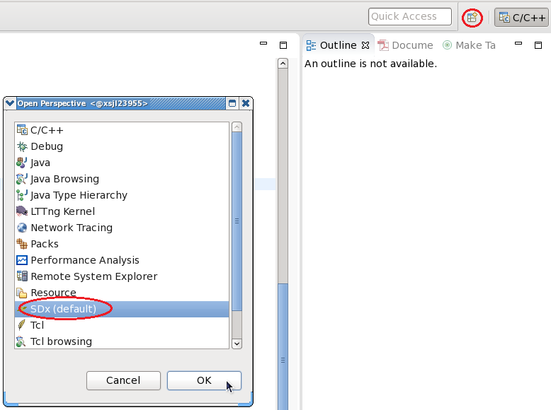
- Change the eclipse perspective to 'SDx' instead of 'C/C++' which is the current selection.
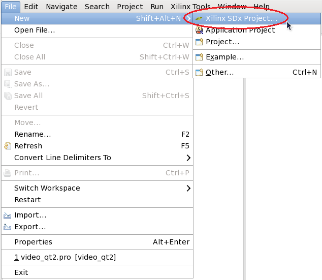
- Create a new SDx Project
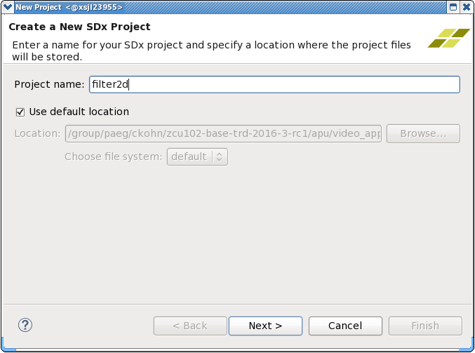
- Enter 'filter2d' as project name
- Click 'Add Custom Platform', browse to the $TRD_HOME/apu/zcu102_base_trd directory and confirm. Select the newly added 'zcu102_base_trd (custom)' platform from the list and click 'Next'.
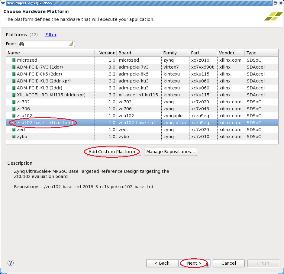
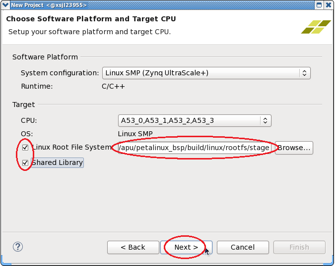
- Check the 'Linux Root File System' box and browse to the $TRD_HOME/apu/petalinux_bsp/build/linux/rootfs/stage directory. This assumes the petalinux-build command has been run in a previous module.
- Check the 'Shared Library' box and click 'Next'.
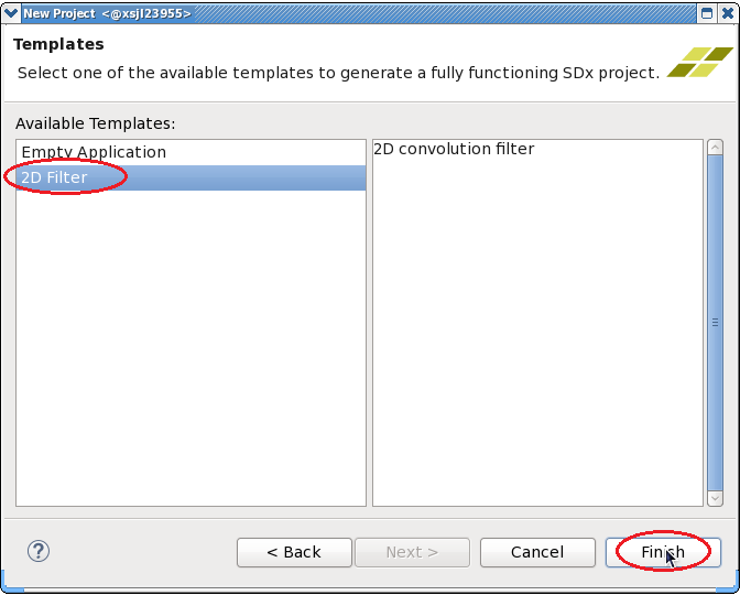
- Select the '2D Filter' template and click 'Finish'.
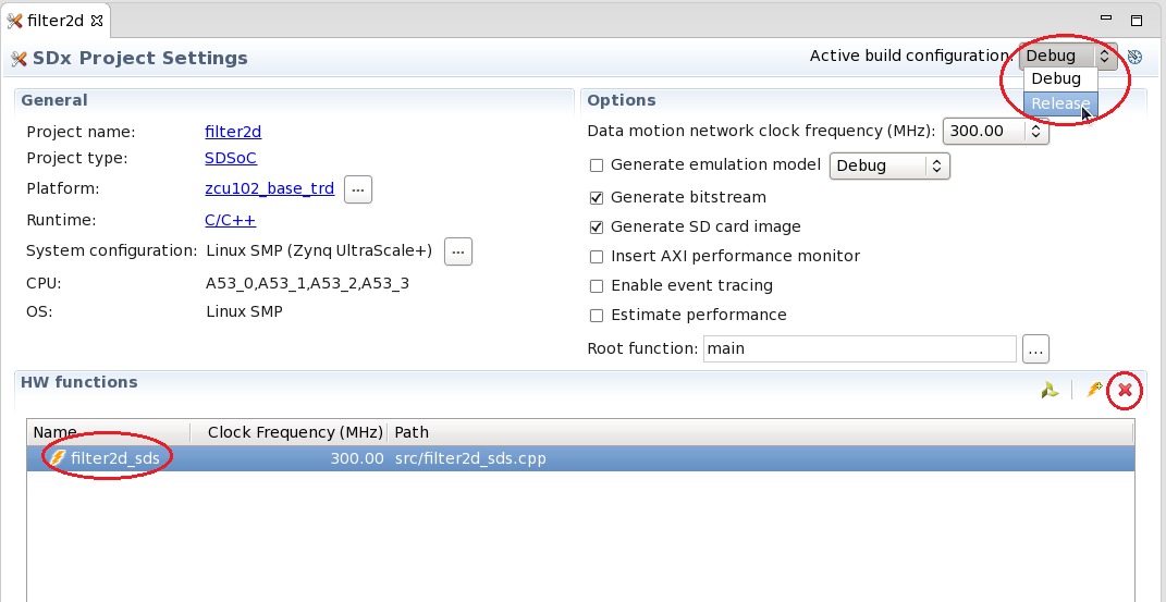
- Change the 'Active build configuration' to Release in the SDx Project Settings window.
- Remove the filter2d_sds HW function by highlighting the function name and clicking the red X symbol.
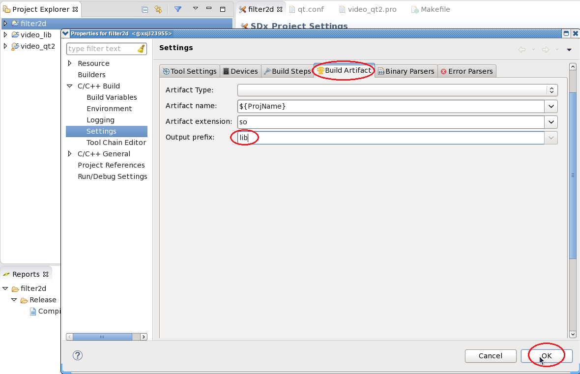
- Right-click the filter2d project, select 'C/C++ Build Settings'. Navigate to the 'Build Artifacts' tab and add the output prefix 'lib'. Click OK.
- Right-click the filter2d project and select 'Build Project'.

Copy the content of the generated sd_card folder to the dm7 SD card directory
% mkdir -p $TRD_HOME/images/dm7/bin
% cp -rf filter2d/Release/sd_card/* $TRD_HOME/images/dm7/
Video Qt Application
This tutorial shows how to build the video library and the video Qt application.
- Right-click the video_lib project, select 'C/C++ Build Settings'. Add the symbol 'WITH_SDSOC' and click OK.

Source the Qt setup script to re-generate the Qt Makefile reflecting these changes.
% cd $TRD_HOME/apu/video_app/video_qt2
% source qmake_set_env.sh
% qmake video_qt2-dm7.pro -r -spec linux-oe-g++
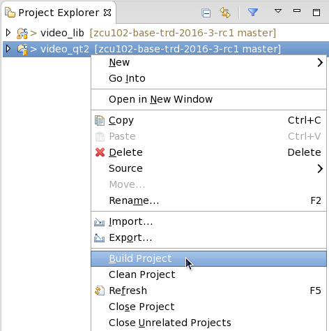
- Right-click the video_qt project and click 'Build Project'.
Copy the generated video_qt2 executable to the dm7 SD card directory.
% cp -f video_qt2 run_video.sh video_qt2_wrap.sh $TRD_HOME/images/dm7/bin/
Run Flow Tutorial
- See here for board setup instructions.
- Copy all the files from the $TRD_HOME/images/dm7 SD card directory to a FAT formatted SD card.
- Power on the board to boot the images; make sure INIT_B, done and all power rail LEDs are lit green.
- After ~30 seconds, the display will turn on and the application will start automatically, targeting the max supported resolution of the monitor (one of 3840x2160 or 1920x1080 or 1280x720).
Upon application exit, use the below login and password to log into the framebuffer or serial console:
root@Xilinx-ZCU102-2016_3 login: root
password: root
- The SD card file system is mounted at /media/card
- To re-start the TRD application type run_video.sh
- The user can now control the application from the GUI's control bar (bottom) displayed on the monitor.
- By default, application launches with VIVID as a video-source, user can also select TPG from the "Video-source selection" button present on the GUI's control-bar.
- Virtual Video Device (VIVID): emulates a USB webcam purely in software
- USB Webcam (UVC): using the universal video class driver
- Test Pattern Generator (TPG); implemented in the PL
- A 2D convolution filter can be turned on and different filter presets can be selected; the following filter modes are available:
- OFF - accelerator is disabled/bypassed
- SW - accelerator is run on A53 using OpenCV algorithm
- HW - accelerator is run on A53 using HLS algorithm
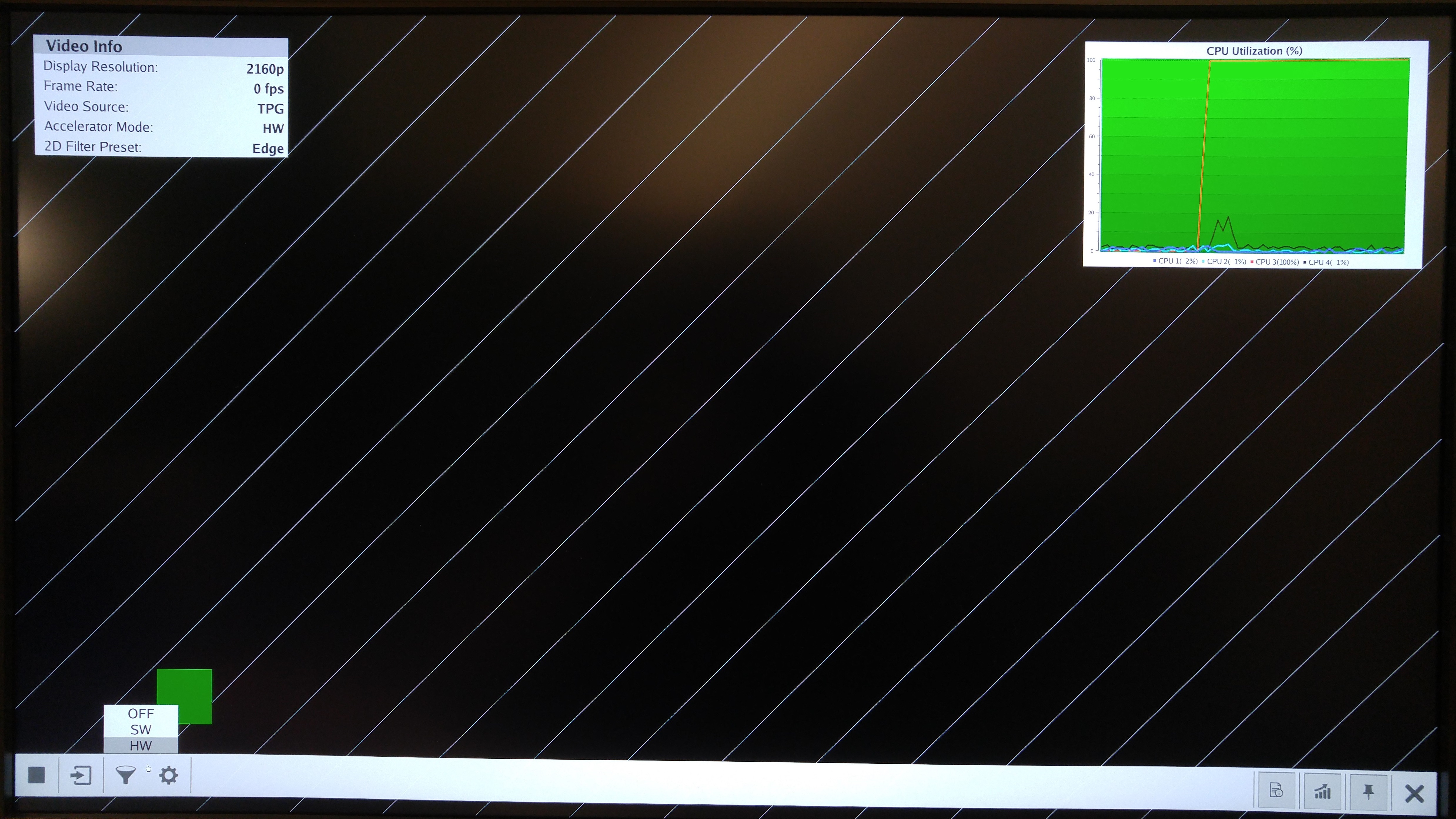
- The video info panel (top left) shows essential settings/statistics.
- The CPU utilization graph (top right) shows CPU load for each of the four A53 cores.
© Copyright 2019 - 2022 Xilinx Inc. Privacy Policy