DTG Common clock framework
Common Clock framework support in DTG
Description : Common clock framework support in the DTG. The pl clocks will be generated based on the below four cases.
Case1) Design which has PL IPs connected to any of the pl_clk
As from the above diagram the PL IPs axi_gpio_0,axi_gpio_1 and axi_uartlite_0 gets the clock source from pl_clk0.
The DTG will generate the device tree entries for the three PL IPs would be like below
axi_gpio_0: {
clock-names = "s_axi_aclk";
clocks = <&clkc 71>;
};
axi_gpio_1: {
clock-names = "s_axi_aclk";
clocks = <&clkc 71>;
};
axi_uartlite_0: {
clock-names = "s_axi_aclk";
clocks = <&clkc 71>;
};
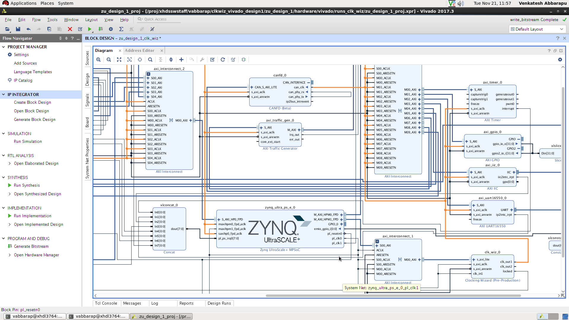
Case2) Design with the clock wizard where s_axi_aclk and clk_in1 gets the clock source from any of the pl_clks.
As from the diagram the PL IPs axi_gpio, axi_iic, canfd, axi_traffic_gen, axi_uart16550_0 and axi_timer gets the clock source from clock wizard clk_out1.
The clk_wiz_0 input clock pins clk_in1 and s_axi_aclk gets source from pl_clk0.
The DTG will generate the device tree entries for the PL IPs would be like below
axi_gpio_0: gpio@a0001000 {
clock-names = "s_axi_aclk";
clocks = <&clk_wiz_0 1>;
};
axi_iic_0: i2c@a0000000 {
clock-names = "s_axi_aclk";
clocks = <&clk_wiz_0 1>;
};
axi_timer_0: timer@a0003000 {
clock-names = "s_axi_aclk";
clocks = <&clk_wiz_0 1>;
};
axi_traffic_gen_0: axi_traffic_gen@a0020000 {
clock-names = "s_axi_aclk";
clocks = <&clk_wiz_0 1>;
};
axi_uart16550_0: serial@a0004000 {
clock-names = "s_axi_aclk";
clocks = <&clk_wiz_0 1>;
};
canfd_0: canfd@a0006000 {
clock-names = "can_clk", "s_axi_aclk";
clocks = <&clk_wiz_0 1>, <&clk_wiz_0 1>;
};
clk_wiz_0: clk_wiz@b0000000 {
#clock-cells = <1>;
clock-names = "clk_in1", "s_axi_aclk";
clock-output-names = "clk_out0", "clk_out1", "clk_out2", "clk_out3", "clk_out4", "clk_out5", "clk_out6", "clk_out7";
clocks = <&clkc 71>, <&clkc 71>;
compatible = "xlnx,clocking-wizard";
reg = <0x0 0xb0000000 0x0 0x10000>;
};
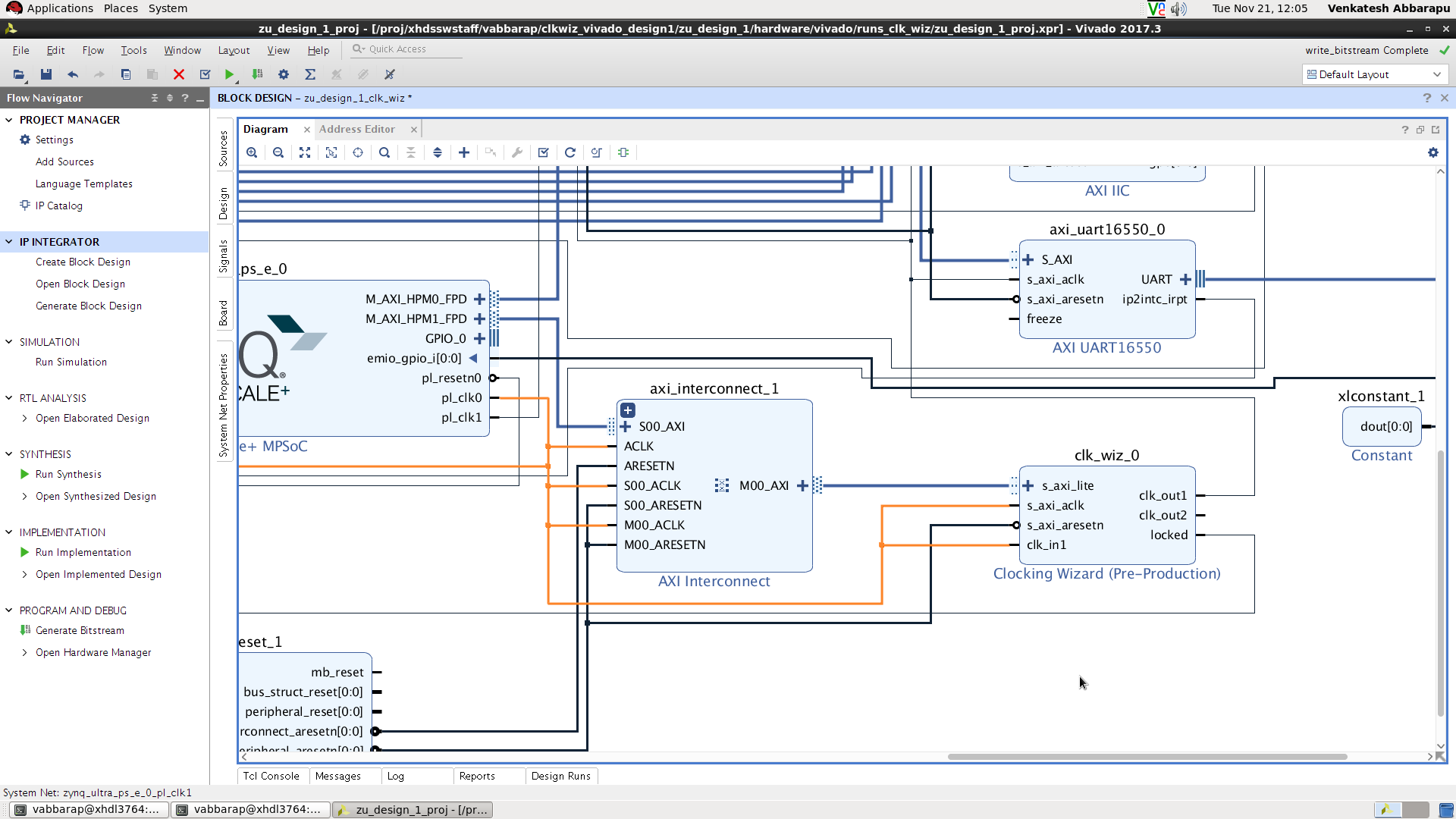
Case3) Design with the clock wizard which doesnt have the s_axi_aclk and clk_in1.
As from the diagram the PL IPs axi_gpio, axi_iic, canfd, axi_traffic_gen, axi_uart16550_0 and axi_timer gets the clock source from clock wizard clk_out1.
We generate the fixed-clock.
The DTG will generate the device tree entries for the PL IPs would be like below
axi_gpio_0: gpio@a0001000 {
clock-names = "s_axi_aclk";
clocks = <&misc_clk_0>;
};
axi_timer_0: timer@a0003000 {
clock-names = "s_axi_aclk";
clocks = <&misc_clk_0>;
};
axi_traffic_gen_0: axi_traffic_gen@a0020000 {
clock-names = "s_axi_aclk";
clocks = <&misc_clk_0>;
};
axi_uart16550_0: serial@a0004000 {
clock-names = "s_axi_aclk";
clocks = <&misc_clk_0>;
};
canfd_0: canfd@a0006000 {
clock-names = "can_clk", "s_axi_aclk";
clocks = <&misc_clk_0>, <&misc_clk_0>;
};
misc_clk_0: misc_clk_0 {
#clock-cells = <0>;
clock-frequency = <100000000>;
compatible = "fixed-clock";
};
Case 4) Design with the clock wizard where there is no s_axi_aclk but clk_in1 gets the clock source from pl_clk*
The axi_gpio_0 and axi_gpio_1 gets the clock source from clock wizards clk_out1
The clock wizard doesnt have the axi_clk and the clk_in1 gets the source from pl_clk1.
There wont be any node for clock wizard. As the clk_in1 gets the source from pl_clk1 enable the fclk1 node in pcw.dts.
we generate the fixed-clock.
The DTG will generate the device tree entries for the PL IPs would be like below
axi_gpio_0: gpio@b0000000 {
clock-names = "s_axi_aclk";
clocks = <&misc_clk_0>;
};
axi_gpio_1: gpio@b1000000 {
clock-names = "s_axi_aclk";
clocks = <&misc_clk_0>;
};
misc_clk_0: misc_clk_0 {
#clock-cells = <0>;
clock-frequency = <99999533>;
compatible = "fixed-clock";
};
From pcw.dtsi
&fclk1 {
status = "okay";
};
NOTE: when clock wizard doesnt have a s_axi_aclk the DTG will throw warning as below
WARNING: no s_axi_aclk for clockwizard
Related Links
© Copyright 2019 - 2022 Xilinx Inc. Privacy Policy
.png?version=1&modificationDate=1536675900785&cacheVersion=1&api=v2)


