reVISION Getting Started Guide 2017.4 rev2
Table of Contents
1 Revision History
This Getting Started Guide complements the 2017.4 rev2 version of the ZCU102 and ZCU104 reVISION platforms.
For other versions, refer to the reVISION Getting Started Guide overview page.
Change Log:
rev2
- ZCU102 and ZCU104 boards are supported
- Samples now use the GStreamer framework, included with the reVISION platform
- Sample design examples are built as GStreamer plugins
- Sample apps are included, to exercise the sample plugins
- Modified the samples directory structure, with a new workspace structure provided for the user
- Improved and augmented many features of the xfopencv library
rev1
- Update to 2017.4 SDSoC tools version
- Update to 2017.4 xfOpenCV libraries version
- Update to 2017.4 IP version
- Cascade platform interrupts to PS GIC using AXI interrupt controller
- Enable HP2 port in platform
- Use Sony IMX274 v4l2 subdevice driver
- Add filter2d live IO sample
- Minor fixes and improvements
2 Introduction
The Xilinx reVISION stack includes a range of development resources for platform, algorithm and application development. This includes support for the most popular neural networks including AlexNet, GoogLeNet, VGG, SSD, and FCN. Additionally, the stack provides library elements including pre-defined and optimized implementations for CNN network layers, required to build custom neural networks (DNN/CNN). The machine learning elements are complemented by a broad set of acceleration ready OpenCV functions for computer vision processing. For application level development, Xilinx supports industry standard frameworks and libraries including Caffe for machine learning and OpenCV for computer vision. The reVISION stack also includes development platforms from Xilinx and third parties, including various types of sensors. For more information go to the Xilinx reVISION webpage.
3 Overview
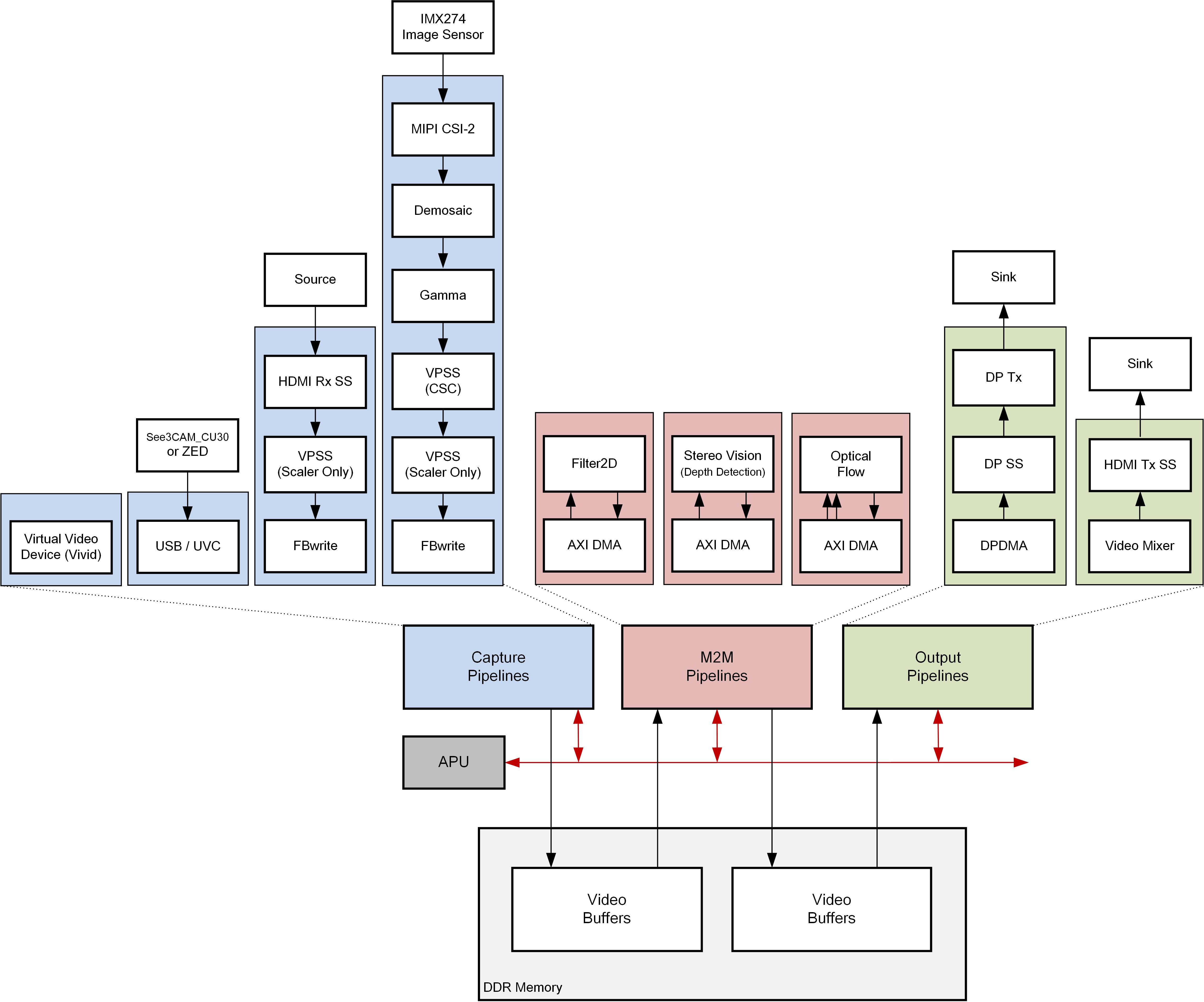
The below figure shows a block diagram of the reVISION single sensor design:
- video sources (or capture pipelines) are highlighted in blue color
- computer vision accelerators implemented as memory-to-memory (m2m) pipelines in red color and
- video sinks (or output/display pipelines) in green color
3.1 Platform
The ZCU102/ZCU104 single-sensor reVISION platform supports the following video interfaces:
Sources:
- USB2/3 camera up to 1080p60 or stereo 1080p30
- The USB controller is part of the processing system (PS). It uses the standard Linux Universal Video Class (UVC) driver.
- HDMI Rx up to 4k60
- The HDMI capture pipeline is implemented in the programmable logic (PL) and consists of HDMI Rx Subsystem, Video Processing Subsystem (Scaler only configuration), and Frame Buffer Write. The HDMI Rx subsystem receives and decodes the HDMI data stream from an HDMI source and converts it to AXI4-Stream. The Video Processing Subsystem converts the incoming color format (one of RGB, YUV444, YUV422) to YUV422 and optionally scales the image to the target resolution. The Frame Buffer Write IP writes the YUV422 stream to memory as packed YUYV format. The HDMI capture pipeline uses the V4L Linux framework.
- MIPI CSI via optional FMC card up to 4k60
- The MIPI capture pipeline is implemented in the PL and consists of Sony IMX274 image sensor, MIPI CSI2 Subsystem, Demosaic, Gamma, Video Processing Subsystem (CSC configuration), Video Processing Subsystem (Scaler only configuration), and Frame Buffer Write. The IMX274 image sensor provides raw image data over the camera sensor interface (CSI) link. The MIPI CSI2 Subsystem receives and decodes the incoming data stream to AXI4-Stream. The Demosaic IP converts the raw image format to RGB. The Gamma IP provides per-channel gamma correction functionality. The VPSS-CSC provides color correction functionality. The VPSS-Scaler converts the RGB image to YUV422. The Frame Buffer Write IP writes the YUV422 stream to memory as packed YUYV format. The MIPI capture pipeline uses the V4L Linux framework.
- HDMI Tx up to 4k60
- The HDMI display pipeline is implemented in the PL and consists of a Video Mixer and HDMI Tx Subsystem. The Video Mixer is configured to read one ARGB and two YUYV layers from memory. In the provided design examples, only a single YUYV layer is used. The video layers are then composed and alpha-blended into a single output frame which is sent to the HDMI Tx Subsystem via AXI4-Stream. The HDMI Tx Subsystem encodes the incoming video into an HDMI data stream and sends it to the HDMI display. The HDMI display pipeline uses the DRM/KMS Linux framework.
- DP Tx up to 4k30
- The DP display pipeline is configured for dual-lane mode and is part of the PS. It includes a simple two-layer blender with run-time programmable color format converters per layer. The two layers are always full screen matching the target display resolution. The DP display pipeline uses the DRM/KMS Linux framework.
3.2 Design Examples
File I/O:
These are the simplest design examples. Typically they will read a frame of video from a standard image file using a standard OpenCV call (such as cv::imread()), process that frame with a call to an xfopencv function, and output the result to a file, (e.g., using cv::imwrite()). They illustrate use of five different xfopencv HW accelerated versions of popular OpenCV functions.
- Bilateral Filter
- Harris Filter
- Dense Optical Flow
- Stereo Vision (Depth Detection)
- Warp Transformation
Live I/O:
These examples input and output live video.
- Dense Optical Flow - requires LI-IMX274MIPI-FMC or HDMI source or See3CAM_CU30 USB camera
- This algorithm uses two successive images in time, and calculates the direction and magnitude of motion at every pixel position in the image. The calculation is a simple implementation of the Lucas–Kanade method for optical flow estimation. The optical flow algorithm returns two signed numbers at each pixel position, representing up or down motion in the vertical direction, and left or right motion in the horizontal direction. The brightness of the false-color output, from black up to bright color, indicates the magnitude of the motion, and the color indicates the direction.
- Stereo Vision (Depth Detection) - requires ZED USB stereo camera
- This algorithm uses two side-by-side images from the stereo camera taken at the same moment in time, and calculates the depth, or distance from the camera, at every pixel position in the image. The stereo block-matching algorithm calculates depth based on binocular parallax, similar to the way human eyes perceive depth. The depth map is coded in false colors. Objects far away appear deep blue. Closer and closer objects appear in rainbow succession green, yellow, orange, red, purple and finally white, closest to the camera.
- Filter2D - requires LI-IMX274MIPI-FMC or HDMI source or See3CAM_CU30 USB camera
- Convolution is a common image processing technique that changes the intensity of a pixel to reflect the intensities of the surrounding pixels. This is widely used in image filters to achieve popular image effects like blur, sharpen, and edge detection. The implemented algorithm uses a 3x3 kernel with programmable filter coefficients.
- Triple - combine the above three designs in a single project (ZCU102 only)
- All three designs are available at once in HW. The test application provided sets up three pipelines, from three independent video sources, via the three HW accelerated plugins, to three planes of the video mixer for output on the HDMI display.
Below table shows the performance matrix of the live I/O samples on the supported platforms:
| ZCU102 | ZCU104 | |
| filter2d | 2160p30 | 2160p30 |
| optical_flow | 2160p52 | 2160p30 |
| stereo | 1080p16 | 720p18 |
4 Software Tools and System Requirements
4.1 Hardware
Required:
- ZCU104 Evaluation Board, or
- ZCU102 Evaluation Board
- rev 1.0 with ES2 silicon or
- rev 1.0 with production silicon
- Micro-USB cable, connected to laptop or desktop computer for the terminal emulator
- SD card (ZCU102) or
- micro-SD card (ZCU104)
Optional (needed for live I/O examples):
- Monitor with DisplayPort or HDMI input supporting one of the following resolutions:
- 3840x2160 or
- 1920x1080 or
- 1280x720
- Display Port cable (DP certified) or HDMI cable
- Leopard LI-IMX274MIPI-FMC
- Stereolabs ZED USB stereo camera
- e-con Systems See3CAM_CU30_CHL_TC USB camera
- Xilinx USB3 micro-B adapter
- adapter shipped with ZCU102 rev 1.0 + production silicon
- adapter needs to be purchased separately from Whizz for ZCU102 rev 1.0 with ES2 silicon
- this adapter is NOT required with the ZCU104 board.
- HDMI video source with output supporting one of the following resolutions:
- 3840x2160 or
- 1920x1080 or
- 1280x720
4.2 Software
Required:
- Linux or Windows host machine with a minimum memory of 32GB for tool flow tutorials (see UG1238 for supported OS version).
- SDSoC Development Environment version 2017.4 (see UG1238 for installation instructions)
- Serial terminal emulator e.g. teraterm
- 7zip utility to extract the design zip file (Windows only).
Note: Other zip utilities may produce incorrect results! - Design zip files:
- ZCU102 ES2 silicon: zcu102-es2-rv-ss-2017-4-rev2.zip
- ZCU102 Production silicon: zcu102-rv-ss-2017-4-rev2.zip
- ZCU104 Production silicon: zcu104-rv-ss-2017-4.zip
4.3 Licensing
- Important: Certain material in this reference design is separately licensed by third parties and may be subject to the GNU General Public License version 2, the GNU Lesser General License version 2.1, or other licenses.
The Third Party Library Sources zip file provides a copy of separately licensed material that is not included in the reference design. - You will need only the SDSoC license to build the design. You can evaluate for 60-days or purchase it here.
Steps to generate the license:
- Log in here with your work E-mail address (If you do not yet have an account, follow the steps under Create Account)
- Generate a license from “Create New Licenses” by checking "SDSoC Environment, 60 Day Evaluation License"

- Under system information, give the host details.
- Proceed until you get the license agreement and accept it.
- The License (.lic file) will be sent to the email-id mentioned in the login details.
- Copy the license file locally and give the same path in the SDSoC license manager.
4.4 Compatibility
The reference design has been tested successfully with the following user-supplied components.
Monitors:
| Make/Model | Native Resolution |
| Viewsonic VP2780-4K | 3840x2160 |
| Acer S277HK | 3840x2160 |
| Dell U2414H | 1920x1080 |
HDMI Sources:
| Make/Model | Resolutions |
| Nvidia Shield TV | 3840x2160, 1920x1080 |
| OTT TV BOX M8N | 3840x2160, 1920x1080, 1280x720 |
| Roku 2 XS | 1920x1080, 1280x720 |
| TVix Slim S1 Multimedia Player | 1920x1080, 1280x720 |
USB3 Cameras:
| Make/Model | Resolutions |
| ZED stereo camera | 3840x1080, 2560x720 |
| See3CAM_CU30 | 1920x1080, 1280x720 |
DisplayPort Cables:
- Cable Matters DisplayPort Cable-E342987
- Monster Advanced DisplayPort Cable-E194698
5 Design File Hierarchy
The Zynq UltraScale+ MPSoC reVISION Platform zip file is released with the binary and source files required to create Xilinx SDx projects and build the sample applications. The sample applications are built as GStreamer plugins and test designs to exercise them. The provided samples include five file I/O examples and four live I/O examples. The file I/O examples read an input image file and produce an output image file whereas the live I/O examples take live video input from a video source and output live video on a display.
The zcu102_rv_ss.zip or zcu102_es2_rv_ss.zip or zcu104_rv_ss.zip zipfile is provided, containing the reVISION Platform. This is the directory structure:
- hw contains the .dsa file describing the hardware platform.
- petalinux_bsp contains device tree info, hardware description files, and other system setup files. An advanced user has the option of creating their own platform.
- samples contains sample app code. Each sample directory has a .json file describing the build process. These are the SDx sample apps that appear in the "Template" dialog when creating a new project using the reVISION platform. The file_IO projects are self-contained. The live_IO projects are more complex, and are built in several steps. See section 7.
- sd_card contains pre-built SD card images that enable the user to run the live I/O example applications on the ZCU10x board.
- sw contains software - bootloaders and other code and support files for the processors on the ZCU10x target board.
- workspaces contains a workspace directory structure you may use to build the live_IO samples. See section 7.
zcu102_rv_ss (or zcu102_es2_rv_ss, or zcu104_rv_ss)
├── hw
│   └── zcu102_es2_rv_ss.dsa
├── petalinux_bsp
├── samples
│   ├── file_IO
│   │   ├── bilateral_fileio
│   │   ├── harris_fileio
│   │   ├── opticalflow_fileio
│   │   ├── steoreolbm_fileio
│   │   └── warptransform_fileio
│   └── live_IO
│       ├── filter2d
│       ├── optical_flow
│       ├── stereo
│       └── triple
├── sd_card
│   ├── filter2d
│   ├── optical_flow
│   ├── stereo
│   └── triple
├── sw
│   ├── a53_linux
│   │   ├── boot
│   │   ├── image
│   │   ├── inc
│   │   └── qemu
│   ├── prebuilt
│   ├── sysroot
│   └── zcu102_es2_rv_ss.spfm
├── workspaces
│   ├── ws_f2d
│   │   └── gst
│   │       ├── allocators
│   │       ├── apps
│   │       ├── base
│   │       └── plugins
│   ├── ws_of
│   │   └── gst
│   │       ├── allocators
│   │       ├── apps
│   │       ├── base
│   │       └── plugins
│   ├── ws_sv
│   │   └── gst
│   │       ├── allocators
│   │       ├── apps
│   │       ├── base
│   │       └── plugins
│   ├── ws_triple
│   │   └── gst
│   │       ├── allocators
│   │       ├── apps
│   │       ├── base
│   │       └── plugins
│   └── ws_video
│       ├── video_cmd
│       └── video_lib
└── zcu102_es2_rv_ss.xpfm
6 Installation and Operating Instructions
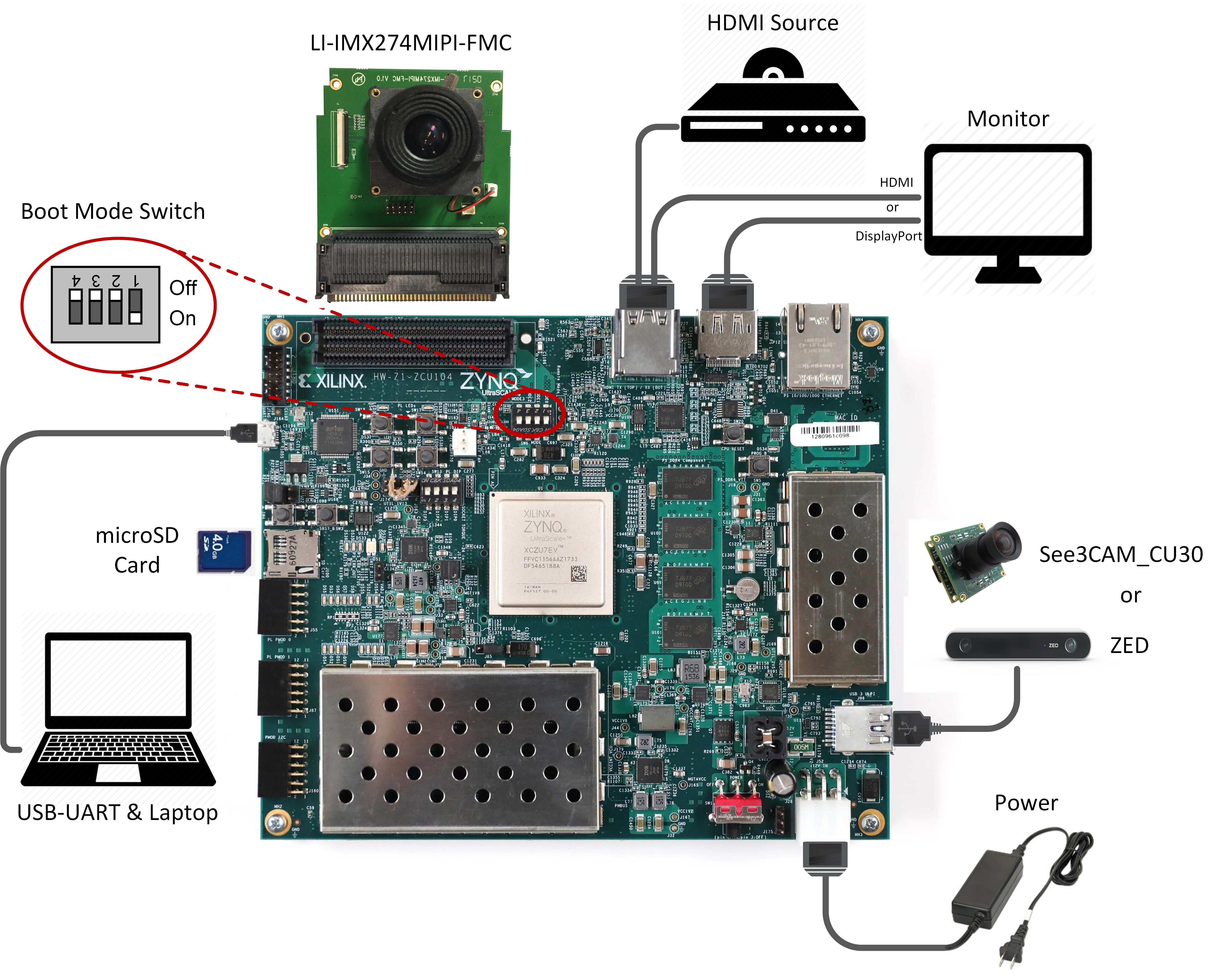
6.1 Board Setup
Required:
- Connect power supply to the 12V power connector.
- Display
- Connect a DisplayPort cable to DisplayPort connector on the board; connect the other end to a monitor OR
- Connect an HDMI cable to HDMI Output (top HDMI connector) on the board; connect the other end to a monitor.
Note: Make sure you only connect either DisplayPort or HDMI Output on the board, not both, otherwise the design might malfunction.
- Connect micro-USB cable to the USB-UART connector; use the following settings for your terminal emulator:
- Baud Rate: 115200
- Data: 8 bit
- Parity: None
- Stop: 1 bit
- Flow Control: None
- Insert SD card (FAT formatted) with pre-built image copied from one of the following directories:
- optical_flow: ./<platform>/sd_card/optical_flow
- stereo: ./<platform>/sd_card/stereo
- filter2d: ./<platform>/sd_card/filter2d
- triple: ./<platform>/sd_card/triple
Optional:
- Connect an HDMI cable to HDMI Input (bottom HDMI connector) on the board; connect the other end to an HDMI source
- Connect the See3CAM_CU30 or ZED USB camera to the USB3 micro-AB connector via the Xilinx USB3 micro-B adapter
- Connect the LI-IMX274MIPI-FMC module to the FMC connector on the board (use the HPC0 connector on the ZCU102)
Note: Vadj needs to be set to 1.2V for correct operation of the daughter card. If the FMC card does not function, please follow the instructions explained in Answer Record AR67308 for rev 1.0 and beyond to check and/or set Vadj.
ZCU102 Jumpers & Switches:
- Set boot mode to SD card
- SW6[4:1]: off,off,off, on
- Configure USB jumpers for host mode. The drawing shows the area on the board near the USB connector.
- J110: 2-3
- J109: 1-2
- J112: 2-3
- J7: 1-2
- J113: 1-2

ZCU104 Jumpers & Switches:
- Set boot mode to SD card
- SW6[4:1]: off,off,off, on
6.2 Extract the design zip files
Download and unzip the reference design zip file matching your silicon version (see Section 4.2).
- For Linux, use the unzip utlity.
- For Windows, make sure that the reference design zip file is unzipped in a directory path which contains no spaces. Use the 7zip utility and follow the steps below. If you need 7zip, get it here 7zip. When prompted to confirm file replace, select ‘Auto Rename’

7 Tool Flow Tutorials
The SDx Development Environment, version 2017.4, must be installed and working on your host computer, either the Linux or the Windows version.
This guide will walk you through the process of building the sample designs. In step 6.2 above, you unzipped your platform files, and noted the exact directory paths.
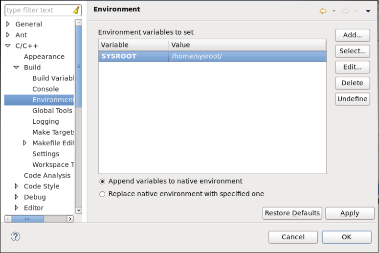
The path to the extracted platform will be needed to tell SDx where your custom platform resides. You need to set the SYSROOT environment variable to point to a directory inside the platform. The platform root directory is abbreviated to <platform> below and needs to be replaced with your local path.
- IMPORTANT: Before starting SDx, set the SYSROOT environment variable to point to the Linux root file system, i.e the sysroot top directory you just unzipped.
Linux: export SYSROOT=<platform>/sw/sysroot
Windows: Start->Control Panel->System->Advanced->Environment Variables Create environment variable SYSROOT with value <platform>\sw\sysroot
The platform ships with five file IO and three live IO design examples demonstrating popular OpenCV functions accelerated on the programmable logic. A fourth live I/O example shows how to combine the other three live I/O designs into one design, allowing the three accelerated functions to reside and run in parallel in the FPGA.
With this release of reVISION the live IO sample design examples are based on GStreamer. See GStreamer The open source GStreamer framework code is included with the reVISION platform, and design examples are built as GStreamer plugins. Code for test applications is provided as well, allowing you to compile apps that will set up and run video pipelines using the plugins. Pipelines may be run using the gst-launch-1.0 utility, or by your own app compiled against the gstreamer libraries. An example test app called gstdemo is provided for each of the platform samples. The four sample <names> are filter2d, optical_flow, stereo, and triple. See the ./workspaces/<name>/gst/apps/<name>. directory for each sample.
A GStreamer plugin is a shared library. In the case of the reVISION sample designs, the GStreamer plugin consists of two linked parts. These "top" and "bottom" parts are separate shared libraries produced by separate project builds. The top part is the GStreamer plugin itself, containing the code for interfacing with the GStreamer framework. See the ./workspaces/<name>/gst/plugins/<name> directory.
The top part links with the bottom part which contains the code for the HW accelerated function(s). This bottom project generates the BOOT.BIN file containing the programmable logic used for the HW function(s). These are SDx projects: See the ./samples/live_IO/<name> directory.
7.1 Build the Live_IO Optical Flow sample application
The following steps are virtually identical whether you are running the Linux or Windows version of SDx.
There is a ./workspaces/... folder structure already set up for the four live_IO samples as part of the platform :
├── workspaces
│   ├── ws_f2d
│   ├── ws_of
│   ├── ws_sv
│   ├── ws_triple
You should copy these workspaces to the directory where you want to work. Look at the optical_flow workspace area supplied with the platform. All files under ./gst/ are supplied exactly as shown. The ./opticalflow directory is the SDx project you will create to build the low level accelerator code - note that you'll create this 'opticalflow' SDx project directly under the ws_of workspace. Note that ./gst/ is also directly under ./ws_of :
├── ws_of
│   ├── gst
│   │   ├── allocators
│   │   │   ├── gstsdxallocator.c
│   │   │   └── gstsdxallocator.h
│   │   ├── apps
│   │   │   └── optical_flow
│   │   │       └── main.c
│   │   ├── base
│   │   │   ├── gstsdxbase.c
│   │   │   └── gstsdxbase.h
│   │   └── plugins
│   │       └── optical_flow
│   │          ├── gstsdxopticalflow.cpp
│   │          └── gstsdxopticalflow.h
│   └── opticalflow
│       └── src
│           ├── optical_flow_sds.cpp
│           └── optical_flow_sds.h
For a given workspace, such as ./ws_of/, the arrangement of these subdirectories must be preserved. This is because the various projects depend on each other in that they need to know the paths to each other's include files and library files. As long as you keep this structure, you're OK - i.e. you may copy the ./ws_of/ tree with everything just as shown, and put it anywhere you want to work.
If you are working on Linux, there is no restriction on where you put these workspaces. Some people may want to work directly in the ./workspaces/ directory under the platform itself, and others may want to copy it elsewhere so that the original area remains untouched.
If you are working on Windows there is a restriction, i.e. file path lengths are restricted to 256 characters. The Xilinx build process creates some very deep directory structures with long names as it goes through the build process. You are advised, therefore, to keep the path to the workspace as short as possible. E.g. C:\ws_of\...
- Start SDx and select workspace ./ws_of. Make sure you use the same shell to run SDx as the one where you have set $SYSROOT.
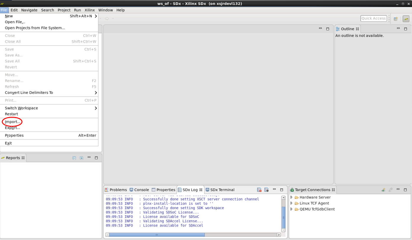
- Close the Welcome screen and select 'File'→'Import'→'General'→'Existing Projects into Workspacel'→'Next'.

- In the Import dialog, to the right of 'Select root directory', click 'Browse'.
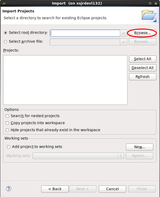
- By default you're already in the directory you want ./workspaces/ws_of, just click 'OK'.

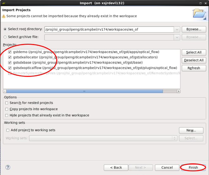
- You should see a list of projects, with gstdemo, gstsdxallocator, gstsdxbase, and gstopticalflow selected, click 'Finish'.
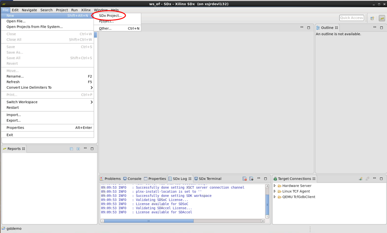
- Back at the main window, the four imported projects appear in the Project Explorer pane. Now select 'File'→'New'→'SDx Project'... from the menu bar.
- This brings up the Project Type dialog box, with Application Project selected, click 'Next'.

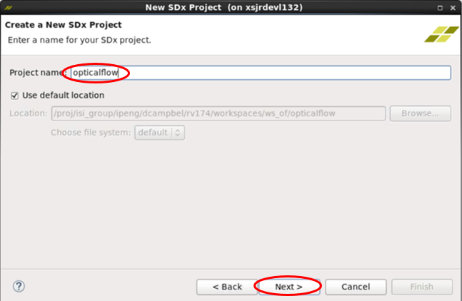
- In the 'Create a New SDx Project' dialog, enter Project name 'opticalflow', click 'Next'.
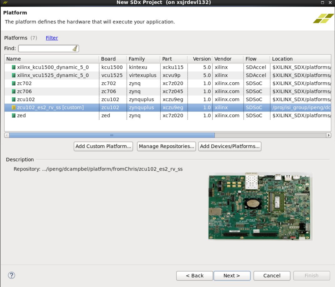
- In the Platform dialog, click 'Add Custom Platform', find your way to the top directory where you unzipped the reVISION platform, called, for example, zcu102_rv_ss. Click 'OK'.


- Back in the Platform dialog, the new platform appears in the list, but is not selected. Select it, then click 'Next'.

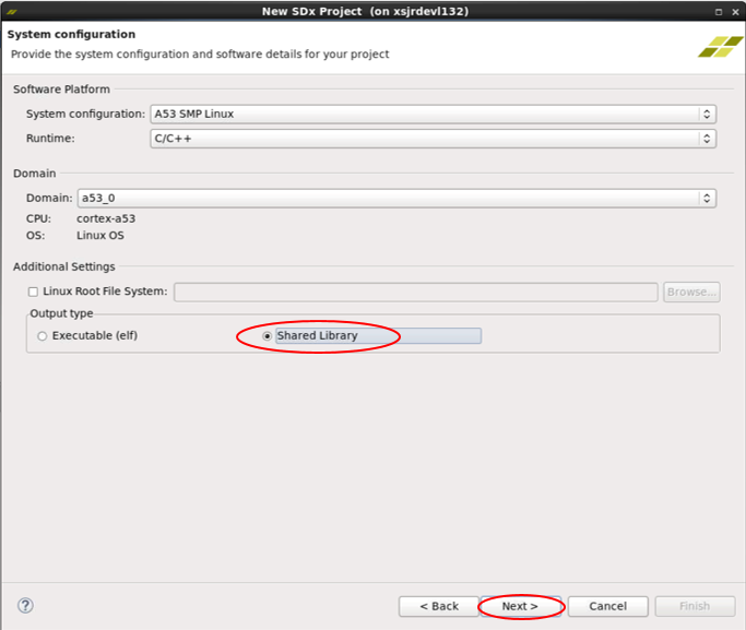
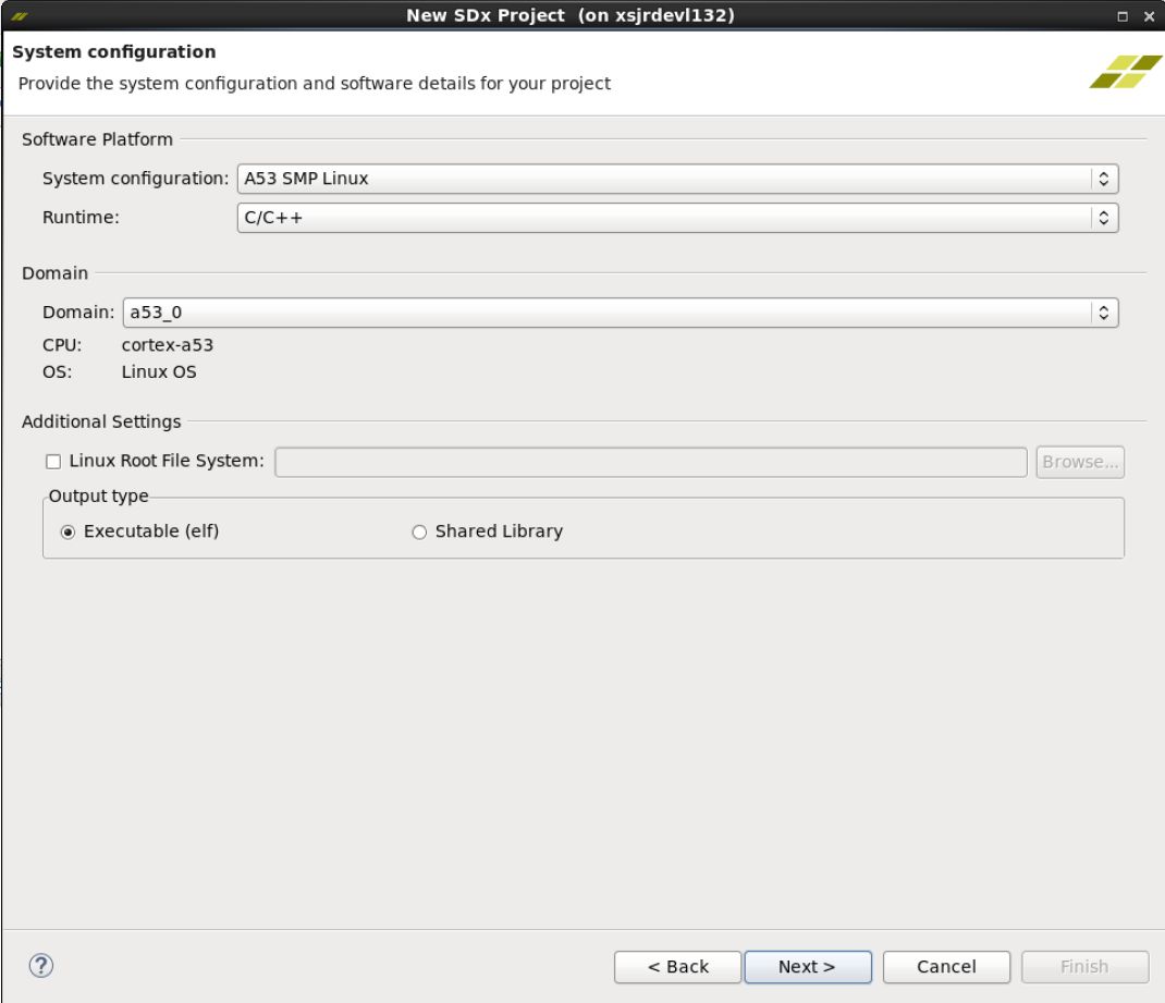
- In the System configuration dialog, under Output type, select 'Shared Library', click 'Next'.
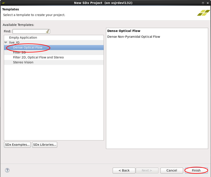
- In the Templates dialog, under live_IO select Dense Optical Flow and click 'Finish'.
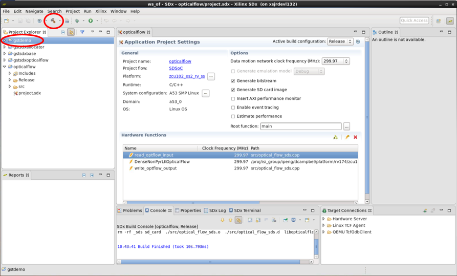
- Back again at the main window, the new project 'opticalflow' appears under the four imported projects appear in the Project Explorer pane.
- Switch the 'Active Build Configuration' for the opticalflow project to Release. Note that three routines are marked as Hardware Functions.

- Build the opticalflow project - do this by clicking right and choosing Build Project, or by clicking the 'hammer' icon.
- In the small Build Project dialog that opens, you may hit the "Run in Background" button. That causes the small dialog box to disappear, though you can still see a progress icon in the lower right part of the GUI, showing that work is in progress. Select the Console tab in the lower central pane of the GUI to observe the steps of the build process as it progresses. The build process may take tens of minutes, up to several hours, depending on the power of your host machine, whether you are running on Linux or Windows, and of course the complexity of your design. By far the most time is spent processing the routines that have been tagged for realization in hardware - note the "HW functions" window in the lower part of the SDx Project Settings pane. In our example above, the routines read_optflow_input, DenseNonPyrLKOpticalFlow, and write_optflow_output are tagged to be built in hardware. The synthesis of the C code found in these routines into RTL, and the Placement and Routing of that RTL into the programmable logic in the Zynq MPSoC, are the steps that take most of the time.

- Once the Build completes, you will find an sd_card directory has been created containing these files you'll need to transfer to your SD card
- ./workspaces/ws_of/opticalflow/Release/sd_card/BOOT.BIN
- ./workspaces/ws_of/opticalflow/Release/sd_card/libopticalflow.so
- ./workspaces/ws_of/opticalflow/Release/sd_card/image.ub
- ./workspaces/ws_of/opticalflow/Release/sd_card/video_cmd
- Now that the "bottom" shared library is built, you may build the "top" part, that will be linked with the bottom library. Now select the gstdemo project, and build it. Doing this will build all four of the gst--- projects.
- This entire process should take only a few minutes, and creates these libraries and executable
- ./workspaces/ws_of/gst/allocators/Debug/libgstsdxallocator.so
- ./workspaces/ws_of/gst/base/Debug/libgstsdxbase.so
- ./workspaces/ws_of/gst/plugins/optical_flow/Debug/libgstsdxopticalflow.so
- ./workspaces/ws_of/gst/apps/optical_flow/Debug/gstdemo
7.2 Build the Stereo, the Filter2D, and the Triple sample applications
- The Stereo, Filter2D and the Triple project may be created and built in the same way just explained for the Optical Flow project. The steps are very similar.
- Launch SDx, starting in the appropriate workspace directory./workspaces/ws_sv,
./workspaces/ws_f2d or
./workspaces/ws_triple, respectively. - In the Templates dialog, select 'Stereo Vision', 'Filter2D', or 'Filter2D, Optical Flow and Stereo', respectively.
- All the other steps are analogous.
7.3 Build the File IO sample applications
- Start SDx and create a new workspace. Make sure you use the same shell to run SDx as the one where you have set $SYSROOT.
- Close the Welcome screen and select 'File' → 'New' → 'SDx Project'... from the menu bar. Select Application Project and click 'Next'. This brings up the Create a New SDx Project dialog box. Enter a name for project (e.g. “bil_fil” which stands for bilateral filter), click 'Next'.

- Leave the "Use default location" box checked, hit Next>, this opens the "Platform" page.
- Select the platform. The very first time you do this for a new workspace, you must hit Add Custom Platform (as explained in the Live_IO section 6.3.1) and select the custom platform.
- Select your custom platform e.g. "zcu102_es2_rv_ss (custom)", hit 'Next', this opens the "System configuration" page.
- Leave everything as is, hit Next>, this opens the "Templates" page.
- Select “bilateral – File I/O” from the set of templates and click on “Finish”.

- The dialog box closes, and you now see the SDx Project Settings pane in the center of the SDx GUI. Notice the progress bar in the lower right border of the pane, saying "C/C++ Indexer" - wait a few moments for this to finish. Locate the "Active build configuration:" in the upper right corner of the pane, which says "Debug" - click it and select Release. Your window should now look something like this:

- In the left hand "Project Explorer" pane, select the bil_fil project, click right on it, then select Build Project. The "Hammer" icon in the menu bar also performs "Build Project". In the small Build Project dialog that opens, you may hit the "Run in Background" button. That causes the small dialog box to disappear, though you can still see a progress icon in the lower right part of the GUI, showing that work is in progress. Select the Console tab in the lower central pane of the GUI to observe the steps of the build process as it progresses. The build process may take tens of minutes, up to several hours, depending on the power of your host machine, whether you are running on Linux or Windows, and of course the complexity of your design. By far the most time is spent processing the routines that have been tagged for realization in hardware - note the "HW functions" window in the lower part of the SDx Project Settings pane. “bilateralFilter” is listed as a function tagged to be moved to hardware.
- Once the Build completes, you will find an sd_card directory has been created at
- .\<workspace>\bil_fil\Release\sd_card
- In order to run the function on the board, mount the SD card on the board and power it on.
- At the prompt, go to the directory “/media/card”. Use the following command: cd /media/card
- Run the executable using the following command: ./bil_fil.elf im0.jpg
- If the run is successful, the following text appears at the terminal:
sigma_color: 7.72211 sigma_space: 0.901059 elapsed time 9133271 Minimum error in intensity = 0 Maximum error in intensity = 1 Percentage of pixels above error threshold = 0.00168789 Count: 35
- Follow the same procedure for other file I/O samples – Harris corner detection, optical flow, stereo block matching and warpTransform.
8 Run the Application
To use the GStreamer plugins, a video pipeline that includes them must be set up and launched. The command line utility gst-launch-1.0 may be used to do this. Use your laptop connected to the target board over a serial terminal emulator, interacting with the system via a standard Linux console session. See section 6.1. You may construct video pipeline graphs consisting of one or more sources, zero, one or more accelerators, and one sink. GStreamer is responsible for initializing the capture, memory-to-memory, and display pipelines as well as managing the video buffer flow through the pipeline stages.
The gst-launch utility is really a debugging tool. The other way to set up and launch your plugins is with a compiled application that sets up and runs the pipeline using API calls to the GStreamer libraries. The sample code is provided for test apps that do this. See the ./gst/apps/<name> folder for each of the live_IO samples.
The HDMI and MIPI input channels are themselves hardware pipelines that must be configured. This task is done by the video_cmd utility, run once before starting up a pipeline that uses that video input. The video_cmd utility is present on the sd_card directory. It is needed only when the MIPI or HDMI input channels are used.
8.1 Run the live_IO sample applications
- The "bottom" project containing the HW accelerated code is an SDx project, e.g. ./ws_f2d/filter2d. When it completes, it creates an sd_card image with files you need to copy to your SD card you'll use on the target board.
- Before copying the sd_card directory to the SD card, the "top" gst libraries and main demo program must be copied to the sd_card directory. The following sections list the exact files for each case.
- For the stereo and triple case (because it includes stereo) you will also need the camera configuration file on the sd_card. (see below: "Particularities about the Stereo demo").
filter2d case
After building the "bottom" library, your sd_card directory will contain these files:
- ./ws_f2d/filter2d/Release/sd_card/image.ub
- ./ws_f2d/filter2d/Release/sd_card/BOOT.BIN
- ./ws_f2d/filter2d/Release/sd_card/libfilter2d.so
- ./ws_f2d/filter2d/Release/sd_card/video_cmd
- ./ws_f2d/gst/plugins/filter2d/Debug/libgstsdxfilter2d.so
- ./ws_f2d/gst/base/Debug/libgstsdxbase.so
- ./ws_f2d/gst/allocators/Debug/libgstsdxallocator.so
- ./ws_f2d/gst/apps/filter2d/Debug/gstdemo.
opticalflow case
After building the "bottom" library, your sd_card directory will contain these files:
- ./ws_of/opticalflow/Release/sd_card/image.ub
- ./ws_of/opticalflow/Release/sd_card/BOOT.BIN
- ./ws_of/opticalflow/Release/sd_card/libopticalflow.so
- ./ws_of/opticalflow/Release/sd_card/video_cmd
- ./ws_of/gst/plugins/optical_flow/Debug/libgstsdxopticalflow.so
- ./ws_of/gst/base/Debug/libgstsdxbase.so
- ./ws_of/gst/allocators/Debug/libgstsdxallocator.so
- ./ws_of/gst/apps/optical_flow/Debug/gstdemo.
stereo case
After building the "bottom" library, your sd_card directory will contain these files:
- ./ws_sv/stereo/Release/sd_card/image.ub
- ./ws_sv/stereo/Release/sd_card/BOOT.BIN
- ./ws_sv/stereo/Release/sd_card/libstereo.so
- ./ws_sv/stereo/Release/sd_card/video_cmd
- ./ws_sv/gst/plugins/stereo/Debug/libgstsdxstereo.so
- ./ws_sv/gst/base/Debug/libgstsdxbase.so
- ./ws_sv/gst/allocators/Debug/libgstsdxallocator.so
- ./ws_sv/gst/apps/stereo/Debug/gstdemo.
triple case
After building the "bottom" library, your sd_card directory will contain these files:
- ./ws_triple/triple/Release/sd_card/image.ub
- ./ws_triple/triple/Release/sd_card/BOOT.BIN
- ./ws_triple/triple/Release/sd_card/libtriple.so
- ./ws_triple/triple/Release/sd_card/video_cmd
- ./ws_triple/gst/plugins/filter2d/Debug/libgstsdxfilter2d.so
- ./ws_triple/gst/plugins/optical_flow/Debug/libgstsdxopticalflow.so
- ./ws_triple/gst/plugins/stereo/Debug/libgstsdxstereo.so
- ./ws_triple/gst/base/Debug/libgstsdxbase.so
- ./ws_triple/gst/allocators/Debug/libgstsdxallocator.so
- ./ws_triple/gst/apps/triple/Debug/gstdemo.
- Copy the whole sd_card directory to your SD card, and insert it in the SD card slot on your target board.
- Power on the board; make sure the large "INIT_B" LED and the "DONE" LED next to it go green after a few seconds.
- Control the system from your computer: start a terminal session using TeraTerm, PuTTY or the like. See section 6.1. With the USB-UART cable connected and the board powered up, you can locate the COM port that is responsive. You'll see several pages of Linux bootstrap and debug messages scroll by, finishing at the linux command line prompt.
- cd over to directory /media/card . This directory contains all the files you copied to your SD card.
# cd /media/card
- Copy the shared libraries where they need to go.
- filter2d case:
# cp libfilter2d.so /usr/lib
# cp libgstsdxfilter2d.so /usr/lib/gstreamer-1.0
# cp libgstsdxbase.so /usr/lib/gstreamer-1.0
# cp libgstsdxallocator.so /usr/lib/gstreamer-1.0
- opticalflow case:
# cp libopticalflow.so /usr/lib
# cp libgstsdxopticalflow.so /usr/lib/gstreamer-1.0
# cp libgstsdxbase.so /usr/lib/gstreamer-1.0
# cp libgstsdxallocator.so /usr/lib/gstreamer-1.0
- stereo case:
# cp libstereo.so /usr/lib
# cp libgstsdxstereo.so /usr/lib/gstreamer-1.0
# cp libgstsdxbase.so /usr/lib/gstreamer-1.0
# cp libgstsdxallocator.so /usr/lib/gstreamer-1.0
- triple case:
# cp libtriple.so /usr/lib
# cp libgstsdxfilter2d.so /usr/lib/gstreamer-1.0
# cp libgstsdxopticalflow.so /usr/lib/gstreamer-1.0
# cp libgstsdxstereo.so /usr/lib/gstreamer-1.0
# cp libgstsdxbase.so /usr/lib/gstreamer-1.0
# cp libgstsdxallocator.so /usr/lib/gstreamer-1.0
Media pipeline initialization
Use the video_cmd utility to list the available video sources and to configure the media pipeline. This needs to be done before running the gstreamer demo app or the gst-launch utility.
- To list all available video sources, their source IDs and corresponding video nodes:
# video_cmd -S
    VIDEO SOURCE        ID         VIDEO DEVNODE
    MIPI CSI2 Rx        0       /dev/video3
      HDMI Input        1       /dev/video2
      USB Webcam        2       /dev/video4
Virtual Video De        3       /dev/video0
- Note: The output depends on the peripherals connected to the board and can be different in your case. The middle column shows the source ID which is needed for the next step to initialize the media pipeline (-s switch).
The MIPI, HDMI and vivid video sources support the YUY2 and UYVY pixel formats. For USB, the supported pixel format depends on the camera firmware e.g. the e-con USB camera only supports UYVY whereas the ZED stereo camera supports only YUYV (which is identical with YUY2). Make sure you set the input parameters correctly when configuring the media pipeline.
- Configure MIPI media pipeline for 1920x1080 resolution and YUY2 pixel format:
# video_cmd -s 0 -i 1920x1080@YUY2 -X
- -s 0 is the input source ID, in this case MIPI CSI
- -i 1920x1080@YUY2 means the MIPI source will be set up for 1080p resolution and YUY2 format
- -X causes video_cmd to exit immediately after setting up MIPI.
- returns video node that corresponds to the input ID selected by -s. The video node needs to be passed to the v4lsrc plugin via the device property
- Configure HDMI media pipeline for 1920x1080 resolution and UYVY pixel format:
# video_cmd -s 1 -i 1920x1080@UYVY -X
- -s 1 is the input source ID, in this case is HDMI
- -i 1920x1080@UYVY means the MIPI source will be set up for 1080p resolution and UVYV fomat
- -X causes video_cmd to exit immediately after setting up HDMI.
- returns video node that corresponds to the input ID selected by -s. The video node needs to be passed to the v4lsrc plugin via the device property
Display controller initialization
Use the video_cmd utility to initialize the display controller. The command should be run in the background as the display mode will otherwise be reset to its original value after video_cmd exits. This needs to be done before running the gstreamer demo app or the gst-launch utility.
- Configure DP display controller
# video_cmd -d 0 -o 1920x1080 &&
- -d 0 is the display ID for DP
- -o 1920x1080 means the display resolution will be set to 1920x1080
- Configure HDMI display controller
# video_cmd -d 1 -o 1920x1080 &&
- -d 1 is the display ID for HDMI
- -o 1920x1080 means the display resolution will be set to 1920x1080
Gstreamer application
To create and run the gstreamer pipeline, you can either use the gst demo applications that are compiled from source or you can use the prebuilt gst-launch utility.
- Use your compiled demo program:
# ./gstdemo
- All the demo programs use HDMI output, via the mixer.
- The filter2d demo uses HDMI input.
- The opticalflow demo uses the MIPI input
- The stereo demo used the USB "ZED" stereo camera input
- The triple demo uses all of the above
- Here is a gst-launch command to run the filter2d pipeline, from MIPI, 1920x1080, YUY2, to HDMI output via mixer plane 26.
gst-launch-1.0 \
    v4l2src device=/dev/video3 io-mode=dmabuf ! \
    "video/x-raw, width=1920, height=1080, format=YUY2" ! \
    sdxfilter2d filter-preset=4 filter-mode=1 ! queue ! \
    kmssink driver-name=xilinx_drm_mixer plane-id=26 sync=false
- Here is a gst-launch command to run the opticalflow pipeline, from HDMI, 1920x1080, YUY2, to HDMI output via mixer plane 26.
gst-launch-1.0 \
    v4l2src device=/dev/video2 io-mode=dmabuf ! \
    "video/x-raw, width=1920, height=1080, format=YUY2" ! \
    sdxopticalflow filter-mode=1 ! queue ! \
    kmssink driver-name=xilinx_drm_mixer plane-id=26 sync=false
- Here is a gst-launch command to run the stereo pipeline, from USB, 3840x1080 side-by-side input, YUY2, 1920x1080 output to HDMI via mixer plane 26. You must substitute your camera serial number for the config-filename property. See section below on "Particuliarities about the Stereo Demo".
gst-launch-1.0 \
    v4l2src device=/dev/video4 io-mode=dmabuf ! \
    "video/x-raw, width=3840, height=1080, format=YUY2" ! \
    sdxstereo filter-mode=1 config-filename=/media/card/SN12263.conf ! queue ! \
    kmssink driver-name=xilinx_drm_mixer plane-id=26 sync=false
- Here is an alternate way of running filter2d, with frames-per-second display enabled. Notice the output pipe stage is 'fpsdisplaysink' and that the 'kmssink...." string we used before is a property of fpsdisplaysink called 'video-sink'.
gst-launch-1.0 \
    v4l2src device=/dev/video3 io-mode=dmabuf ! \
    "video/x-raw, width=1920, height=1080, format=YUY2" ! \
    sdxfilter2d filter-preset=4 filter-mode=1 ! queue ! \
    fpsdisplaysink video-sink="kmssink driver-name=xilinx_drm_mixer plane-id=26" sync=false text-overlay=false -v
8.2 Gstreamer elements
These pipelines are using the elements v4l2src, sdxfilter2d (or sdxopticalflow, or sdxstereo), queue, and kmssink. You may display properties and other info about any of these elements using the gstreamer utility gst-inspect-1.0.
v4l2src
# gst-inspect-1.0 v4l2src
- You will see a lot of information. Of interest to us here is the v4l2src "device" property that is set in each of the above commands to select the video source
- /dev/video2 is HDMI
- /dev/video3 is MIPI
- /dev/video4 is US
- The io-mode property
- 4 is "dmabuf" - it means that we will not have to copy images in between pipe stages - the frames are passed by reference.
- Following the first '!' character is an expression "video/x-raw, ....". This is a "capabilities filter" that informs the v4l2src element which of the many formats it supports are suitable for the downstream pipe element. Specifically:
- "raw" video (uncompressed)
- width and height
- pixel format - YUY2 is 16 bit per pixel 4:2:2 with 'Y' on the LOW byte of each word. UYVY is also 16 bit 4:2:2, with 'Y' on the HIGH byte of each word.
queue
This is not strictly necessary, but using it will give better performance - i.e. the highest possible frame rate.
kmssink
To inspect the kmssink plugin:
# gst-inspect-1.0 kmssink
- property 'driver-name'
- 'xilinx_drm_mixer' means HDMI output (via the video mixer)
- 'xilinx_drm' means DP output
- property 'plane-id'
- if you are using xilinx_drm_mixer (HDMI output)
- '26' is a YUY2 plane
- '27' is a YUY2 plane
- '28' is a UYUV plane
- if you are using xilinx_drm (DP output)
- '25' supports a number of RGB
- '26' supports YUY2 and UYVY
- if you are using xilinx_drm_mixer (HDMI output)
sdx<accelerator>
To inspect the sdxfilter2d plugin:
# gst-inspect-1.0 sdxfilter2d
- property 'filter_mode'
- 1: use HW acceleration
- 0: use SW (the filter2d code executes entirely on the ARM processor)
- property 'filter_preset'
- 1 - 10 select a number of preset filters. The example uses '4' which is the 'emboss' or edge enhancement filter.
- property 'coefficients'
- Array with a 3x3 coefficients matrix e.g. coefficients="<<0,0,0>,<0,-1,0>,<0,0,0>>"
To inspect the sdxopticalflow plugin:
# gst-inspect-1.0 sdxopticalflow
- property 'filter_mode'
- 1: use HW acceleration
- 0: use SW (the optical flow code executes entirely on the ARM processor)
To inspect the sdxstereo plugin:
# gst-inspect-1.0 sdxstereo
- property 'filter_mode'
- 1: use HW acceleration
- 0: use SW (the optical flow code executes entirely on the ARM processor)
- property 'config-filename'
- This is how you specify the ZED camera configuration file, which must be present on the SD card. See the notes below.
8.3 Particularities about the Stereo demo
The stereo vision demo is special in several ways. First, you MUST use the ZED stereo camera connected to the USB video input. Second, and particular to this app, the width of the input image resolution is twice the width of the output resolution. The input consists of two images side-by-side, the synchronized left and right stereo input supplied by the camera. Two cases are possible: 2560x720 in to 1280x720 out, and 3840x1080 in to 1920x1080 out. The default 3840x2160 output resolution is not supported by the Stereo Vision app.
The other special thing about this app is that a configuration file must be used that corresponds to the camera you have connected to your system . Each StereoLabs ZED camera has a unique parameters file associated with it. This text file comes from StereoLabs, and must be present on the SD Card for the Stereo Vision demo to work properly. You need the file unique to your camera, identified by its Serial Number (found on the ZED camera box and also on a black tag near the USB plug of the ZED camera itself). This number will be, e.g., S/N 000012345. The parameter file for that camera would be named SN12345.conf. To download your parameter file, enter this URL into your browser:
http://calib.stereolabs.com/?SN=12345 (using your serial number in place of 12345)
This will download your configuration file to your computer.
The stereo block-matching algorithm calculates depth based on binocular parallax, similar to the way human eyes perceive depth. The depth map is coded in false colors. Objects far away appear deep blue. Closer and closer objects appear in rainbow succession green, yellow, orange, red, purple and finally white at about two feet from the camera in the 720p case, and about five feet away in the 1080p case. Any object closer than that cannot be tracked, and smooth areas with no texture in the image cannot be tracked, and show up as black. Areas with a lot of detail (especially with lots of vertical edges) are tracked best. It is normal that a large area on the left is black - this is 128 pixels wide, representing the range of the horizontal search for best match between the right and left binocular images.
9 Platform Details
9.1 Vivado Hardware Design
The Vivado hardware design is packaged inside the DSA located at zcu10[2|4]_[es2_]rv_ss/hw/zcu102_[es2_]rv_ss.dsa. The DSA also includes the hpfm file that describes the available AXI interfaces, clocks, resets, and interrupts. To open the hardware design in Vivado, run the following command from the tcl console:
% open_dsa zcu10[2|4]_[es2_]rv_ss/hw/zcu10[2|4]_[es2_]rv_ss.dsa
9.2 PetaLinux BSP
The PetaLinux BSP is located at zcu10[2|4]_[es2_]rv_ss/sw/petalinux_bsp. The hdf file exported from the corresponding Vivado project (see 9.1) is available in the project-spec/hw-description/ subfolder inside to the PetaLinux BSP. To configure and build the PetaLinux BSP, run the following commands:
% petalinux-config --oldconfig
% petalinux-build
- bl31.elf
- pmufw.elf
- u-boot.elf
- zynqmp_fsbl.elf
- image.ub
The generated sysroot is located at build/tmp/sysroots/plnx_aarch64.
Note: The tmp directory might relocated to a different folder especially if your petalinux project is located on a NFS mount. Please check your petalinux configuration.
9.3 Video Command Line Utility
The Xilinx video_cmd utility is used to initialize the media pipeline of an associated V4L2 capture device. A prebuilt version of this utility is available at zcu10[2|4]_[es2_]rv_ss/sw/a53_linux/image/video_cmd and will be automatically placed in the sd_card folder of the generated SDx project.
The video_cmd and video_lib sources are provided as XSDK projects and are located at zcu10[2|4]_[es2_]rv_ss/workspaces/ws_video. Perform the following steps to build the application using the SDx GUI:
- Make sure the SYSROOT environment variable is set correctly before starting SDx (see design example tutorials for details).
- Start SDx and select the zcu10[2|4]_[es2_]rv_ss/workspaces/ws_video directory as your workspace.
- From the SDx menu bar, select 'File -> Import -> General -> Existing Projects into Workspace'. Click 'Next'.
- In the 'Import Project' dialog, browse to the workspace root directory at zcu102_[es2_]rv_ss/workspaces/ws_video. Make sure the video_lib and video_cmd projects are checked and click 'Finish'.
- Right-click the newly added video_cmd project in the 'Project Explorer' and select 'Build Project'. The video_cmd output product will be placed inside the Debug or Release subfolder depending on the chosen build configuration.
10 Other Information
10.1 Known Issues
- SDSoC accelerator code runs very slowly in pure software implementation when Debug configuration is used.
Solution: Set project build configurations to Release which sets sdsoc compiler to optimize most (-O3). - Running the filter2d accelerator in SW mode with UYVY input format selected results in a green image
Solution: Run the filter2d accelerator in HW mode or set the input format to YUYV in SW mode (see 10.2 Limitations) - The following message is displayed at the end of the boot process
/bin/autologin: line1: -e: command not found
Solution: The message is benign and can be ignored - The following error message is shown when starting a gstreamer pipeline for the first time:
(gst-plugin-scanner:2573): GStreamer-WARNING : Failed to load plugin '/usr/lib/gstreamer-1.0/libgstomx.so': /usr/lib/gstreamer-1.0/libgstomx.so: undefined symbol: gst_omx_h265_enc_get_type
Solution: The message is benign and can be ignored - The following error message may appear when starting a gstreamer pipeline:
(gst-plugin-scanner:2573): GStreamer-WARNING : Failed to load plugin '/usr/lib/gstreamer-1.0/libgstsdxbase.so': /usr/lib/gstreamer-1.0/libgstsdxbase.so: undefined symbol: gst_sdx_allocator_new
Solution: The message is benign and can be ignored - The following error message is shown when compiling the SDx project:
WARNING: [DMAnalysis 83-4492] Unable to determine the memory attributes passed to _mapx_mat.data of function w1_xf_remap at /home/workspaces/ws_sv/stereo/src/stereo_sds.cpp:257, please use mem_attribute pragma to specify
Solution: The message is benign and can be ignored - When utilizing an HDMI monitor it is sometimes necessary to run the following command before launching the examples. This is because the HDMI display is not initialized. The
Solution: Run the command with the correct resolution of your display "modetest -M xilinx_drm_mixer -s 33:3840x2160@AR24" - When running the sdxstereo plugin, upon termination, you may sometimes see the message ERROR: application has performed illegal memory access and is being terminated.
Solution: This error comes from the sdxstereo plugin, and will be corrected in a future release. - When attempting to terminate the sdx--- plugins, you may sometimes experience a hang of the linux OS. No message appears and you do not come back to the linux prompt.
Solution: This error comes from the sdx--- plugins, and will be corrected in a future release. - The frmbuf_wr IP in the catalog does not flush pending AXI transactions upon halt, hence stale transactions are posted when re-starting the core or when switching between resolutions. This affects only the ZCU104 design.
Solution: A patched version of the frmbuf_wr IP is provided as local IP for the ZCU104 design so the user does not see this artifact. The IP will be fixed in the catalog in a future release.
10.2 Limitations
- Do not connect a DisplayPort cable and HDMI Tx at the same time.
- Make sure the DisplayPort or HDMI Tx cable is plugged in when you power on the board.
- DP-to-HDMI adapters are not supported, see AR 67462
- HDMI Rx:
- Does not support YUV 4:2:0 input.
- Does not support HDCP encrypted input.
- Does not support hotplug or dynamic resolution changes while the application is running.
- The provided image signal processor (ISP) pipeline does not include any auto algorithms. The IMX274, gamma, and color correction controls have to be adjusted manually based on the surrounding environment.
- The filter2d live IO sample does not support the UYVY pixel format, make sure you select YUY2 in your application. You will not be able to use the e-con USB camera with this sample.
- The optical_flow live IO sample does not have a software implementation of the algorithm, only the hardware optimized implementation is available.
- SDSoC does not support “Estimate Performance” for the xfopenCV library and in general for all the C++ templates (the part of Performance Estimation flow not yet supported is the estimate of software performance for function templates). Once the HLS estimate of HW resources pops up, the Ethernet P2P communication process between the SDSoC GUI and the board stalls forever and no error message is displayed.
11 Support
To obtain technical support for this reference design, go to the:
- Xilinx Answers Database to locate answers to known issues
- Xilinx Community Forums to ask questions or discuss technical details and issues. Please make sure to browse the existing topics first before filing a new topic. If you do file a new topic, make sure it is filed in the sub-forum that best describes your issue or question e.g. Embedded Linux for any Linux related questions. Please include "ZCU102 reVISION" and the release version in the topic name along with a brief summary of the issue.
12 References
Additional material that is not hosted on the wiki:
- Base TRD User Guide: Contains information about system, software and hardware architecture which is similar to the reVISION platform.
- Xilinx OpenCV User Guide: Contains detailed description of Xilinx OpenCV functions and file I/O design examples.
- Xilinx Fast OpenCV on Github
- Xilinx Linux Drivers:
© Copyright 2019 - 2022 Xilinx Inc. Privacy Policy