Booting via Serial ATA (SATA) on ZCU102 Evaluation Platform
This wiki page outlines the general workflow required to configure the ZCU102 evaluation platform to boot via the serial ATA (SATA) interface available on the Zynq UltraScale+ MPSoC device.
Table of Contents
Introduction
In general, these steps follow those outlined on the main landing page of the Xilinx wiki. Where needed, alterations to the workflow are noted. These instructions are based on the 2018.1 release. Changes to this workflow may be required for future releases. These steps have been tested on ZCU102 - REV1.0 Prod-Silicon Board, Rev1.0 ES2 Board, and, RevD2 Prod Board.
SATA is enabled by default in Vivado 2018.1 Board files. Same holds true for the Default ZCU102 Board Template HDF used in Petalinux 2018.1 and SDK 2018.1.
Refer UG1144 Petalinux Tools Reference Guide, to create a PetaLinux Project using appropriate BSP projects
Download and Build U-Boot exactly as described here - http://www.wiki.xilinx.com/Build+U-Boot#Zynq
Modify U-boot config to enable sataboot command
Copy the Boot Image BOOT.BIN to SD Card.

If the scsi scan command reports an attached hard disk, perform the remainder of the boot by using the following command:
At this point you ca see that Linux starts loading and Kernel logs appear on the Terminal.
Note: The next set of steps are optional, which show how SATA is enabled in Vivado and how Boot images can be created using SDK.
Build the Device Tree Compiler exactly as described here - http://www.wiki.xilinx.com/Build+Device+Tree+Compiler+%28dtc%29
Use ATf (bl31.elf) from PetALinux Project or Build ARM Trusted Firmware exactly as described here - http://www.wiki.xilinx.com/Build+ARM+Trusted+Firmware+%28ATF%29
This .BIF file should be updated to reflect the full path on disk for each of the components. After processing the .BIF file, BootGen will create a BOOT.BIN file. Copy the BOOT.BIN to SD card, follow steps from Configuring the Board.
SATA is enabled by default in Vivado 2018.1 Board files. Same holds true for the Default ZCU102 Board Template HDF used in Petalinux 2018.1 and SDK 2018.1.
Build Images using PetaLinux 2018.1
- Download and Install PetaLinux - 2018.1.
- Based on the Evaluation board, download the ZCU102 BSP (prod-silicon) or ZCU102 Rev 1 ES2.
Refer UG1144 Petalinux Tools Reference Guide, to create a PetaLinux Project using appropriate BSP projects
petalinux-create -t project -s <BSP_Project>
- SATA is enabled by default in the Board templates used in PetaLinux BSP.
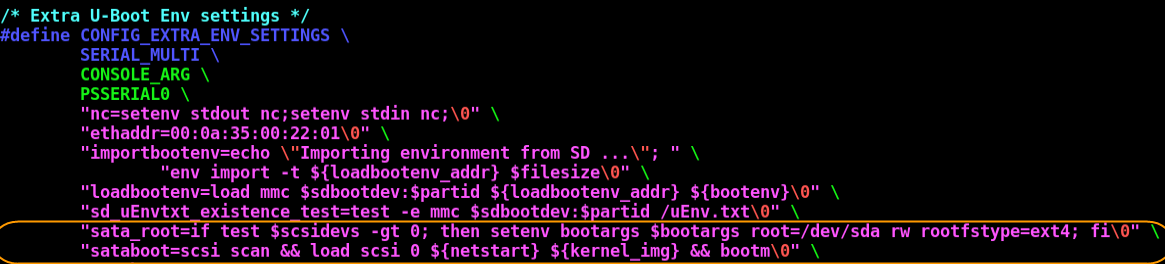
In PetaLinux Project, add following in platform-auto.h file to enable sataboot from u-boot.
cd <petalinux-project>
"sata_root=if test $scsidevs -gt 0; then setenv bootargs $bootargs root=/dev/sda rw rootfstype=ext4; fi\0" \
"sataboot=scsi scan &&&& load scsi 0 ${netstart} ${kernel_img} &&&& bootm\0" \
<Petalinux-Project>/project-spec/meta-plnx-generated/recipes-bsp/u-boot/configs/platform-auto.h
- The first line sets bootargs to instruct the Linux kernel to find the root filesystem located on the SATA disk. This has no effect for default PetaLinux configuration as the default RootFS for PetaLinux is INITRAMFS. INITRAMFS (Initial RAM File System) is the successor of initrd. It is a cpio archive of the initial file system that gets loaded into memory during the PetaLinux startup process. The Linux kernel mounts it as RootFS and starts the initialization process.
- The second line is to enable sataboot environment settings for u-boot.
- Save and exit.
- build PetaLinux project using petalinux-build command.
- While PetaLinux builds, create an EXT (preferably EXT4) partition in the SATA disk.
- Once built successfully, copy image.ub file from <petalinux-project>/images/linux/image.ub to EXT Partition of SATA disk.
Use following command to Create a Boot Image with partitions viz. FSBL, U-boot, PMU Firmware (PMUFW), and ATF (bl31.elf).
cd <petalinux-project>/
petalinux-package --boot --fsbl images/linux/zynqmp_fsbl.elf --u-boot
- Copy the BOOT.BIN image to SD Card.
Build Images using PetaLinux 2016.4
Refer UG1144 Petalinux Tools Reference Guide, to create a PetaLinux Project using appropriate BSP projects
petalinux-create -t project -s <BSP_Project>
- build PetaLinux project using petalinux-build command.
- While PetaLinux builds, create an EXT (preferably EXT4) partition in the SATA disk.
- Once built successfully, copy Image file (<petalinux-project>/images/linux/Image) and the device tree file (<petalinux-project>/images/linux/system.dtb) to EXT Partition of SATA disk.
U-Boot 2016.4
Download and Build U-Boot exactly as described here - http://www.wiki.xilinx.com/Build+U-Boot#Zynq
Modify U-boot config to enable sataboot command
Build Boot Image for 2016.4
Use FSBL,PMU firmware (PMUFW), ATF (bl31.elf) from PetaLinux project, and u-boot.elf from U-boot source tree, and create Boot Image by following steps from Building the Final Boot Image.Copy the Boot Image BOOT.BIN to SD Card.
Configuring the Board
Attaching the Hard Disk
- Connect a Serial ATA (SATA) data cable from the SATA connector (P9) to your hard disk.
- Connect a 4-pin ATX-to-SATA power cable from the 4-pin ATX power connector (J10) to your hard disk.
- Insert the SD Card into the SD card slot on board.
- Set SW6 Boot Switch to SD Boot mode (i.e. 1-ON 2-OFF 3-OFF 4-OFF).
Booting
- Attach a micro-USB cable between the host PC and USB UART connector (J83) on the ZCU102.
- Open the UART0 interface using a terminal emulation tool such as TeraTerm or PuTTY.
- Power cycle the board or perform a system reboot with the POR_B (SW4) pushbutton
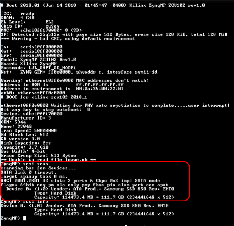
- Once the board boots into U-Boot, ensure that the SATA interface is configured properly by using the following command:
scsi scan
If the scsi scan command reports an attached hard disk, perform the remainder of the boot by using the following command:
run sataboot
Note: The next set of steps are optional, which show how SATA is enabled in Vivado and how Boot images can be created using SDK.
Vivado Hardware Definition
- SATA is enabled by default in Vivado 2018.1 Board files. Same holds true for the Default ZCU102 Board Template HDF used in Petalinux 2018.1 and SDK 2018.1.
- Download and install the Vivado design tools.
- Launch Vivado and create a new project using the ZCU102 Rev1.0 or RevD as the board template. If you do not see the ZCU102 listed in the available boards, double-check the installation steps above before proceeding
- Once the project is created, create a new Vivado Block Diagram.
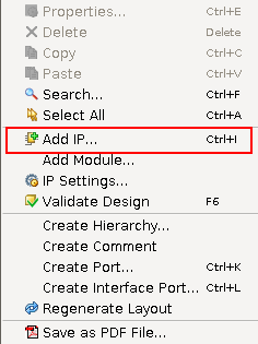
- In the Block Diagram, right-click and select "Add IP"
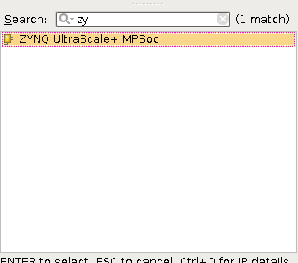
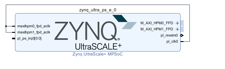
- In the search box that appears, type "Zynq" to filter to the "Zynq UltraScale+ MPSoC" IP. Press ENTER or double-click to select the IP and add it to the block diagram.
- Once the Zynq UltraScale+ MPSoC IP is added to the block diagram, click on the Run Block Automation option at the top of the block diagram to automatically configure the Zynq block based on the board-level options. Once the board automation is complete, manually route the clock signal from the pl_clk0 pin to the maxihpm0_fpd_aclk and maxihpm1_fpd_aclk pin.
- Double-click on the Zynq UltraScale+ MPSoC IP block to open the Re-customize IP GUI. Then, select I/O Configuration and expand the High Speed portion of the tree as shown. Note that SATA Lane 1 is enabled by default. Note that SATA Lane 1 on GT Lane 3 is the only valid configuration for SATA on the ZCU102.
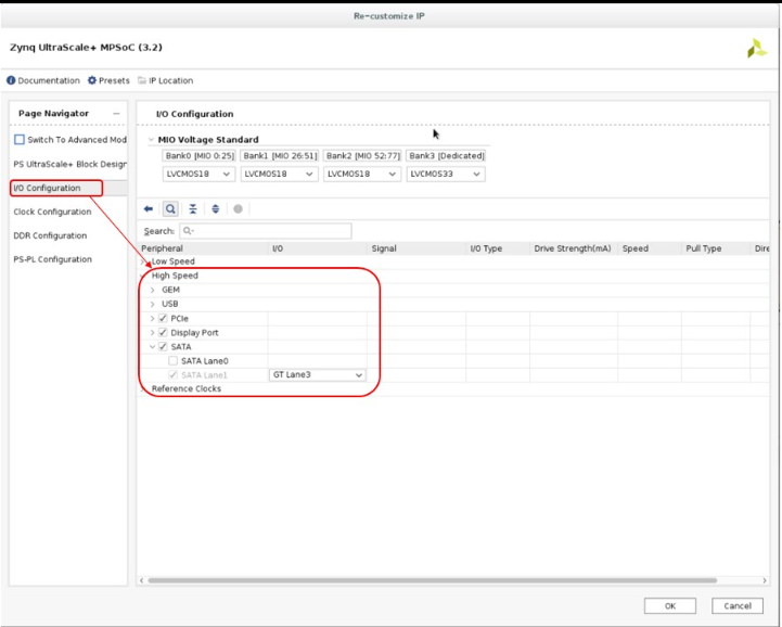
- When you are finished customizing the IP, click the OK button at the bottom of the GUI window.
- In the main Vivado cockpit, select the Source tab in the Sources pane. Then, right-click on the block diagram .bd file (named design_1.bd by default unless you selected a different name for you block diagram) and select Create HDL Wrapper... When prompted, use the option Let Vivado manage wrapper and auto-update.
- After the wrapper is created, click the option Run Implementation in the Flow Navigator pane on the Vivado cockpit. This process will take approximately 5 to 10 minutes to complete depending on the processing speed of your workstation.
- After the implementation process is complete, select the Open Implemented Design option.
- Next, select File-> Export-> Export Hardware to export the hardware design to a directory that you intend to use for the XSDK workspace. By default, this directory is inside the Vivado workspace but it can be located anywhere on disk. Since this design does not include a bitstream the Include Bitstream option can remain unchecked.
- Launch XSDK by using File-> Launch SDK. Be sure to select the appropriate directory locations for the "Exported location" and "Workspace" options.
First Stage Boot Loader (FSBL)
- Create a First Stage Boot Loader application project that targets either the APU CPU#0 or RPU CPU#0.
- Build the FSBL application by right-clicking on the application and selecting Clean Project followed by Build Project.
PMU Firmware
Create a PMU firmware application project in SDK. During creation of the application be sure to change the processor target to psu_pmu_0. Else, the PMU firmware application will not be available. No other modifications are required for PMU firmware.Device Tree Compiler
No changes are required for this step.Build the Device Tree Compiler exactly as described here - http://www.wiki.xilinx.com/Build+Device+Tree+Compiler+%28dtc%29
ARM Trusted Firmware
No changes are required for this step.Use ATf (bl31.elf) from PetALinux Project or Build ARM Trusted Firmware exactly as described here - http://www.wiki.xilinx.com/Build+ARM+Trusted+Firmware+%28ATF%29
Building the Final Boot Image
Create a .BIF file for use with the BootGen tool. This boot file will require the FSBL, PMU firmware, ARM Trusted Firmware, and U-Boot binaries. Below is an example BIF file://arch = zynqmp; split = false; format = BIN
the_ROM_image:
{
[fsbl_config]a53_x64
[bootloader]fsbl_a53.elf
[pmufw_image]pmufw.elf
[destination_cpu = a53-0, exception_level = el-3, trustzone]bl31.elf
[destination_cpu = a53-0, exception_level = el-2]u-boot.elf
}
© Copyright 2019 - 2022 Xilinx Inc. Privacy Policy