Zynq UltraScale+ MPSoC VCU TRD 2019.1 - PCIe Transcode
Zynq UltraScale+ MPSoC VCU TRD 2019.1 - PCIe Transcode
Table of Contents
1 Overview
The primary goal of this Design is to demonstrate the file based VCU transcode capabilities over PCIe present in Zynq UltraScale+ EV devices.
This design supports the following interfaces:
VCU Codec:
- Video Encode/Decode capability using VCU hard block in PL
- AVC/HEVC encoding.
- Encoder/decoder parameter configuration.
Communication Interface:
- PCIe
Video format:
- NV12
- NV16
Supported Resolution:
The table below provides the supported resolution from command line app only in this design.
| Resolution | Command Line |
| Single Stream | |
| 4kp60 | √ |
| 4kp30 | √ |
| 1080p60 | √ |
| 1080p30 | √ |
| 720p30 | √ |
√ - Supported
NA – Not applicable
x – Not supported
Hardware Overview
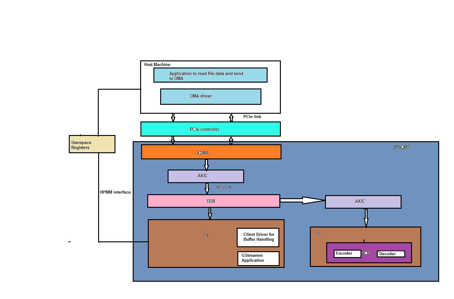
This Design uses the PCI Express (PCIe®) Endpoint block in an x4 Gen3 configuration along with DMA/Bridge Subsystem for PCI Express for data transfers between the host system memory and the Endpoint.
The DMA/Bridge Subsystem for PCI Express provides protocol conversion between PCIe transaction layer packets (TLPs) and AXI transactions. The hardware scatter-gather list (SGL) DMA interface is exercised to handle buffer management at the Endpoint to enable the memory mapped interface.
The downstream AXI4-Lite slaves include userspace registers, responsible for hand-shaking mechanism between host and the endpoint.
In the system to card direction, the DMA block moves data from the host memory to the PL-side through PCIe and then writes the data to PS-DDR via AXI-MM interface. Then VCU IP reads data from PS-DDR, performs Video encoding/decoding and writes it back to the same memory. Lastly, in card to system direction, DMA reads PS-DDR via AXI-MM interface and writes to host system memory through PCIe.

Figure 1: VCU PCIe Hardware Block Diagram
Components, Features, and Functions
4-lane integrated PCIe block with a maximum link speed of 8 GT/s (GT/s is Giga transfers per second)
- 128-bit at 250 MHz
DMA/Bridge subsystem for PCIe
- AXI Memory mapped enabled
- One of each DMA Read (H2C) & DMA write (C2H) channels
Apart from PCIe related IPs, the design contains VCU IP.
Software
The below figure shows the PCIe software block diagram
1.1 Board Setup
Refer below link for Board Setup
1.2 Run Flow
The TRD package is released with the source code, Vivado project, Petalinux BSP, host software required for PCIe and SD card image that enables the user to run the demonstration. It also includes the binaries necessary to configure and boot the ZCU106 board. Prior to running the steps mentioned in this wiki page, download the TRD package and extract its contents to a directory referred to as ‘TRD_HOME' which is the home directory.
Refer below link to download all TRD contents.
TRD package contents are placed in the following directory structure.
+rdf0428-zcu106-vcu-trd-2019-1
 +-- apu
 ¦   +-- apps
 ¦   +-- vcu_petalinux_bsp
 ¦   +-- vcu_sdx
 ¦   +-- ws_bypass
 +-- host_x86
 ¦   +-- host_package --> Ubuntu X86 Host dma driver and application
 +-- images
 ¦   +-- vcu_10g
 ¦   +-- vcu_audio
 ¦   +-- vcu_hdmirx
 ¦   +-- vcu_hdmitx
 ¦   +-- vcu_pcie  --> Pcie SD card images
 ¦   +-- vcu_plddr
 ¦   +-- vcu_sdirx
 ¦   +-- vcu_sdirxtx
 ¦   +-- vcu_sditx
 ¦   +-- vcu_sdx
 ¦   +-- vcu_trd
 +-- pl
 ¦   +-- constrs
 ¦   +-- pre-built
 ¦   +-- scripts
 ¦   +-- srcs
 +-- README.txt
The user needs to copy all the files from the $TRD_HOME/images/vcu_pcie/ to FAT32 formatted SD card directory.
Insert the board into the PCIe slot of the HOST machine and switch on board. Board bootup will take around 15-secs.
HOST PACKAGE
The PCIe HOST application(pcie_host_app) will read <input .mp4 file> file data from the HOST machine and send's it to zcu106 board which is connected to HOST machine PCIe slot as endpoint device. The data received from the HOST will be decoded and encoded using VCU hardware and writes the data to the HOST machine in .ts file format.
The files in host_package directory provides Xilinx PCIe DMA drivers, example software, to be used to exercise file transfer over the Xilinx PCIe DMA IP and perform the transcode use case using Xilinx VCU IP on zcu106 board.
Directory and file description:
===============================
- xdma/: This directory contains the Xilinx PCIe DMA kernel module driver files.
- libxdma/: This directory contains support files for the kernel driver module, which interfaces directly with the XDMA IP.
- include/: This directory contains all include files that are needed for compiling driver.
- etc/: This directory contains rules for the Xilinx PCIe DMA kernel module and software. The files in this directory should be copied to the /etc/directory on your Linux system.
- tools/: This directory contains example application software to exercise the provided kernel module driver and Xilinx PCIe DMA IP.
Copy the hosting package on to UBUNTU-14.04 machine and run the below commands to Install the XDMA driver and compile the host transcode application.
NOTE: Root permissions will be required to install xdma driver.
$ cd $TRD_HOME/host_x86/host_package

$ cd xdma

$ ./run_make.sh

$ cd ../tools

$ make
xdma0_control : to access XDMA registers
xdma0_xvc : to access userspace registers from HOST
xdma0_user : to access AXI-Lite Master interface
xdma0_bypass : to access DMA-Bypass interface
xdma0_h2c_0, xdma0_c2h_0: to access each channel
HOST APPLICATION
Run the below command to initiate a file transfer from the HOST machine and transcode it from the ZCU106 device. After running the application on HOST user need to start device application(pcie_transcode) on the zcu106 target to initiate the transfer.
$ ./pcie_host_app -i input file name -o output.ts ..
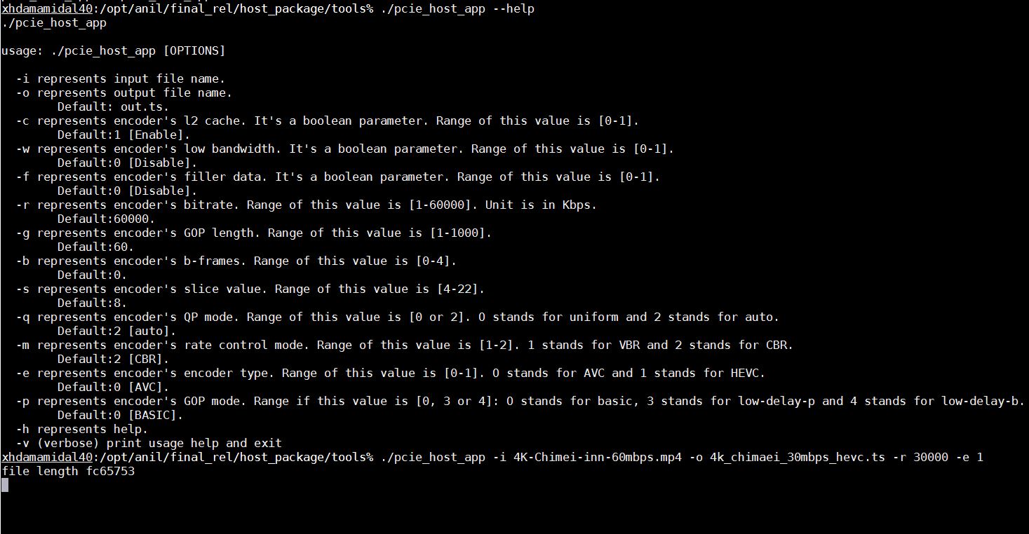
The user was given with the below options for transcoding the file :
usage: ./pcie_host_app [OPTIONS]

-i represents input file name.
-o represents output file name.
        Default: out.ts.
-c represents encoder's l2 cache. It's a boolean parameter. Range of this value is [0-1].
       Default:1 [Enable].
-w represents encoder's low bandwidth. It's a boolean parameter. Range of this value is [0-1].
      Default:0 [Disable].
-f represents encoder's filler data. It's a boolean parameter. Range of this value is [0-1].
      Default:0 [Disable].
-r represents encoder's bitrate. Range of this value is [1-60000]. Unit is in Kbps.
      Default:60000.
-g represents encoder's GOP length. Range of this value is [1-1000].
      Default:60.
-b represents encoder's b-frames. Range of this value is [0-4].
      Default:0.
-s represents encoder's slice value. Range of this value is [4-22].
      Default:8.
-q represents encoder's QP mode. Range of this value is [0 or 2]. O stands for uniform and 2 stands for auto.
     Default:2 [auto].
-m represents encoder's rate control mode. Range of this value is [1-2]. 1 stands for VBR and 2 stands for CBR.
      Default:2 [CBR].
-e represents encoder's encoder type. Range of this value is [0-1]. O stands for AVC and 1 stands for HEVC.
      Default:0 [AVC].
-p represents encoder's GOP mode. Range if this value is [0, 3 or 4]: O stands for basic, 3 stands for low-delay-p and 4 stands for low-delay-b.
       Default:0 [BASIC].
-h represents help.
-v (verbose) print usage help and exit
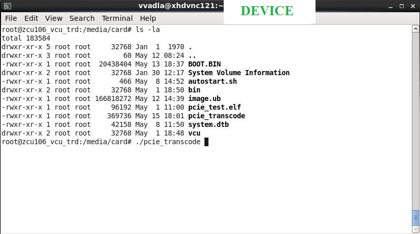
DEVICE APPLICATION
After booting the ZCU106 board with the SD images, to run the transcode use case first run the host side application mentioned as above and run the device application on the zcu106 device with the mentioned commands below. The host application will send file data to the device for transcoding it on the ZCU106 device and receives the transcoded data and saves it on to the host machine.
pcie_transcode
1.3 Build Flow
Refer below link for Build Flow
Zynq UltraScale+ MPSoC VCU TRD 2019.1 - Run and Build Flow
2 Other Information
2.1 Known Issues
- For VCU related known issues please refer AR# 72293: PetaLinux 2019.1 - Product Update Release Notes and Known Issues.
2.2 Limitations
- For playback in DP, video input resolution should match to DP's native resolution. This constraint is due to support of GUI. In GUI case if we allow video source other than native resolution(by setting fullscreen overlay) then graphics layer will disappear. To recover back GUI user need to kill and relaunch the GUI app. To avoid such condition TRD only supports video input resolution which is equal to DP's native resolution.
- For VCU related limitations please refer AR# 72293: PetaLinux 2019.1 - Product Update Release Notes and Known Issues and PG252 link.
2.3 Optimum VCU Encoder parameters for use-cases:
Quality: Low bitrate AVC encoding:
- Enable profile=high and use qp-mode=auto for low-bitrate encoding use-cases.
- The high profile enables 8x8 transform which results in better video quality at low bitrates.
© Copyright 2019 - 2022 Xilinx Inc. Privacy Policy