Cascade Interrupt Controller support in DTG
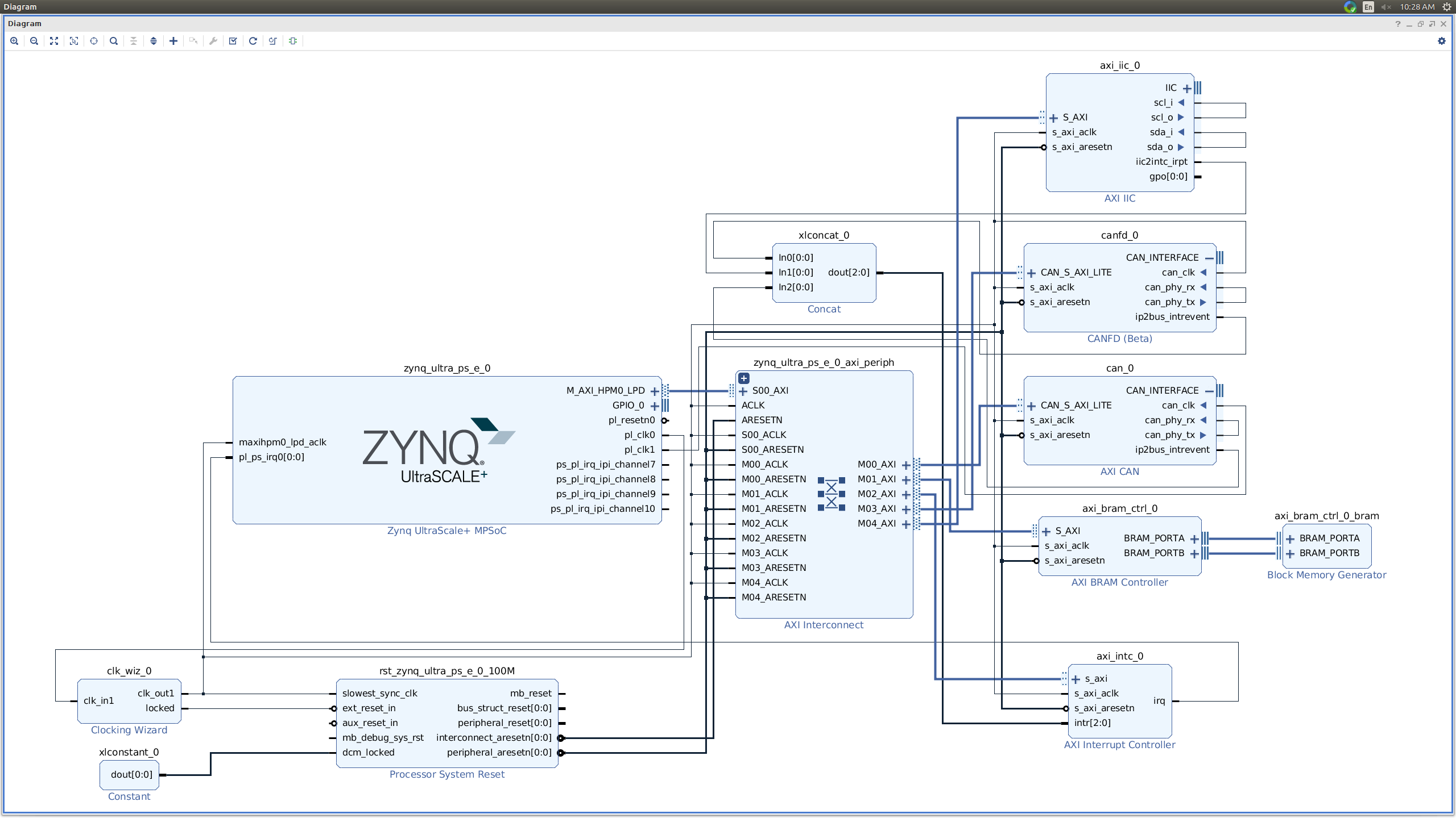
Here the PL peripherals used are axi_iic, can and canfd
All the interrupt pins of these are connected to axi_intc's intr pin
And the irq pin of axi_intc is connected to GIC(pl_ps_irq0)
Here the PL peripherals used are axi_iic, can, canfd, uart16550, uartlite_0 and two axi interrupt controllers.
The interrupt pins of axi_iic, can and canfd are connected to axi_intc_0 and
the interrupt pins of uart16550 and uartlite are connected to axi_intc_1.
The axi_intc_0 is cascaded to GIC(PL_PS_IRQ0) and axi_intc_1 is cascaded to GIC(PL_PS_IRQ1)
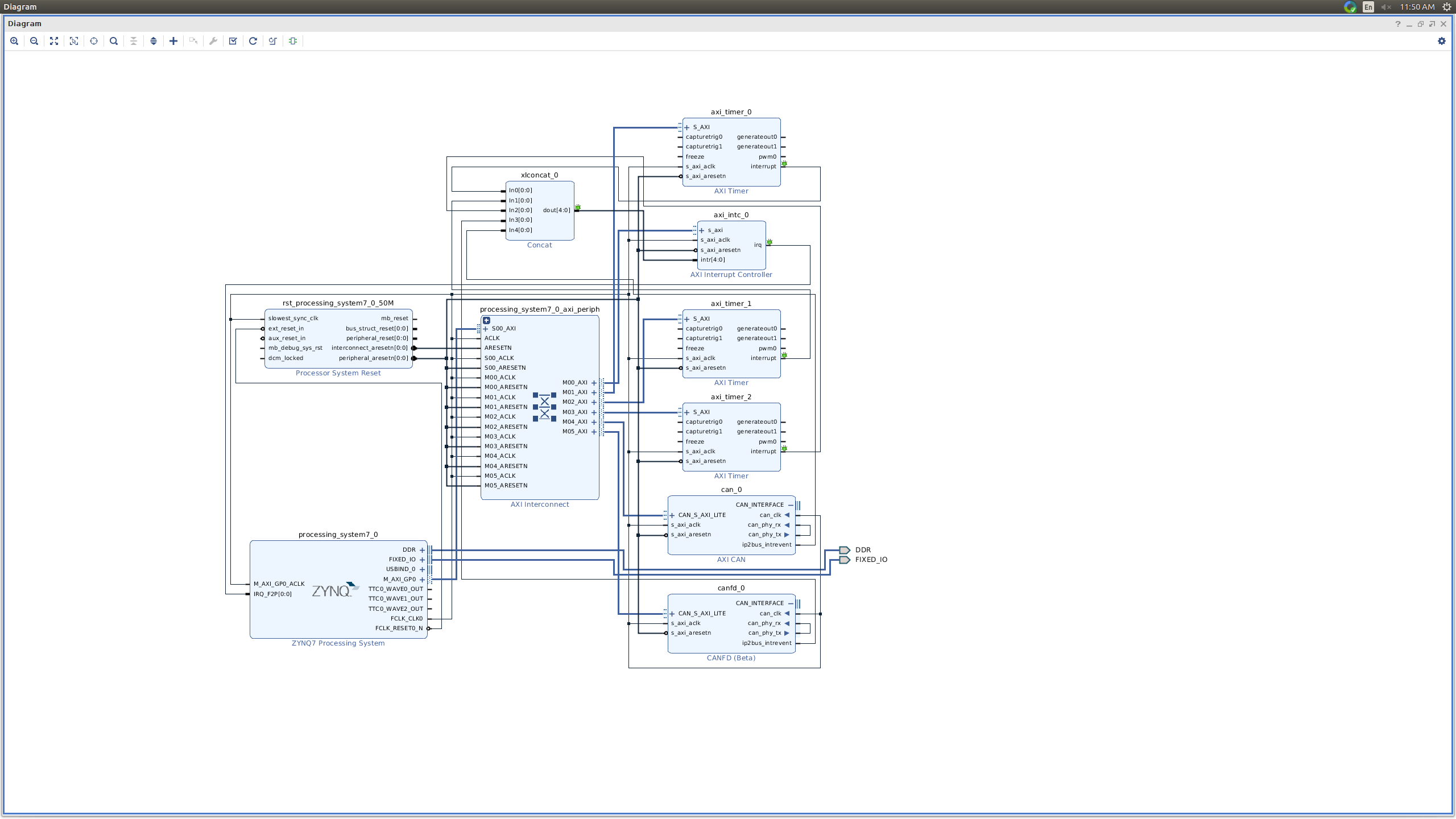
Here peripherals used are axi_timer, can and canfd
All the interrupt pins af timer, can and canfd are connected to axi_intc and the axi_intc cascaded to GIC(IRQ_F2P)
Test cases:
DTG should generate proper interrupts information as an example below
axi_gpio {
interrupt-parent = "axi_intc";
interrupt-id = <0 1>;
}
axi_interrupt-controller {
interrupt-parent = "gic"
interrupt-di = <0 89 1>;
}
Peripheral Registration
root@Xilinx-ZCU102:~# cat /proc/interrupts
50: 0 Xilinx INTC 1 Level -level 80030000.i2c
51: 1 Xilinx INTC 2 Level -level can1
52: 1 Xilinx INTC 0 Level -level can2
Please note, axi_iic at the time of probing will register its irq, so it can be shown directly in
cat /proc/interrupts.
but can and canfd can be shown in interrupts only, when the can devices are up, the above
log is taken when can and canfd are up, here Xilinx INTC is axi_intc
Description:
Axi interrupt controller can be connected in cascade mode on Zynq and ZynqMP platforms.
i.e. PL-interruptpin--->Axi-intc-→Gic
In this case, the peripherals using interrupt controller as Axi-Intc, will register their handlers to axi_intc and they can generate interrupts to axi-intc.
And Axi-Intc will register as perpheral to GIC and whenever peripheral generates interrupts to axi-intc, then it generates interrupts to gic.
ZynqMP With PL_PS_IRQ0 and Axi Intc
1) GIC(PL_PS_IRQ0)
Here the PL peripherals used are axi_iic, can and canfd
All the interrupt pins of these are connected to axi_intc's intr pin
And the irq pin of axi_intc is connected to GIC(pl_ps_irq0)
2) GIC(PL_PS_IRQ0 & PL_PS_IRQ1)
Here the PL peripherals used are axi_iic, can, canfd, uart16550, uartlite_0 and two axi interrupt controllers.
The interrupt pins of axi_iic, can and canfd are connected to axi_intc_0 and
the interrupt pins of uart16550 and uartlite are connected to axi_intc_1.
The axi_intc_0 is cascaded to GIC(PL_PS_IRQ0) and axi_intc_1 is cascaded to GIC(PL_PS_IRQ1)
Zynq
GIC(IRQ_F2P)
Here peripherals used are axi_timer, can and canfd
All the interrupt pins af timer, can and canfd are connected to axi_intc and the axi_intc cascaded to GIC(IRQ_F2P)
Test cases:
DTG should generate proper interrupts information as an example below
axi_gpio {
interrupt-parent = "axi_intc";
interrupt-id = <0 1>;
}
axi_interrupt-controller {
interrupt-parent = "gic"
interrupt-di = <0 89 1>;
}
- Case 1:
GIC(PL_PS_IRQ0)
- Here the PL peripherals used are axi_iic, can and canfd All the interrupt pins of these are connected to axi_intc's intr pin
And the irq pin of axi_intc is connected to GIC(pl_ps_irq0) - - Axi Intc Registration
/amba_pl@0/interrupt-controller@80010000: num_irq=3, edge=0x0/amba_pl@0/interrupt-controller@80010000: chained intc connected to irq 2
Peripheral Registration
root@Xilinx-ZCU102:~# cat /proc/interrupts
50: 0 Xilinx INTC 1 Level -level 80030000.i2c
51: 1 Xilinx INTC 2 Level -level can1
52: 1 Xilinx INTC 0 Level -level can2
Please note, axi_iic at the time of probing will register its irq, so it can be shown directly in
cat /proc/interrupts.
but can and canfd can be shown in interrupts only, when the can devices are up, the above
log is taken when can and canfd are up, here Xilinx INTC is axi_intc


