This page shows the following two examples:
IPI messaging example from PMU to RPU
IPI messaging example from RPU to PMU
...
The following example design is a demonstration on how to use Inter-Processor Interrupt (IPI) messaging interface between the PMU Firmware and APU/RPU/MicroBlaze processors located in the PS and the FPGA. The example helps users to understand how to add additional custom message capabilities to the PMU Firmware as well as to familiarize themselves with the different software drivers that can be used to take advantage of the IPI hardware.
Table of Contents
| Table of Contents |
|---|
...
|
...
...
|
Requirements
ZCU102 development board (This design example has been tested on silicon 4.0 rev1.0 board)
SDK (2018.1 release)
IPI messaging example from PMU to RPU
This design example shows how to send IPI messages from PMU to RPU periodically. PMU Firmware can be configured to send IPI message to RPU for every 10 seconds. RPU can be configured to receive IPI messages from PMU. In this example, PMU sends IPI messages to RPU and waits for response. RPU, after receiving an IPI message will respond back to PMU with success.
...
Start Xilinx SDK 2018.1
Go to File -> New -> Application Project
Give a project name (Ex: pmu_firmware)
Select Standalone in OS platform category. Select ZCU102_hw_platform(pre-defined) in Hardware Platform category. Select psu_pmu_0 in Processor category
Click Next. Select ZynqMP PMU Firmware from available templates and click on Finish to create project
Now download the zip file
View file name pmu_ipi_example_src.zip , extract and add the source files to PMU Firmware code base, define ENABLE_SCHEDULER and XPFW_DEBUG_DETAILED build flags and build the PMU Firmware
...
In SDK, go to File -> New -> Application Project
Give a project name (Ex: fsbl_r5)
Select psu_cortexr5_0 in Processor category
Click Next. Select Zynq MP FSBL from available templates and click on Finish to create project
...
In SDK, go to File -> New -> Application Project
Give a project name (Ex: ipi_example_app)
Select psu_cortexr5_0 in Processor category
Click Next. Select Empty Application from available templates and click on Finish to create project
Download these source files
View file name rpu_ipi_example_app_src.zip Extract the zip file. The src/ directory contains the required files for this example. Add these files to the project. Set EXAMPLE_IPI_RECEIVE macro to 0x1U and EXAMPLE_IPI_SEND macro to 0x0U in default.h file
...
In SDK, go to Xilinx -> Create Boot Image. Create Boot Image window appears as below
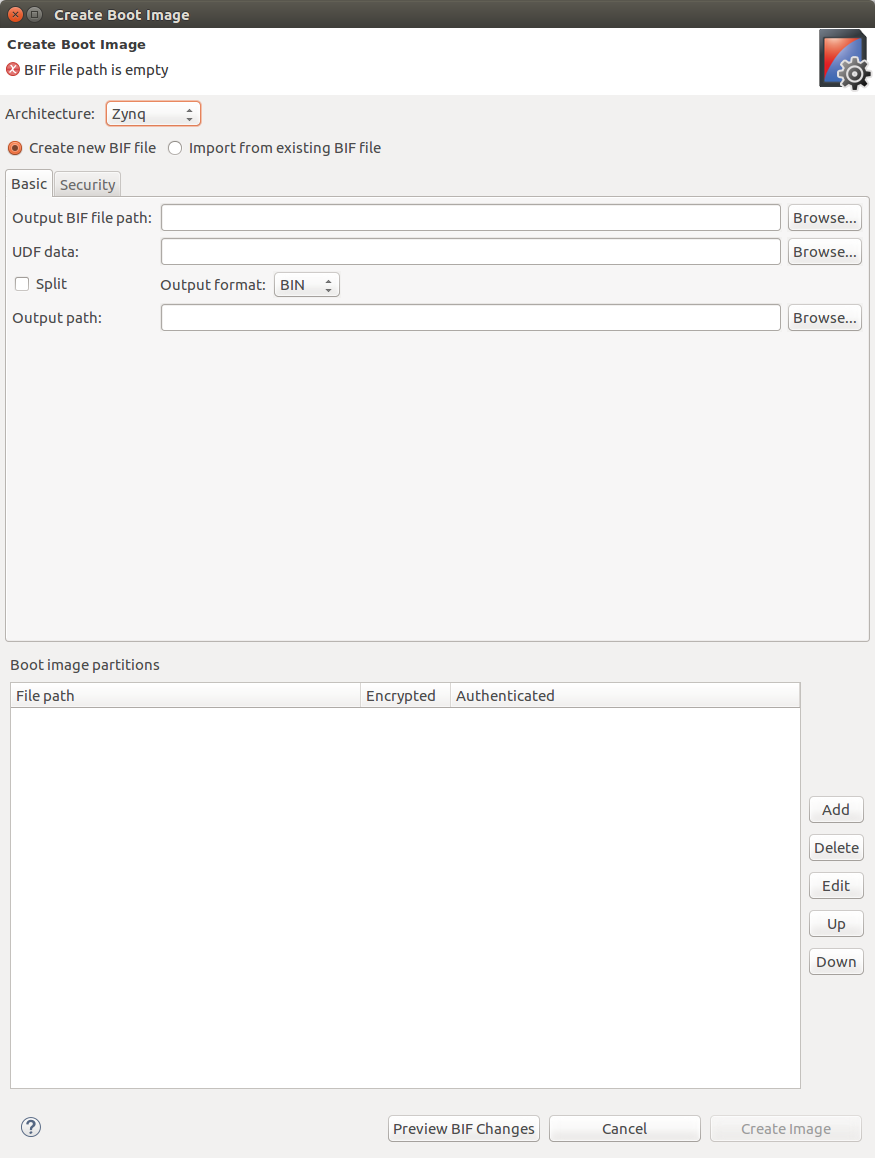
Select Zynq MP in Architecture category. Select Create new BIF file option
Browse and select path for Output BIF file path
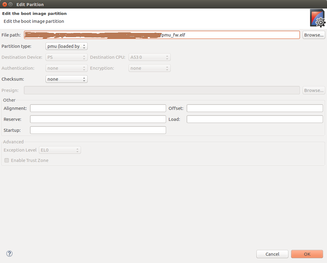
Click on Add to add partitions. Select pmu_firmware executable path at File path. Select Partition type as pmu (loaded by bootrom) and click OK. Here, we are using loading of PMU Firmware by BOOT ROM option. User can also select loading of PMU Firmware by FSBL. For that, select Partion type as datafile and Destination CPU as RPU 0.
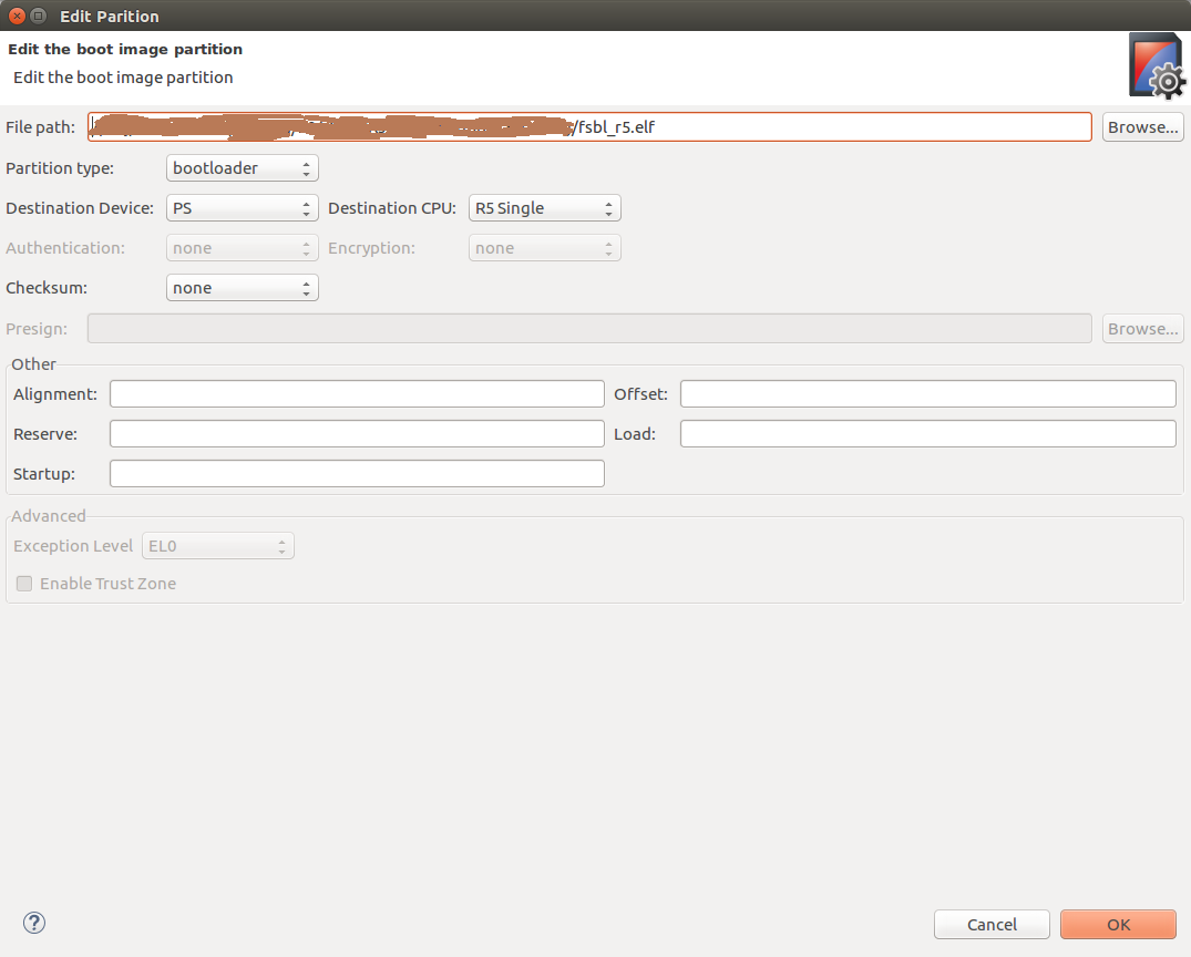
Click on Add button again to add FSBL partition. Select fsbl_r5 executable path at File path. Select Partition type as bootloader, Destination Device as PS and Destination CPU as R5 Single. Click OK. Please see the below image for reference
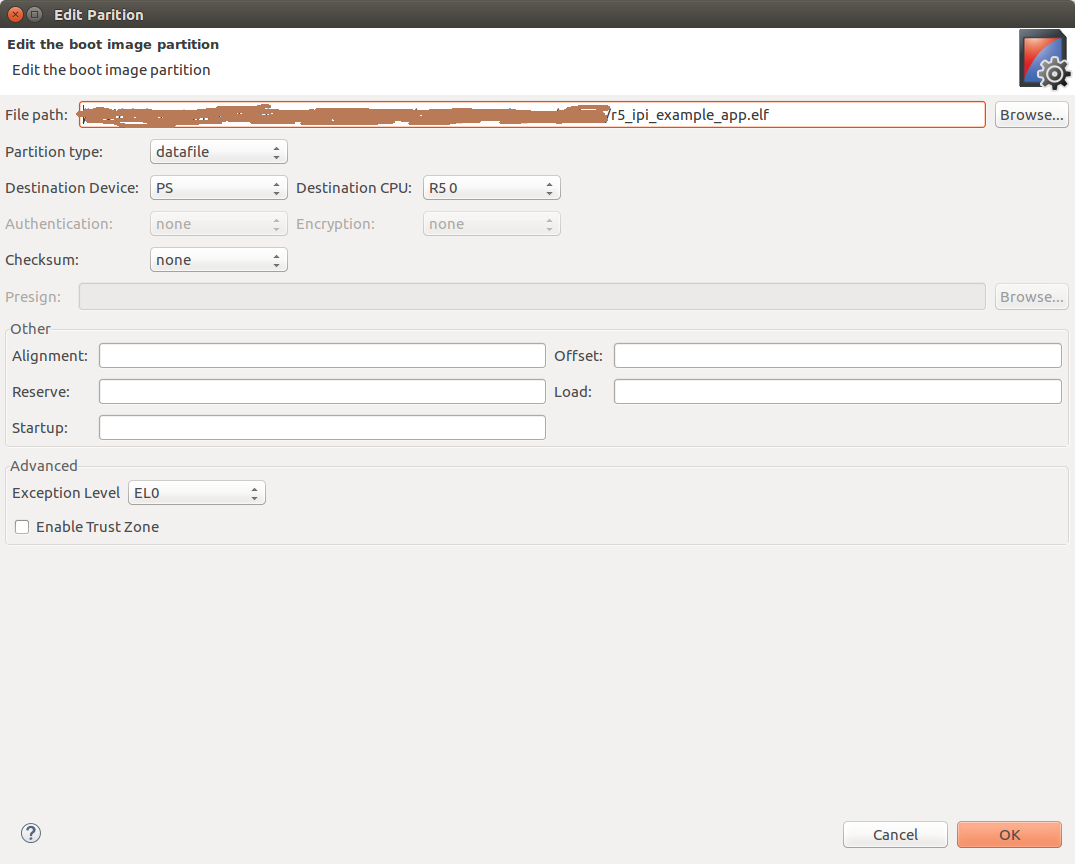
Again, click on Add button to select IPI example application partition. Select ipi_example executable path at File path. Select Partition type as datafile, Destination Device as PS and Destination CPU as R5 0. Click OK. Please see the below image for reference
Now click on Create Image. BOOT.BIN is created at Output BIF file path. Copy the BOOT.BIN to SD card and power-on ZCU102 board in SD boot mode. And observe prints on UART terminal
Snippet of BIF
Below is the snippet of BIF file created with the steps mentioned above
| Code Block |
|---|
//arch = zynqmp; split = false; format = BIN
the_ROM_image:
{
    [fsbl_config]r5_single
    [bootloader]C:\Images\fsbl_r5.elf
    [pmufw_image]C:\Images\pmu_fw.elf
    [destination_cpu = r5-0]C:\Images\r5_ipi_example_app.elf
}
|
Basic flow of execution
PMU Firmware application runs on PMU Microblaze. It registers a module which schedules a task for sending an IPI message to RPU and registers an IPI handler to be called whenever an IPI message is triggered to this module
R5 FSBL runs on R5 processor and hands-off to IPI Example application. RPU IPI example application initializes RPU GIC and connect IPI interrupt. It initializes IPI, enables IPI interrupt from PMU to RPU-0 and waits for IPI messages
PMU Firmware sends an IPI message with message number to RPU-0 periodically and waits for response from RPU
Whenever an IPI message is triggered from PMU, RPU gets an interrupt and the registered IPI interrupt handler is called
RPU reads the message, prints on terminal and sends success response to PMU. And the same repeates (steps 3 to 5)
IPI messaging example from RPU to PMU
This design example shows how to send IPI messages from RPU to PMU periodically. PMU Firmware can be configured to receive IPI messages from RPU. RPU can be configured to send IPI messages to PMU periodically (for every 10 seconds). In this example, RPU sends IPI messages to PMU and waits for response. PMU, after receiving an IPI message will respond back to RPU with success.
Create PMU Firmware application as mentioned in Create and modify PMU Firmware
Create RPU FSBL application as mentioned in Create FSBL application for RPU
Create RPU application for IPI Example as mentioned in Create RPU application for IPI Example. Set EXAMPLE_IPI_RECEIVE macro to 0x0U and EXAMPLE_IPI_SEND macro to 0x1U in default.h file
To create BOOT.BIN, follow the steps mentioned in Steps to create boot image
Basic flow
PMU Firmware application runs on PMU Microblaze. It registers a module which schedules a task for sending an IPI message to RPU and registers an IPI handler to be called whenever an IPI message is triggered to this module
R5 FSBL runs on R5 processor and hands-off to IPI Example application. RPU IPI example application initializes RPU GIC and connects TTC timer interrupt. It initializes timer to trigger an interrupt for every 10 seconds
Whenever RPU receives timer interrupt, the respective handler is being called which sends an IPI message to PMU and waits for response from PMU
When IPI is triggered from RPU, PMU receives an interrupt and the respective module's IPI handler is being called
PMU reads the message, prints on the terminal and sends success response to RPU. And the same repeats (steps 3 to 5)
Related Links
|
Introduction
The IPI hardware is used to communicate the different processors available in the Zynq UltraScale+ MPSoC device, though a series of buffers and interrupt signals. This is the mechanism used by the PMU Firmware to provide services to the APU or RPU processors using the XilPM library. In addition to these services, users might want to implement their own specific service in the PMU Firmware with communication capabilities.
The following example designs showcase how to modify the PMU Firmware code to add a custom module that makes use of the IPI communication layer, and how to implement a bare-metal application in the RPU and MicroBlaze processors as well as a Linux application in the APU that makes use of the IPI.
IPI (Inter-Processor Interrupt)
The IPI hardware is extensively described in a specific section within the Zynq UltraScale+ MPSoC TRM (UG1085). The implementation is based on multiple interrupt registers and message buffers and does not have any kind of specific protocol. The message buffers are limited to 32 bytes for a request and 32 bytes for response, so higher amounts of data can be exchanged using the buffers to provide pointers to other larger buffers.
As many of the other controllers in the device, the embedded software package provides specific drivers that can be used by the different processors. It is important to recall that the drivers are only available for the APU and the RPU, so processors implemented in the PL (i.e. MicroBlaze) cannot use the driver and need to implement their own driver instead.
Mailbox Library
The XilMailbox library provides the top-level hooks for sending or receiving an IPI message using the Zynq UltraScale+ MPSoC IPI hardware.
Libmetal
The libmetal library provides common user APIs to access devices, handle device interrupts, and request memory across different operating environments. In this case, the library provides communication APIs that can be used from Linux userspace without using any specific driver to access the hardware.
Application
The example application is used to demonstrate messaging between the PMU and the different processors available in the device. The control flow is simple as the PMU Firmware monitors incoming messages to detect when all the processors started executing. Once a message is received from each one of them, it starts sending messages periodically to them.
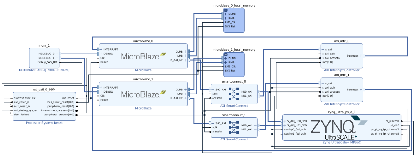
Hardware Block Design
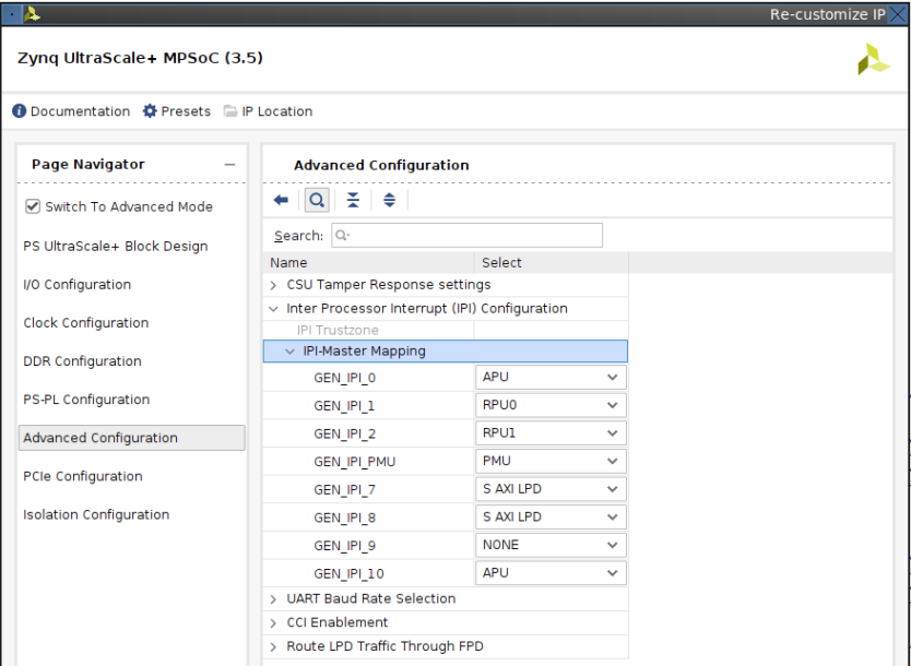
The hardware design required to implement this example design is fairly simple with two MicroBlaze processors with dedicated interrupt handlers that are connected to the IPI channel 7 and 8 signals. These interrupt signals are exposed to the PL side when the S_AXI_LPD is selected in the IPI-Master Mapping configuration shown in the bellow image. The MicroBlaze processors are also connected to the Processing Subsystem using the HP0/HP1 ports in order to be able to access the IPI address space.
The Processing Subsystem configuration is the default one for the ZCU102 board excluding the IPI configuration. The below image shows the channel assignment selected, which assigns two interrupts to the APU. The reason behind this configuration is the fact that the channel 0 is dedicated to the zynqmp-ipi-mailbox kernel driver, that is used by the zynqmp-firmware kernel driver.
Software
PMU Firmware
The PMU Firmware architecture is extensively described in the Zynq UltraScale+ MPSoC Software Developers Guide (UG1137). The two key elements for this example are the concept of PMU Firmware Modules and the Handling of IPI within the PMU Firmware.
Custom Module
As discussed in the PMU Firmware Usage section of UG1137, the PMU Firmware already provides a custom module initialization prototype that can be used to create a new module. Based on the code sample provided in the documentation, a custom IPI messaging module has been added to the source code defining a custom IPI ID and adding a scheduled task (XPFW_IPI_MSG_SEND_TIME period) to implement the example functionality.
| Code Block | ||
|---|---|---|
| ||
static void IpiModCfgInit(const XPfw_Module_t *ModPtr, const u32 *CfgData, u32 Len)
{
	XPfw_CoreScheduleTask(ModPtr, XPFW_IPI_MSG_SEND_TIME, XPfw_SendIpi);
}

void ModCustomInit(void)
{
	IpiModPtr = XPfw_CoreCreateMod();

	XPfw_CoreSetCfgHandler(IpiModPtr, IpiModCfgInit);
	XPfw_CoreSetIpiHandler(IpiModPtr, IpiHandler, XPFW_IPI_ID);
} |
IPI Handler
The IPI handler in the custom module is only triggered when the IPI manager layer receives a message with the associated module ID header (in this case XPFW_IPI_ID). For this example design, the handler is used to receive the initial message from the application processors, so the scheduled task starts sending messages to the processor that sent the message.
| Code Block | ||
|---|---|---|
| ||
static void IpiHandler(const XPfw_Module_t *ModPtr, u32 IpiNum, u32 SrcMask, const u32* Payload, u8 Len)
{
	for(u32 idx=0; idx < 4; idx++) {
		if((channel[idx].mask == SrcMask) && (channel[idx].init == 0)) {
			channel[idx].init = 1;
			XPfw_Printf(DEBUG_PRINT_ALWAYS,"PMUFW: IPI received from %s\r\n", channel[idx].name);
		}
	}
} |
Each channel is represented by a mask value and a string representing the channels name that is printed in the serial port for monitoring purposes.
| Code Block | ||
|---|---|---|
| ||
/* IPI Channels used in the example */
ipi_ch_t channel[] = {
                {IPI_PMU_0_IER_RPU_0_MASK, 0, "RPU0"},
                {IPI_PMU_0_IER_RPU_1_MASK, 0, "RPU1"},
                {1<<24, 0, "MB0"}, // MicroBlaze #0 assigned to PL0
                {1<<25, 0, "MB1"}, // MicroBlaze #1 assigned to PL1
                {1<<27, 0, "APU"}  // APU assigned to PL3
}; |
IPI Messaging Task
The IPI messaging in the custom module is performed through the specific API provided by the PMU Firmware core. The XPfw_IpiWriteMessage and XPfw_IpiReadResponse are used for sending the message and reading the reply, while XPfw_IpiTrigger and XPfw_IpiPollForAck are for control purposes. The task monitors whether all the channels have been initialized and if so will send a message to every channel, read the response and check if the counter value returned is equal to the one that has been send.
| Code Block | ||
|---|---|---|
| ||
static void XPfw_SendIpi(void)
{
        s32 Status;
        u32 MsgPtr[1] = {0};
        u32 RespPtr[1] = {0};

        /* Create message */
        MsgPtr[0] = cnt;  // Counter value

        /* Check if all the channels have been initialized */
        for(u32 idx = 0; idx < CHANNELS; idx++) {
                if(!channel[idx].init) {
                        return;
                }
        }

        /* Send IPI Message to each channel */
        for(u32 idx = 0; idx < CHANNELS; idx++) {

                XPfw_Printf(DEBUG_PRINT_ALWAYS, "PMUFW ModIPI: Send message number %d to %s\r\n", cnt, channel[idx].name);

                Status = XPfw_IpiWriteMessage(IpiModPtr, channel[idx].mask, MsgPtr, sizeof(MsgPtr)/sizeof(MsgPtr[1]));
                if(XST_SUCCESS != Status) {
                        XPfw_Printf(DEBUG_ERROR, "PMUFW ModIPI: IPI Write Message failed\r\n", idx);
                        break;
                }

                Status = XPfw_IpiTrigger(channel[idx].mask);
                if(XST_SUCCESS != Status) {
                        XPfw_Printf(DEBUG_ERROR, "PMUFW ModIPI: IPI %d Trigger failed\r\n", idx);
                        break;
                }

                Status = XPfw_IpiPollForAck(channel[idx].mask, 100);
                if(XST_SUCCESS != Status) {
                        XPfw_Printf(DEBUG_ERROR, "PMUFW ModIPI: IPI %d Poll for ACK Timeout\r\n", idx);
                        break;
                }

                Status = XPfw_IpiReadResponse(IpiModPtr, channel[idx].mask, RespPtr, sizeof(RespPtr)/sizeof(RespPtr[1]));
                if(XST_SUCCESS != Status) {
                        XPfw_Printf(DEBUG_ERROR, "PMUFW ModIPI: IPI %d Read Response failed\r\n", idx);
                        break;
                }

                if((RespPtr[0] & 0xFFFF) != cnt) {
                        XPfw_Printf(DEBUG_ERROR, "PMUFW ModIPI: IPI %d Response invalid\r\n", idx);
                        break;
                }

                XPfw_Printf(DEBUG_PRINT_ALWAYS, "PMUFW ModIPI: Received message number %d from %s\r\n", cnt, channel[idx].name);
        }

        cnt++;
}
|
R5#0 Application
The RPU0 application is based on the IPI driver, which is used to send the initial message to the PMU Firmware as well as to reply to messages incoming from the PMU. This driver provides fine granularity to generate the interrupts as well as to write messages or responses.
RPU to PMU message
The application starts sending an initial message to the PMU channel 0 with the custom module ID so it gets handled by the custom module discussed earlier in this page. There is no additional data added to the message as it is only used by the PMU Firmware to monitor active processors.
| Code Block | ||
|---|---|---|
| ||
/* Create message with the IPI module ID */
u32 TmpBufPtr[] = { XPFW_IPI_ID << 16 };

XIpiPsu_WriteMessage(&IpiInst, XPAR_XIPIPS_TARGET_PSU_PMU_0_CH0_MASK, TmpBufPtr, sizeof(TmpBufPtr) / sizeof(&TmpBufPtr), XIPIPSU_BUF_TYPE_MSG);
XIpiPsu_TriggerIpi(&IpiInst, XPAR_XIPIPS_TARGET_PSU_PMU_0_CH0_MASK);

do {
	/**
	 * Do Nothing
	 * We need to loop on to receive IPIs and respond to them
	 */
	__asm("wfi");
} while (1); |
PMU to RPU messages
Messages from the PMU are handled by the IPI interrupt handler registered in the application code. The interrupt handler makes use of the IPI driver’s API to read the incoming message and return the same value in the response buffer.
| Code Block | ||
|---|---|---|
| ||
void IpiIntrHandler(void *XIpiPsuPtr)
{
	u32 SrcIndex;
	XIpiPsu *InstancePtr = (XIpiPsu *) XIpiPsuPtr;

	u32 TmpBufPtr[] = { 0 };
	u32 IpiSrcMask = XIpiPsu_GetInterruptStatus(InstancePtr);

	/* Poll for each source */
	for (SrcIndex = 0U; SrcIndex < InstancePtr->Config.TargetCount;	SrcIndex++) {

		if (IpiSrcMask & InstancePtr->Config.TargetList[SrcIndex].Mask) {

			/*  Read Incoming Message Buffer Corresponding to Source CPU */
			XIpiPsu_ReadMessage(InstancePtr,
					InstancePtr->Config.TargetList[SrcIndex].Mask, TmpBufPtr,
					sizeof(TmpBufPtr) / sizeof(*TmpBufPtr), XIPIPSU_BUF_TYPE_MSG);

			/* Send Response */
			XIpiPsu_WriteMessage(InstancePtr,
					InstancePtr->Config.TargetList[SrcIndex].Mask, TmpBufPtr,
					sizeof(TmpBufPtr) / sizeof(*TmpBufPtr), XIPIPSU_BUF_TYPE_RESP);

			/* Clear the Interrupt Status - This clears the OBS bit on teh SRC CPU registers */
			XIpiPsu_ClearInterruptStatus(InstancePtr,
					InstancePtr->Config.TargetList[SrcIndex].Mask);
		}
	}
} |
R5#1 Application
The RPU1 application is based on the mailbox library, which is used to send the initial message to the PMU Firmware as well as to reply to messages incoming from the PMU. This library abstracts the IPI driver API for a more intuitive approach but lacks fine granularity to generate the interrupts. For example, the mailbox library generates the interrupt signal to the target processor when writing in the response buffer using the XMailbox_SendData function. Additionally, the mailbox driver checks whether the GIC Distributor is already initialized and skips the interrupt exception configuration step. This implementation is not suitable for a multicore cluster as the second processor running the XIpiPs_RegisterIrq function will skip the configuration of the exception. Therefore initializing the GIC and enabling the exceptions is a required step in the application code.
| Code Block | ||
|---|---|---|
| ||
/* Initialize the interrupt controller driver */
XScuGic_Config *IntcConfig = XScuGic_LookupConfig(XPAR_SCUGIC_0_DEVICE_ID);
XScuGic_CfgInitialize(&GicInst, IntcConfig, IntcConfig->CpuBaseAddress);

Xil_ExceptionRegisterHandler(XIL_EXCEPTION_ID_INT,(Xil_ExceptionHandler) XScuGic_InterruptHandler, &GicInst);
Xil_ExceptionEnable(); |
RPU to PMU message
The Application starts sending an initial message to the PMU channel 0 with the custom module ID using the XilMailbox API such that an interrupt is generated automatically in the target. There is no additional data added to the message as it is only used by the PMU Firmware to monitor active processors.
| Code Block | ||
|---|---|---|
| ||
/* Create message with the IPI module ID */
u32 TmpBufPtr[] = { XPFW_IPI_ID << 16 };

XMailbox_SendData(&XMboxInstance, XPAR_XIPIPS_TARGET_PSU_PMU_0_CH0_MASK, TmpBufPtr, sizeof(TmpBufPtr) / sizeof(*TmpBufPtr), XILMBOX_MSG_TYPE_REQ, 1);

do {
	/**
	 * Do Nothing
	 * We need to loop on to receive IPIs and respond to them
	 */
	__asm("wfi");
} while (1); |
PMU to RPU messages
The Mailbox interrupt handler is responsible for taking care of incoming messages through the IPI interface. In this case, using both the receive and send API calls the message is loopback to the PMU without any change.
| Code Block | ||
|---|---|---|
| ||
static void MailboxHandler(void *CallBackRef)
{
	u32 Status = XST_FAILURE;
	u32 TmpBufPtr[] = { 0 };

	Status = XMailbox_Recv(&XMboxInstance, XPAR_XIPIPS_TARGET_PSU_PMU_0_CH0_MASK, TmpBufPtr, sizeof(TmpBufPtr) / sizeof(*TmpBufPtr), XILMBOX_MSG_TYPE_REQ);
	if (Status != XST_SUCCESS) {
		xil_printf("Reading an IPI Resp message Failed\n\r");
		return;
	}

	Status = XMailbox_SendData(&XMboxInstance, XPAR_XIPIPS_TARGET_PSU_PMU_0_CH0_MASK, TmpBufPtr, sizeof(TmpBufPtr) / sizeof(*TmpBufPtr), XILMBOX_MSG_TYPE_RESP, 0);
	if (Status != XST_SUCCESS) {
		xil_printf("Sending Req Message Failed\n\r");
		return;
	}
} |
MicroBlaze #0 and #1 Applications
The MicroBlaze application does not have access to the IPI driver in its domain BSP code, therefore individual register access is required to handle the communication channel.
MicroBlaze #0:
| Code Block |
|---|
#define IPI_PMUTOMB_REQ_BUFF 0xff990EC0
#define IPI_PMUTOMB_RES_BUFF 0xff990EE0
#define IPI_MBTOPMU_REQ_BUFF 0xFF9907C0

#define IPI_MB_TRIG	0xff340000
#define IPI_MB_ISR 0xff340010
#define IPI_MB_IER 0xff340018 |
MicroBlaze #1:
| Code Block |
|---|
#define IPI_PMUTOMB_REQ_BUFF 0xff990F00
#define IPI_PMUTOMB_RES_BUFF 0xff990F20
#define IPI_MBTOPMU_REQ_BUFF 0xFF9909C0

#define IPI_MB_TRIG	0xff350000
#define IPI_MB_ISR 0xff350010
#define IPI_MB_IER 0xff350018 |
MB to PMU
The application makes use of register access functions to write the initial message and to trigger the IPI interrupt signal.
| Code Block | ||
|---|---|---|
| ||
/* Write message with the IPI module ID */
Xil_Out32(IPI_MBTOPMU_REQ_BUFF, (XPFW_IPI_ID << 16));
Xil_Out32(IPI_MB_TRIG, XPAR_XIPIPS_TARGET_PSU_PMU_0_CH0_MASK); |
PMU to MB
Similar to the code used by the RPU#0 processor with the IPI driver API, the interrupt handler is just a simple buffer loopback implementation, finishing with a register access that clears the interrupt signal, and generating an acknowledgment in the PMU clearing the OBS bit.
| Code Block | ||
|---|---|---|
| ||
u32 TmpBufPtr[] = { 0 }; /**< Holds the received Message, later inverted and sent back as response*/
u32 *SrcBufferPtr = (u32*)IPI_PMUTOMB_REQ_BUFF;
u32 *DstBufferPtr = (u32*)IPI_PMUTOMB_RES_BUFF;
u32 Index;

/* Copy the IPI Buffer contents into Users's Buffer*/
for (Index = 0U; Index < (sizeof(TmpBufPtr)/sizeof(TmpBufPtr*)); Index++) {
	TmpBufPtr[Index] = SrcBufferPtr[Index];
}

/* Copy the Message to IPI Buffer */
for (Index = 0U; Index < (sizeof(TmpBufPtr)/sizeof(TmpBufPtr*)); Index++) {
	DstBufferPtr[Index] = TmpBufPtr[Index];
}

/* Clear the Interrupt Status - This clears the OBS bit on the SRC CPU registers */
Xil_Out32(IPI_MB_ISR, ~0); |
Linux
The Linux application cannot access directly to the IPI register space as userspace applications do not have direct access to physical memory/addresses. Instead, the application will make use of libmetal library to have access to the required IPI address space, and in this way implement the message handling in top of it. As documented in the Libmetal and OpenAMP User Guide, the libmetal implementation for Linux is based on the UIO kernel driver, which will define the available address space.
Application
The Linux application is quite similar to the MicroBlaze processor based application in that libmetal is only used to have read/write access to the IPI address space. There is no other driver that implements the IPI functionality and therefore both message writing or interrupt triggering operations are performed with individual write functions. The main difference is the need to initialize the libmetal devices and memory regions as well as the interrupt handler.
| Code Block | ||
|---|---|---|
| ||
static int ipi_irq_handler (int vect_id, void *priv)
{
        uint32_t TmpBufPtr[] = { 0 }; /**< Holds the received Message, later inverted and sent back as response*/
        uint32_t Index;

        /* Copy the IPI Buffer contents into Users's Buffer*/
        for (Index = 0U; Index < (sizeof(TmpBufPtr)/sizeof(*TmpBufPtr)); Index++) {
                TmpBufPtr[Index] = metal_io_read32(ipi_io_buffer, IPI_PMUTOCH10_REQ_OFFSET + (sizeof(*TmpBufPtr) * Index));
        }

        /* Copy the Message to IPI Buffer */
        for (Index = 0U; Index < (sizeof(TmpBufPtr)/sizeof(*TmpBufPtr)); Index++) {
                metal_io_write32(ipi_io_buffer, IPI_PMUTOCH10_RES_OFFSET + (sizeof(*TmpBufPtr) * Index), TmpBufPtr[Index]);
        }

        /* Clear the Interrupt Status - This clears the OBS bit on the SRC CPU registers */
        metal_io_write32(ipi_io, IPI_ISR_OFFSET, ~0);

        return METAL_IRQ_HANDLED;
}


int main(void)
{
        int ret;
        struct metal_init_params init_param = METAL_INIT_DEFAULTS;

        ret = metal_init(&init_param);
        if (ret) {
                printf("Failed to initialize Metal\n");
                goto err1;
        }

        metal_set_log_level(METAL_LOG_NOTICE);

        /* Open and map IPI buffer memory region */
        ret = metal_device_open(BUS_NAME, IPI_BUF_DEV_NAME, &ipi_buf_dev);
        if (ret) {
                printf("Failed to open device %s\n", IPI_BUF_DEV_NAME);
                goto err2;
        }

        ipi_io_buffer = metal_device_io_region(ipi_buf_dev, 0);
        if (!ipi_io_buffer) {
                printf("Failed to map io buffer region for %s\n", ipi_buf_dev->name);
                ret = -ENODEV;
                goto err3;
        }

        /* Open and map IPI interrupt memory region */
        ret = metal_device_open(BUS_NAME, IPI_DEV_NAME, &ipi_dev);
        if (ret) {
                printf("Failed to open device %s\n", IPI_DEV_NAME);
                goto err3;
        }

        ipi_io = metal_device_io_region(ipi_dev, 0);
        if (!ipi_io) {
                printf("Failed to map io region for %s\n", ipi_dev->name);
                ret = -ENODEV;
                goto err4;
        }

        /* Register interrupt handler */
        ipi_irq = (intptr_t)ipi_dev->irq_info;
        metal_irq_register(ipi_irq, ipi_irq_handler, 0);
        metal_irq_enable(ipi_irq);

        /* Enable Remote IPIs */
        metal_io_write32(ipi_io, IPI_IER_OFFSET, REMOTE_IPI_MASK);

        /* Write message with the IPI module ID */
        metal_io_write32(ipi_io_buffer, IPI_CH10TOPMU_REQ_OFFSET, (XPFW_IPI_ID << 16));
        metal_io_write32(ipi_io, IPI_TRIG_OFFSET, IPI_PMU_MASK);

        while(1);

        metal_io_write32(ipi_io, IPI_IDR_OFFSET, REMOTE_IPI_MASK);
        metal_irq_disable(ipi_irq);
        metal_irq_unregister(ipi_irq);

err4:
        metal_device_close(ipi_dev);
err3:
        metal_device_close(ipi_buf_dev);
err2:
        metal_finish();
err1:
        return ret;
} |
Device-Tree
As mentioned previously, the libmetal library is built in top of the UIO kernel driver, which requires device-tree nodes to describe the address space available for the driver. Additionally, the UIO driver requires the usage of the kernel’s command line parameters to define the UIO driver’s id name using the uio_pdrv_genirq.of_id parameter.
The following system-user.dtsi file can be used in PetaLinux based Linux image:
| Code Block | ||
|---|---|---|
| ||
/include/ "system-conf.dtsi"
/ {
  chosen {
    bootargs = "earlycon console=ttyPS0,115200 clk_ignore_unused root=/dev/ram0 rw init_fatal_sh=1 uio_pdrv_genirq.of_id=uio";
  };

  /* IPI Interrupt register */
  ipi@ff370000 {
    compatible = "uio";
    reg = <0x0 0xff370000 0x0 0x10000>;
    interrupt-parent = <&gic>;
    interrupts = <0 32 4>;
  };

  /* IPI Message buffer */
  ipi_buf@ff990000 {
    compatible = "uio";
    reg = <0x0 0xff990000 0x0 0x1000>;
  };
}; |
Example Source Files
This example design has been tested using a ZCU102 board and the Vivado/Vitis/PetaLinux 2023.1 release.
It can be easily reproduced using the following files in the github repository:
zcu102_ipi_bd.tcl to regenerate the BD design in a Vivado project targeting the ZCU102 board
main_r5_0.c, main_r5_1.c, main_mb0.c and main_mb1.c as baremetal application code targeting the different processors in the system
xpfw_mod_custom.c as custom PMU Firmware module code
testapp.c as Linux application
Example Results
| Code Block |
|---|
Zynq MP First Stage Boot Loader
Release 2023.1   May  1 2023  -  00:38:12
PMUFW: IPI received from MB0
PMUFW: IPI received from MB1
PMUFW: IPI received from RPU0
PMUFW: IPI received from RPU1


U-Boot 2023.01 (Mar 29 2023 - 13:08:40 +0000)

<U-Boot log>

Starting kernel ...

[    0.000000] Booting Linux on physical CPU 0x0000000000 [0x410fd034]
[    0.000000] Linux version 6.1.5-xilinx-v2023.1 (oe-user@oe-host) (aarch64-xilinx-linux-gcc (GCC) 12.2.0, GNU ld (GNU Binutils) 2.39.0.20220819) #1 SMP Fri Apr 21 07:47:58 UTC 2023
[    0.000000] Machine model: ZynqMP ZCU102 Rev1.0

<Linux boot log>

/ # testapp
PMUFW: IPI received from APU
PMUFW ModIPI: Send message number 0 to RPU0
PMUFW ModIPI: Received message number 0 from RPU0
PMUFW ModIPI: Send message number 0 to RPU1
PMUFW ModIPI: Received message number 0 from RPU1
PMUFW ModIPI: Send message number 0 to MB0
PMUFW ModIPI: Received message number 0 from MB0
PMUFW ModIPI: Send message number 0 to MB1
PMUFW ModIPI: Received message number 0 from MB1
PMUFW ModIPI: Send message number 0 to APU
PMUFW ModIPI: Received message number 0 from APU
PMUFW ModIPI: Send message number 1 to RPU0
PMUFW ModIPI: Received message number 1 from RPU0
PMUFW ModIPI: Send message number 1 to RPU1
PMUFW ModIPI: Received message number 1 from RPU1
PMUFW ModIPI: Send message number 1 to MB0
PMUFW ModIPI: Received message number 1 from MB0
PMUFW ModIPI: Send message number 1 to MB1
PMUFW ModIPI: Received message number 1 from MB1
PMUFW ModIPI: Send message number 1 to APU
PMUFW ModIPI: Received message number 1 from APU |