| Table of Contents |
|---|
Introduction
...
Flow:

HW IP Features
- Full Bitstream and Partial Bitstream loading
- Encrypted and Authenticated Full/Partial Bitstream loading
- Readback of Configuration Registers
- Readback of Bitstream(Configuration Data)
- Compressed Bitstream
Features supported in the driver
- Full Bitstream Support
- Non Secure Bitstream
- Encrypted Bitstream
- Authenticated Bitstream
- Authenticated and Encrypted Bitstream
- Compressed Bitstream
- Loading Bitstream using Devicetree overlay
- Partial Bitstream Support that doesn't require PL drivers
- Non Secure Partial Bitstream
- Encrypted Partial Bitstream
- Authenticated Partial Bitstream
- Authenticated and Encrypted Partial Bitstream
- Readback
- Configuration Registers Readback
- Configuration Data Readback
Known Issues for PL Programing
The Xilinx device tree generator (https://github.com/Xilinx/device-tree-xlnx) currently lacks automated support for device tree overlay generation for Partial Reconfiguration / DFX designs. For systems requiring runtime device tree overlay (eg, Linux device driver support) support, hand-crafted device trees can be deployed and loaded. See the "Working with Device Tree Overlay (DTBO)" section below for details on how to load these at runtime.
Occasionally, bare-metal applications relying on the XilFPGA library may produce an error getting the DONE status. See Answer Record 70504 for more details - https://www.xilinx.com/support/answers/70504.html
Summary Table for Partial Reconfiguration / Dynamic Function Exchange Feature Support
Partial Reconfiguration / Dynamic Function Exchange (DFX) is an advanced feature of Xilinx Zynq UltraScale+ MPSoC devices. Refer to the table below for details. For PetaLinux releases prior to 2018.3 or for building Linux system images manually, please refer to the Linux OSL Flow page.
...
Kernel Configuration
The following config options has to be enabled in order to use FPGA Manager, Please note that these options are enabled by default through xilinx_zynqmp_defconfig except for the fpga debugfs option. If user wants to test readback feature they have enable it.
Zynq UltraScale+ MPSoC FPGA Manager Configuration:
Select: Device Drivers → FPGA Configuration Framework → Xilinx Zynq UltraScale+ MPSoC FPGA
In-order to test readback feature user needs to enable FPGA debug fs
Select: Device Drivers → FPGA Configuration Framework --> FPGA debug fs
...
CONFIG_CMASelect: Kernel Features --> Contiguous Memory Allocator
CONFIG_DMA_CMASelect: Device Drivers --> Generic Driver Options → DMA Contiguous Memory Allocator
Devicetree
| Code Block | ||
|---|---|---|
| ||
pcap {
       compatible = "xlnx,zynqmp-pcap-fpga";
       clocks = <&clk 41>;
};

fpga_full: fpga-full {
       compatible = "fpga-region";
       fpga-mgr = <&pcap>;
       #address-cells = <2>;
       #size-cells = <2>;
	   power-domains = <&zynqmp_firmware PL_PD>;
}; |
For more details about devicetree bindings Reference Below link: Devicetree
Note:
- Above devicetree node is by default present in the zynqmp.dtsi file
- power-domains: Property is optional. If this property is present it controls the PM domain specifier as defined by bindings of the power controller specified by phandle.
The PL_PD power domain will be turned on before loading the bitstream and turned off while removing/unloading the bitstream using overlays.
Bitstream Format
From 2018.3 release onwards FPGA Manager supports loading of vivado and bootgen generated Bitstream and Bin files vivadobootgen[1]
Note: For releases earlier to 2018.3 FPGA Manager was capable of loading only bootgen generated bin files. bootgen
.Bit Format
- Generated by Vivado
.Bin Format
- Generated by Vivado
- Generated by Bootgen by converting vivado generated bit file
Bootgen Command to generate bin file:
# bootgen -image Bitstream.bif -arch zynqmp -o ./Bitstream.bin -w (2018.1 or later releases)
# bootgen -image Bitstream.bif -arch zynqmp -process_Bitstream bin (2017.4 and earlier releases)
Bitstream.bif file should contains the below lines:
| Code Block | ||
|---|---|---|
| ||
all:
{
        [destination_device = pl] Full.bit (or)  Partial.bit /* Bitstream file name */
} |
Building Software Images
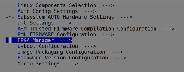
Xilinx tools (Petalinux, Yocto) provide an option with the name FPGA Manager which if enabled builds the device tree overlay fragments automatically and copies the Bitstream and DTBO files into root file system.
PetaLinux Flow
PetaLinux setup and build: PetaLinux
- Enable FPGA Manager in the top level PetaLinux menuconfig options.
| Code Block | ||
|---|---|---|
| ||
$ petalinux-config ---> FPGA Manager |
(OR)
Edit <plnx-proj-root>/project-spec/meta-user/conf/petalinuxbsp.conf file and add FPGA Manager package to EXTRA_IMAGE_FEATURES variable.
| Code Block | ||
|---|---|---|
| ||
EXTRA_IMAGE_FEATURES += " fpga-manager" |
2. Select FPGA Manager user

3. Select the Specify hw directory path, in the prompt provide HDF path

Note:
- By default it will pack base hdf Bitstream and dtbo to the /lib/firmware/base in the rootfs
- Specified hw directory path can contain multiple HDF's
4. Use petalinux-build command to build the required images
| Code Block | ||
|---|---|---|
| ||
$ petalinux-build |
Once build is complete, binaries are available at images/linux directory
5. Boot the hardware with newly built images
- Directory /lib/firmware in the rootfs contains the Bitstreams and dtbo files
Yocto Flow
Yocto setup and build: yocto
Once Yocto environment is set
- Edit <yocto-proj-root>/build/conf/local.conf add below lines of code
| Code Block | ||
|---|---|---|
| ||
EXTRA_IMAGE_FEATURES += " fpga-manager"
EXTRA_HDF = "<PATH_TO_HDF_or_XSA>" |
Note:
- By default it will pack base hdf Bitstream and dtbo to the /lib/firmware/base in the rootfs
- Extra hdf path can contain multiple HDF's
2. Build the required images (run below command)
| Code Block | ||
|---|---|---|
| ||
$ bitbake petalinux-image-minimal |
Once build is complete, binaries are available at ${DEPLOY_DIR_IMAGE} (${TMPDIR}/deploy/images/${MACHINE}/) directory
3. Boot the hardware with newly built images
- Directory /lib/firmware in the rootfs contains the Bitstreams and dtbo files
OSL Flow
Setup and Build: OSL
Images required for testing the FPGA Manager
- Bin/Bit file
- DTBO file
DTBO File Generation:
- Steps to Create the DT-Overlay Fragment
- Clone the device-tree-xlnx repo:
git clone device-tree-xlnx.git - Helper script: dt_overlay.tcl
- Command: # xsct dt_overaly.tcl system.hdf psu_cortexa53_0 device-tree-xlnx output_dir
- Clone the device-tree-xlnx repo:
Ex: xsct dt_overaly.tcl system.hdf psu_cortexa53_0 ${DTS_REPO}/device-tree-xlnx overlay
2. Create Device Tree Overlay Blob (.dtbo) file from the pl.dtsi file
# dtc -O dtb -o pl.dtbo -b 0 -@ pl.dtsi
Ex: ./scripts/dtc/dtc -O dtb -o pl.dtbo -b 0 -@ pl.dtsi
3. Copy the generated bit and dtbo files to target
Note: PL nodes should not be the part of Base Device-tree (system.dtb).
- If the PL nodes are part of static dtb (system.dtb), these nodes cannot be removed at run-time.
FPGA programming
- Linux FPGA Manager framework provides sysfs (Bitstream loading), debugfs (readback), configfs (Bitstream loading along with DTBO for PL drivers) attributes.
- Alternatively users can opt for Xilinx developed fpgautil. This utility provides an easy to use interface for programmers for all FPGA Manager use cases.
Exercising FPGA programming using fpgautil
Source code for the fpgautil is available here fpgautil.c
...
| theme | Midnight |
|---|
...
| Table of Contents |
|---|
Introduction
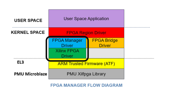
The Zynq UltraScale+ MPSoC Programmable Logic (PL) can be programmed either using First Stage Boot-loader(FSBL), U-Boot or through Linux.
This page provides details about programming the PL from the Linux world using the Linux FPGA Manager framework.
Flow:
HW IP Features
- Full Bitstream and Partial Bitstream loading
- Encrypted and Authenticated Full/Partial Bitstream loading
- Readback of Configuration Registers
- Readback of Bitstream(Configuration Data)
- Compressed Bitstream
Features supported in the driver
- Full Bitstream Support
- Non Secure Bitstream
- Encrypted Bitstream
- Authenticated Bitstream
- Authenticated and Encrypted Bitstream
- Compressed Bitstream
- Loading Bitstream using Devicetree overlay
- Partial Bitstream Support that doesn't require PL drivers
- Non Secure Partial Bitstream
- Encrypted Partial Bitstream
- Authenticated Partial Bitstream
- Authenticated and Encrypted Partial Bitstream
- Readback
- Configuration Registers Readback
- Configuration Data Readback
Known Issues for PL Programming
A few considerations that users should be aware of in programming the PL/FPGA are as follows.
- If the user tries to load the un-aligned bit/bin file the PL configuration takes a longer time when compared with aligned(word-aligned) bit/bin files.
- If the design has AXI INTC IP, the PL configuration stress test may lead to the kernel crash due to the memory leak issues that exist with the AXI INT driver.
- Using overlays we can add a new node or add/update the existing node properties. But it will not allow replacing the existing nodes which is already part of the live tree.
- If the PL design has axi-intc IP, the relevant DT node should be the top node in the overlay.dtsi or pl.dtsi file before it is actually being referenced in any other nodes.
- Also, IRQCHIP Xilinx Intc driver module support must be enabled in the kernel configuration.
- Apply overlay change sets will occur from top to bottom and Removal of overlay change sets will occur in the opposite order of apply(the most recently applied overlay change set must be removed first). So if the overlay has any internal dependency one on another those need to be taken care of while creating the overlay files. (Like: Interrupt controllers, clock nodes.....etc).
Example DT node.
| Code Block | ||
|---|---|---|
| ||
/dts-v1/;
/plugin/;
/ {
	fragment@0 {
		target = <&fpga_full>;
		overlay0: __overlay__ {
			#address-cells = <2>;
			#size-cells = <2>;
			firmware-name = "system.bin";
			resets = <&zynqmp_reset 116>;
		};
	};
	fragment@1 {
		target = <&amba>;
		overlay1: __overlay__ {
			afi0: afi0 {
				compatible = "xlnx,afi-fpga";
				config-afi = < 0 0>, <1 0>, <2 0>, <3 0>, <4 0>, <5 0>, <6 0>, <7 0>, <8 0>, <9 0>, <10 0>, <11 0>, <12 0>, <13 0>, <14 0xa00>, <15 0x000>;
			};
		};
	};
	fragment@2 {
		target = <&amba>;
		overlay2: __overlay__ {
			#address-cells = <2>;
			#size-cells = <2>;
			axi_intc_1: interrupt-controller@a00d0000 { /* Top node */
				#interrupt-cells = <2>;
				clock-names = "s_axi_aclk";
				clocks = <&clk_wiz_0 0>;
				compatible = "xlnx,axi-intc-4.1", "xlnx,xps-intc-1.00.a";
				interrupt-controller ;
				interrupt-names = "irq";
				interrupt-parent = <&axi_intc_0>;
				interrupts = <1 2>;
				reg = <0x0 0xa00d0000 0x0 0x10000>;
				xlnx,kind-of-intr = <0x360>;
				xlnx,num-intr-inputs = <0xe>;
			};
			axi_iic_0: i2c@a0000000 {
				#address-cells = <1>;
				#size-cells = <0>;
				clock-names = "s_axi_aclk";
				clocks = <&clk_wiz_0 0>;
				compatible = "xlnx,axi-iic-2.1", "xlnx,xps-iic-2.00.a";
				interrupt-names = "iic2intc_irpt";
				interrupt-parent = <&gic>;
				interrupts = <0 91 4>;
				reg = <0x0 0xa0000000 0x0 0x1000>;
			};
			axi_iic_1: i2c@a0008000 {
				#address-cells = <1>;
				#size-cells = <0>;
				clock-names = "s_axi_aclk";
				clocks = <&clk_wiz_0 0>;
				compatible = "xlnx,axi-iic-2.1", "xlnx,xps-iic-2.00.a";
				interrupt-names = "iic2intc_irpt";
				interrupt-parent = <&axi_intc_1>;
				interrupts = <1 2>;
				reg = <0x0 0xa0008000 0x0 0x1000>;
			};
		};
	};
};
|
Summary Table for Partial Reconfiguration / Dynamic Function Exchange Feature Support
Partial Reconfiguration / Dynamic Function Exchange (DFX) is an advanced feature of Xilinx Zynq UltraScale+ MPSoC devices. Refer to the table below for details. For PetaLinux releases prior to 2018.3 or for building Linux system images manually, please refer to the Linux OSL Flow page.
| Release \ Feature | Vivado RTL Design Flow | Vivado IPI Design Flow | Linux Device Tree Generator | Linux Programming Framework |
|---|---|---|---|---|
| <= 2018.3 | Supported | Not Supported | Automation Not Supported - Hand Crafted | FPGA Manager |
| 2019.1 - 2020.2 | Supported | DFX Lounge | DFX Lounge | FPGA Manager / fpgautil |
Kernel Configuration
The following config options have to be enabled in order to use FPGA Manager, Please note that these options are enabled by default through xilinx_zynqmp_defconfig except for the fpga debugfs option. If the user wants to test the readback feature they have to enable it.
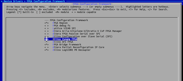
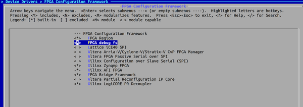
Zynq UltraScale+ MPSoC FPGA Manager Configuration:
Select: Device Drivers → FPGA Configuration Framework → Xilinx Zynq UltraScale+ MPSoC FPGA
In order to test readback feature user needs to enable FPGA debug fs
Select: Device Drivers → FPGA Configuration Framework --> FPGA debug fs
DT overlay ConfigFS Interface Configuration:
In order to load Bitstream with DTBO user needs to enable the below options
Select: Device Drivers --> Device Tree and Open Firmware support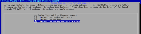
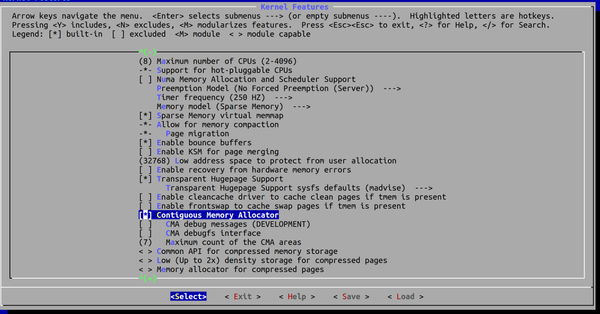
Contiguous Memory Allocator Configuration:
CONFIG_CMASelect: Kernel Features --> Contiguous Memory Allocator
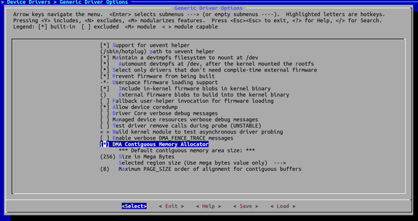
CONFIG_DMA_CMASelect: Device Drivers --> Generic Driver Options → DMA Contiguous Memory Allocator
Devicetree
| Code Block | ||
|---|---|---|
| ||
pcap {
       compatible = "xlnx,zynqmp-pcap-fpga";
       clocks = <&clk 41>;
};

fpga_full: fpga-full {
       compatible = "fpga-region";
       fpga-mgr = <&pcap>;
       #address-cells = <2>;
       #size-cells = <2>;
	   power-domains = <&zynqmp_firmware PL_PD>;
}; |
For more details about devicetree bindings Reference the Below link: Devicetree
Note: The above devicetree node is by default present in the zynqmp.dtsi file
Bitstream Format
From the 2018.3 release onwards FPGA Manager supports loading of vivado and bootgen generated Bitstream and Bin files vivadobootgen[1]
Note: For releases earlier to 2018.3 FPGA Manager was capable of loading only bootgen generated bin files. bootgen
.Bit Format
- Generated by Vivado
.Bin Format
- Generated by Vivado
- Generated by Bootgen by converting vivado generated bit file
Bootgen Command to generate bin file:
# bootgen -image Bitstream.bif -arch zynqmp -o ./Bitstream.bin -w (2018.1 or later releases)
# bootgen -image Bitstream.bif -arch zynqmp -process_Bitstream bin (2017.4 and earlier releases)
Bitstream.bif file should contains the below lines:
| Code Block | ||
|---|---|---|
| ||
all:
{
        [destination_device = pl] Full.bit (or)  Partial.bit /* Bitstream file name */
} |
Building Software Images
Xilinx tools (Petalinux, Yocto) provide an option with the name FPGA Manager which if enabled builds the device tree overlay fragments automatically and copies the Bitstream and DTBO files into root file system.
PetaLinux Flow
PetaLinux setup and build: PetaLinux
- Source the PetaLinux tool.source /opt/petalinux/petalinux-v<petalinux-version>/settings.sh
- Create a Versal template project or bsp project.
Code Block theme Midnight petalinux-create -t project -n zynqmp-dfx --template versalCode Block theme Midnight petalinux-create -t project -s <bsp path> -n zynqmp-dfx - Go to the project
Code Block theme Midnight cd zynqmp-dfx - Configure the project with static.xsa/base.xsa
Code Block theme Midnight petalinux-config --get-hw-description <base.xsa/static.xsa> - Enable FPGA manager using the following command
Code Block theme Midnight petalinux-config -> FPGA MANAGER - Create the static/base application using the following command from static/base xsa
Code Block theme Midnight petalinux-create -t apps --template fpgamanager_dtg -n <static-app> --enable --srcuri "<static xsa>"The previous command creates and packages the static dtbo and pdi files into the rootfs (/lib/firmware/xilinx/) using fpgamanager_dtg template.
- Create the partial application to configure the partial region using the rm xsa in the following command. You should point static pl app name as
--static-pncommand line option to define the relation between base and partial.Code Block petalinux-create -t apps --template fpgamanager_dtg_dfx -n <rm-app> --enable --srcuri <rm.xsa>" --static-pn <static-app>This command generates and packages the rm dtbo, pdi files into the rootfs (/lib/firmware/xilinx/<static-app>/<rm-app>).
- Execute
Code Block theme Midnight petalinux-buildThe command generates the rootfs containing both static and rprm dtbos, and respective pdi files as mentioned in the step 5 and step 6.
Once the base boot images ready with the previous step, if you want to build only DFX apps, use the commands mentioned in step 8.
- Execute the following command:
Code Block theme Midnight petalinux-build -c <static-app> petalinux-build -c <rm-app> in below path you will see with the below names. in <TMPDIR>/deploy/rpm you will see <static-app>.rpm and <rm-app>.rpmFor more details relevant to the above steps refer to this link: Petalinux-DFX-Support
Once the build is complete, binaries are available at images/linux directory.
- Boot the hardware with newly built images
- Directory /lib/firmware in the rootfs contains the Bitstreams and dtbo files
Yocto Flow
Yocto setup and build: yocto
Once Yocto environment is set
- Edit <yocto-proj-root>/build/conf/local.conf add below lines of code
| Code Block | ||
|---|---|---|
| ||
EXTRA_IMAGE_FEATURES += " fpga-manager"
EXTRA_HDF = "<PATH_TO_HDF_or_XSA>" |
Note:
- By default, it will pack base hdf Bitstream and dtbo to the /lib/firmware/base in the rootfs
- Extra hdf path can contain multiple HDF's
2. Build the required images (run the below command)
| Code Block | ||
|---|---|---|
| ||
$ bitbake petalinux-image-minimal |
Once the build is complete, binaries are available at ${DEPLOY_DIR_IMAGE} (${TMPDIR}/deploy/images/${MACHINE}/) directory
3. Boot the hardware with newly built images
- Directory /lib/firmware in the rootfs contains the Bitstreams and dtbo files
OSL Flow
Setup and Build: OSL
Images required for testing the FPGA Manager
- Bin/Bit file
- DTBO file
DTBO File Generation:
- Steps to Create the DT-Overlay Fragment
- Clone the device-tree-xlnx repo:
git clone device-tree-xlnx.git - Helper script: dt_overlay.tcl
- Command: # xsct dt_overaly.tcl system.hdf psu_cortexa53_0 device-tree-xlnx output_dir
- Clone the device-tree-xlnx repo:
Ex: xsct dt_overaly.tcl system.hdf psu_cortexa53_0 ${DTS_REPO}/device-tree-xlnx overlay
2. Create DeviceTree Overlay Blob (.dtbo) file from the pl.dtsi file
# dtc -O dtb -o pl.dtbo -b 0 -@ pl.dtsi
Ex: ./scripts/dtc/dtc -O dtb -o pl.dtbo -b 0 -@ pl.dtsi
3. Copy the generated bit and dtbo files to target
Note: PL nodes should not be the part of Base Device-tree (system.dtb).
- If the PL nodes are part of static dtb (system.dtb), these nodes cannot be removed at run-time.
FPGA programming
- Linux FPGA Manager framework provides sysfs (Bitstream loading), debugfs (readback), configfs (Bitstream loading along with DTBO for PL drivers) attributes.
- Alternatively, users can opt for Xilinx developed fpgautil. This utility provides an easy-to-use interface for programmers for all FPGA Manager use cases.
Exercising FPGA programming using fpgautil
Source code for the fpgautil is available in below meta layers.
| Info |
|---|
Note: In 2022.1 release fpgautil source code is moved from meta-xilinx-tools to meta-xilinx/meta-xilinx-core layer. |
2022.1 and later release: https://github.com/Xilinx/meta-xilinx/blob/master/meta-xilinx-core/recipes-bsp/fpga-manager-script/files/fpgautil.c
2021.2 and earlier release: https://github.com/Xilinx/meta-xilinx-tools/blob/rel-v2021.2/recipes-bsp/fpga-manager-script/files/fpgautil.c
| Code Block | ||
|---|---|---|
| ||
root@xilinx-zcu102-2018_3:~# fpgautil -h

fpgautil: FPGA Utility for Loading/reading PL Configuration in zynqMP

Usage:  fpgautil -b <bin file path> -o <dtbo file path>

Options: -b <binfile>           (Bin file path)
         -o <dtbofile>          (DTBO file path)
         -f <flags>             Optional: <Bitstream type flags>
                                   f := <Full | Partial >
                                Default: <Full>
          -s <secure flags>     Optional: <Secure flags>
                                   s := <AuthDDR | AuthOCM | EnUsrKey | EnDevKey | AuthEnUsrKeyDDR | AuthEnUsrK>
          -k <AesKey>           Optional: <AES User Key>
          -r <Readback>         Optional: <file name>
                                Default: By default Read back contents will be stored in readback.bin file
          -t                    Optional: <Readback Type>
                                   0 - Configuration Register readback
                                   1 - Configuration Data Frames readback
                                Default: 0 (Configuration register readback)
          -R                    Optional: Remove overlay from a live tree

Examples:
(Load Full Bitstream using Overlay)
fpgautil -b top.bin -o can.dtbo
(Load Partial Bitstream through the sysfs interface)
fpgautil -b top.bin -f Partial
(Load Authenticated Bitstream through the sysfs interface)
fpgautil -b top.bin -f Full -s AuthDDR
(Load Parital Encrypted Userkey Bitstream using Overlay)
fpgautil -b top.bin -o pl.dtbo -f Partial -s EnUsrKey -k <32byte key value>
(Read PL Configuration Registers)
fpgautil -b top.bin -r |
Fpgautil usage for DFx (aka PR/RP)use cases
Typical topology: FPGA has the base FPGA Region(static) with two PR/DFx regions (Each PR region has two RMs). The relevant files can be looked as below.
-- xilinx
    `-- static
        |-- static.dtbo
        |-- static.bin
        |---PR0
        |   `-- PR0-RM0
        |        |-- pr0-rm0.dtsi
        |        |-- pr0-rm0.dtbo
        |        |-- pr0-rm0.bin
        |    `-- PR0-RM1
        |        |-- pr0-rm1.dtsi
        |        |-- pr0-rm1.dtbo
        |        |-- pr0-rm1.bin
        |---PR1
        |   `-- PR1-RM0
        |       |-- pr1-rm0.dtsi
        |       |-- pr1-rm0.dtbo
        |       |-- pr1-rm0.bin
        |   `-- PR0-RM1
        |       |-- pr1-rm1.dtsi
        |       |-- pr1-rm1.dtbo
        |       |-- pr1-rm1.bin
- Configure/Reconfigure Static region using fpgautil: fpgautil -b <full/static bitstream image> -o <Full/static dtbo file> -f Full -n <Fpga region info>
- Usage example: fpgautil -b static.bin -o static.dtbo -f Full -n Full
- PR0 region configuration/Reconfigure using fpgautil:
- Command to configure the PR0-RM0 Image: fpgautil -b <PR0-RM0 Bitstream image> -o <PR0-RM0 dtbo file> -f Partial -n <Fpga region info>
- Usage example: fpgautil PR0-RM0.bin -o PR0-RM0.dtbo -f Partial -n PR0
- Command to Remove Images(PR0-RM0) from the PR0 region: fpgautil -R -n -n <Fpga region info> (Note: Before Reconfiguring the same region with a different Bitstream user needs to remove the existing dtbo relevant to it)
- Usage example: fpgautil -R -n PR0
- Command to configure the PR0-RM1 Image:: fpgautil -b <PR0-RM1 Bitstream image> -o <PR0-RM1 dtbo file> -f Partial -n <Fpga region info>
- Usage example: fpgautil PR0-RM1.bin -o PR0-RM1.dtbo -f Partial -n PR0
- Command to Remove Images(PR0-RM1) from the PR0 region: fpgautil -R -n <Fpga region info>
- Usage example: fpgautil -R -n PR0
- Command to configure the PR0-RM0 Image: fpgautil -b <PR0-RM0 Bitstream image> -o <PR0-RM0 dtbo file> -f Partial -n <Fpga region info>
- PR1 region configuration/reconfiguration using fpgautil:
- Command to configure the PR0-RM0 Image: fpgautil -b <PR1-RM0 Bitstream image> -o <PR1-RM0 dtbo file> -f Partial -n <Fpga region info>
- Usage example: fpgautil PR1-RM0.bin -o PR1-RM0.dtbo -f Partial -n PR1
- Command to Remove Images(PR1-RM0) from the PR1 region: fpgautil -R -n <Fpga region info> (Note: Before Reconfiguring the same region with a different Bitstream user needs to remove the existing dtbo relevant to it)
- Usage example: fpgautil -R -n PR1
- Command to configure the PR1-RM1 Image:: fpgautil -b <PR1-RM1 Bitstream image> -o <PR1-RM1 dtbo file> -f Partial -n <Fpga region info>
- Usage example: fpgautil PR1-RM1.bin -o PR1-RM1.dtbo -f Partial -n PR0
- Command to Remove Images(PR0-RM1) from the PR0 region: fpgautil -R -n <Fpga region info>
- Usage example: fpgautil -R -n PR1
- Command to configure the PR0-RM0 Image: fpgautil -b <PR1-RM0 Bitstream image> -o <PR1-RM0 dtbo file> -f Partial -n <Fpga region info>
- Command to remove the images from the static region: fpgautil -R -n <Fpga region info>
- Usage example: fpgautil -R -n Full
Notes:
- Before Reconfiguring the same region(whether it is a static/ partial region) with a different Bitstream user needs to remove the existing dtbo relevant to it
Fpgautil -R is responsible for only removing the dtbo file from the livetree. it will not remove the PL logic from the FPGA region. If the user wants to remove the complete configuration logic from the FPGA region he should reconfigure the target configuration region with grey-box logic.
Loading an overlay along with it's Bitstream
...
| Code Block | ||
|---|---|---|
| ||
root@xilinx-zcu102-2018_3:~# root@xilinx-zcu102-2018_3:~# fpgautil -b /lib/firmware/design_1_wrapper/design_1_wrapper.bit.bin -o /lib/firmwaree/design_1_wrapper/design_1_wrapper.dtbo [ 43.642776] fpga_manager fpga0: writing design_1_wrapper.bit.bin to Xilinx ZynqMP FPGA Manager [ 43.871149] XGpio: /amba/gpio@a0000000: registered, base is 298 [ 43.877420] XGpio: /amba/gpio@a0000000: dual channel registered, base is 290 Time taken to load DTBO is 244.000000 Milli Seconds DTBO loaded through zynqMP FPGA manager successfully root@xilinx-zcu102-2018_3:~# root@xilinx-zcu102-2018_3:/sys/class/gpio# dmesg |grep gpio [ 5.399518] input: gpio-keys as /devices/platform/gpio-keys/input/input0 [ 43.871149] XGpio: /amba/gpio@a0000000: registered, base is 298 [ 43.877420] XGpio: /amba/gpio@a0000000: dual channel registered, base is 290 root@xilinx-zcu102-2018_3:/sys/class/gpio# dmesg |grep gpio [ 5.399518] input: gpio-keys as /devices/platform/gpio-keys/input/input0 [ 43.871149] XGpio: /amba/gpio@a0000000: registered, base is 298 [ 43.877420] XGpio: /amba/gpio@a0000000: dual channel registered, base is 290 root@xilinx-zcu102-2018_3:/sys/class/gpio# echo 290 > export root@xilinx-zcu102-2018_3:/sys/class/gpio# cd gpio290 root@xilinx-zcu102-2018_3:/sys/class/gpio/gpio290# ls active_low device direction edge power subsystem uevent value root@xilinx-zcu102-2018_3:/sys/class/gpio/gpio290# echo 1 out > direction root@xilinx-zcu102-2018_3:/sys/class/gpio/gpio290# echo 0 > value root@xilinx-zcu102-2018_3:/sys/class/gpio/gpio290# echo 1 > value root@xilinx-zcu102-2018_3:/sys/class/gpio/gpio290# |
...
| Code Block | ||
|---|---|---|
| ||
root@xilinx-zcu102-2018_3:~# fpgautil -b pr1rm1.bit.bin -f Partial
Flags : 0x1
Time taken to load BIN is 56.000000 Milli Seconds
BIN FILE loaded through zynqMP FPGA manager successfully |
...
| Code Block | ||
|---|---|---|
| ||
root@xilinx-zcu102-2018_3:~# fpgautil -r readbackdata -t 1 root@xilinx-zcu102-2018_3:~# hexdump readbackdata.bin > data.txt |
Verification of Read-back Data
To verify the readback data stream, compare it to the RBD golden readback file and masking readback bits with the MSD file. This approach is simple because there is a 1:1 correspondence between the start of the readback data stream and the start of the RBD and MSD files, making the task of aligning readback, mask, and expected data easier.
The RBD and MSD files contain an ASCII representation of the readback and mask data along with a file header that lists the file name, etc. This header information should be ignored or deleted. The ASCII 1s and 0s in the RBD and MSD files correspond to the binary readback data from the device.
For generating RBD and MSD refer UG908 (Vivado Design Suite User Guide)
By compiling the below utility(verify_readback.c file) user can verify the read back contents.
Source code: verify_readback
...
Steps for programming the Full Bitstream
Set flags for Full Bitstream
- echo 0 > /sys/class/fpga_manager/fpga0/flags
...
mkdir -p /lib/firmware
cp /media/design_1_wrapper.bit.bin /lib/firmware/
echo design_1_wrapper.bit.bin > /sys/class/fpga_manager/fpga0/firmware
Steps for programming the Partial Bitstream
Set flags for Partial Bitstream
- echo 1 > /sys/class/fpga_manager/fpga0/flags
Load the Bitstream Partial Bitstream
mkdir -p /lib/firmware
cp /media/partail_wrapper.bit.bin /lib/firmware/
echo partail_wrapper.bit.bin > /sys/class/fpga_manager/fpga0/firmware
...
Steps for Readback of Configuration Registers
Set flags for readback type
...
Steps for Readback of Configuration DataFrames
Set flags for readback type
...
- Target FPGA Region
- "target-path" or "target" - The insertion point where the the contents of the overlay will go into the live tree.
target-path is a full path, while target is a phandle. - FPGA Image firmware file name
- "firmware-name" - Specifies the name of the FPGA image file on the firmware search path.
The search path is described in the firmware class documentation. - Image specific information
- external-fpga-config : boolean, set if the FPGA has already been configured prior to Linux boot up. - Child devices
- child nodes corresponding to hardware that will be loaded in this region of the FPGA.region of the FPGA.
| Warning |
|---|
Notes:
|
Steps for programming the Full Bitstream using overlay
...
| Code Block | ||
|---|---|---|
| ||
//Device Tree Example: Full Reconfiguration along with PS PL Configuration (Clock, resets and AFI)
// HSI Generated overlay/pl.dtsi file.
// Enable the axi-gpio interface
/dts-v1/;
/plugin/;
/ {
	fragment@0 { /* Bitstream  Fragment */
		target = <&fpga_full>;
		overlay0: __overlay__ {
			#address-cells = <2>;
			#size-cells = <2>;
			firmware-name = "design_1_wrapper.bit.bin";
			resets = <&rst 116>;
		};
	};
	fragment@1 { /* PS-PL configuration Fragment */
		target = <&amba>;
		overlay1: __overlay__ {
			afi0: afi0 {
				compatible = "xlnx,afi-fpga";
				config-afi = < 0 0>, <1 0>, <2 0>, <3 0>, <4 0>, <5 0>, <6 0>, <7 0>, <8 0>, <9 0>, <10 0>, <11 0>, <12 0>, <13 0>, <14 0>, <14 0>, <15 0x000>;
			};
			clocking0: clocking0 {
				#clock-cells = <0>;
				assigned-clock-rates = <99990005>;
				assigned-clocks = <&clk 71>;
				clock-output-names = "fabric_clk";
				clocks = <&clk 71>;
				compatible = "xlnx,fclk";
			};
		};
	};
	fragment@2 { /* PL Drivers Fragment */
		target = <&amba>;
		overlay2: __overlay__ {
			axi_gpio_0: gpio@a0000000 {
				#gpio-cells = <3>;
				#interrupt-cells = <2>;
				clock-names = "s_axi_aclk";
				clocks = <&clk 71>;
				compatible = "xlnx,axi-gpio-2.0", "xlnx,xps-gpio-1.00.a";
				gpio-controller ;
				interrupt-controller ;
				interrupt-names = "ip2intc_irpt";
				interrupt-parent = <&gic>;
				interrupts = <0 89 4>;
				reg = <0x0 0xa0000000 0x0 0x1000>;
				xlnx,all-inputs = <0x1>;
				xlnx,all-inputs-2 = <0x0>;
				xlnx,all-outputs = <0x0>;
				xlnx,all-outputs-2 = <0x1>;
				xlnx,dout-default = <0x00000000>;
				xlnx,dout-default-2 = <0xAAAAAAAA>;
				xlnx,gpio-width = <0x8>;
				xlnx,gpio2-width = <0x8>;
				xlnx,interrupt-present = <0x1>;
				xlnx,is-dual = <0x1>;
				xlnx,tri-default = <0xFFFFFFFF>;
				xlnx,tri-default-2 = <0xFFFFFFFF>;
			};
			psu_ctrl_ipi: PERIPHERAL@ff380000 {
				/* This is a place holder node for a custom IP, user may need to update the entries */
				compatible = "xlnx,PERIPHERAL-1.0";
				reg = <0x0 0xff380000 0x0 0x80000>;
			};
			psu_message_buffers: PERIPHERAL@ff990000 {
				/* This is a place holder node for a custom IP, user may need to update the entries */
				compatible = "xlnx,PERIPHERAL-1.0";
				reg = <0x0 0xff990000 0x0 0x10000>;
			};
		};
	};
};
|
Working with Device Tree Overlay (DTBO)
Copy the Partial Bitstream (.bin) and rm.dtbo files into lib/firmware folder
mkdir /configfs
mount -t configfs configfs /configfs
cd /configfs/device-tree/overlays/
mkdir partial
- echo 1 > /sys/class/fpga_manager/fpga0/flags
echo -n "pl.dtbo" > partial/path
To remove a device tree overlay:
- rmdir /configfs/device-tree/overlays/partial
Exercising FPGA programming using Libdfx
Refer this link: libdfx - Linux User Space Solution for FPGA Programming
Mainline Status
The current driver availble in the xilinx linux git is in sync with the open source 4.19 kernel driver except for the following
- Encrypted and Authenticated Full/Partial Bitstream loading
- Readback of Configuration Registers
- Readback of Bitstream(Configuration Data)
...
 the entries */
				compatible = "xlnx,PERIPHERAL-1.0";
				reg = <0x0 0xff990000 0x0 0x10000>;
			};
		};
	};
};
|
Working with Device Tree Overlay (DTBO)
Copy the Partial Bitstream (.bin) and rm.dtbo files into lib/firmware folder
mkdir /configfs
mount -t configfs configfs /configfs
cd /configfs/device-tree/overlays/
mkdir partial
- echo 1 > /sys/class/fpga_manager/fpga0/flags
echo -n "pl.dtbo" > partial/path
To remove a device tree overlay:
- rmdir /configfs/device-tree/overlays/partial
Exercising FPGA programming using Libdfx
Refer this link: libdfx - Linux User Space Solution for FPGA Programming
Mainline Status
The current driver availble in the xilinx linux git is in sync with the open source 6.6 kernel driver except for the following
- Encrypted and Authenticated Full/Partial Bitstream loading
- Readback of Configuration Registers
- Readback of Bitstream(Configuration Data)
- Use the scatterlist interface
Release history
2023.2
- Revert "fpga: zynqmp: Initialized variables before using it"
2023.1
- FPGA Manager framework upgraded to 6.1v
2022.3
- None.
2022.2
- fpga: zynqmp: Add feature-list validation check
- firmware: xilinx: Update the zynqmp_pm_fpga_load() API
- fpga: zynqmp-fpga: Remove empty function
- fpga: zynqmp: Make word align the configuration data
2022.1
FPGA Manager framework upgraded to 5.15v
2021.2
- None
2021.1
FPGA Manager framework upgraded to 5.10v
2020.2
Summary:
- fpga: zynqmp: Use the scatterlist interface
- fpga: zynqmp: Initialized variables before using it
- fpga: zynqmp: Fix incorrect variables type
Commits:
- 4823227 fpga: zynqmp: Use the scatterlist interface
- aac8be7 fpga: zynqmp: Initialized variables before using it
- 2899bc8 fpga: zynqmp: Fix incorrect variables type
2020.1
- None
2019.2
Summary:
- fpga: zynqmp-fpga: Adds status interface
Commits:
- 8e85861 fpga: zynqmp-fpga: Adds status interface
2019.1
Summary:
- fpga: Fix bitstream typo error
- Merge tag 'v4.19' into master
- fpga: ZynqMP: Adds support for Authentication of bitstreams usning User-key
- drivers: xilinx: Reorganize firmware driver for zynqmp
- drivers: Defer probe if firmware is not ready
- fpga: zynqmp: Revert Authentication of bitstreams using User-key changes
- fpga: zynqmp: Use SPDX license header
...
- Added support for vivado generated bit and bin file loading
- Added support for PL configuration readback
- Added support for clock framework
Commits:
- daca3d fpga: zynqmp: Adds support to load vivado generated .bit and .bin files
- bd1f10 fpga: zynqmp-fpga: Add support for pl configuration readback
- 097ea7 fpga: zynqmp-fpga: Add support for clock framework
2018.2
Summary:
- Added Support for Partial Reconfiguration
...