...
Open the Address editor and unmap (right click and select unmap segment) on the GP0_DDR_LOWOCM, GP0_QSPI_LINEAR and GP0_M_AXI_GP0:
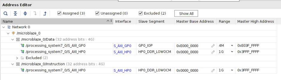

Note: change the range to 4K first, then change the base address to 0x0010_0000. Then, change the range to 256MB (or whatever size you need).
Software Generation:
Create FSBL:
Select File -> New -> Application Project. Set the Project Name to "fsbl", and the Processor to "ps7_cortexa9_0" and select Next. Select the Zynq FSBL and Finish.
FSBL Modification:
We can add the debug to the FSBL (this is optional). To do this, right click on the fsbl in the Project explorer and select C/C++ Build Settings and add the FSBL_DEBUG_INFO to the compiler symbol: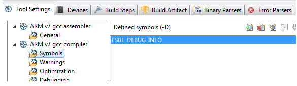
Next, open the fsbl_hooks.c from fsbl/src in the Project Explorer, and add the code to toggle the GPIO that we added in the Hardware. You can add the register writes seen below to the FsblHookFallback function: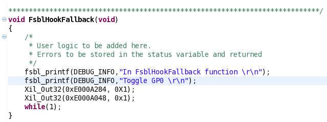
Right click on the FSBL, and select Generate Linker Script, and place all sections in ps7_ram_0 and Generate.
Create Microblaze Hello World Application:
Create the MicroBlaze Hello World Application. Select New -> Application Project. Set the Project Name to "hello", and the Processor to "microblaze_0" and select Next. Select the Hello World and Finish. This will automatically create the BSP. The BSP will use the PS7_UART_1 for STDIN/OUT as we have connected the DP interface on the MicroBlaze to the GP port which allows access to PS IP (including the UART). Generate the Linker script for this application and make sure all sections are in the DDR.
Note: Both the MicroBlaze app and the FSBL are sharing the same ps7_uart_1. Be aware that if both processors try to write at the same time, you might see issues.
Note: The linker script will automatically be created based on the memory settings detected in the XSA. In this case, the DDR i set to 0x0010_0000:

Boot Image Creation:
Here, we will be booting from the SD card. To create a BIN image for the SD card, use the Create Boot Image tool in the SDK. Right click on the FSBL, and select Create Boot Image. The FSBL and the BIT should be pre-populated. If not, then you can add these manually using the Add button in the GUI.
Note: the FSBL partition type is bootloader, all other partitions are datafile. Add the hello.elf (select Add, and browse to the hello.elf. The partition type is datafile):
Select Create Image to create the BOOT.BIN file.
Booting from SD Card:
Place this BOOT.bin file onto the SD card, and set the bootmode to boot from the SD card and power on the board. You will see the FSBL debug information, and the Hello World App: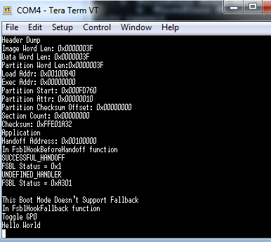
Debugging in Vitis:
...