Zynq UltraScale+ MPSoC Base TRD 2018.3 - Design Module 7
Table of Contents
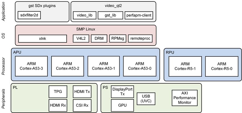
Design Overview
This module shows how to add a 2D convolution filter between the capture pipeline and the display. The 2D filter is implemented in two ways:
- software implementation using the OpenCV library
- hardware-optimized implementation which is run in software. The next module shows how to accelerate this code using FPGA logic.
Design Components
This module requires the following components:
- zcu102_base_trd (SDSoC)
- sdxfilter2d (gstreamer plugin)
Build Flow Tutorials
2D Filter GStreamer Plugin
This tutorial shows how to build the 2D Filter Gstreamer Plugin without HW acceleration based on the Base TRD SDSoC platform.
Create a new workspace for the sdx gstreamer plugin projects.
% mkdir -p $TRD_HOME/workspaces/ws_sdx
% cd $TRD_HOME/workspaces/ws_sdx
% sdx -workspace . &
- Click 'Create Library Project' from the welcome screen, enter
gstsdxfilter2das project name and click 'Next'.
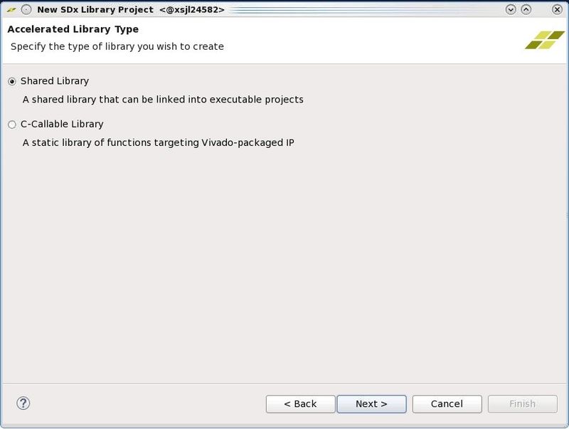
- Select 'Shared Library' and click 'Next'.
- Click the plus sign to add a custom platform, browse to the
$TRD_HOME/zcu102_base_trdfolder and click OK. Select the "zcu102_base_trd [custom]" platform from the list and click 'Next'.
- Keep the default settings, check the "Linux Root File System" box, click browse and enter the path to the petalinux generated target sysroot:
$TRD_HOME/petalinux/sdk/sysroots/aarch64-xilinx-linux
- Select the "GStreamer Filter 2D Plugin" from the Templates dialog and click 'Finish'.

- In the "Application Project Settings" panel, set the active build configuration to "Release" and remove the pre-selected Hardware Functions by clicking the red 'X' symbol until the pane is empty. Make sure the 'Generate SD card image' box is checked.

Right-click the
gstsdxfilter2dproject in the explorer pane and select 'Build Project'. This should take less than a minute.Copy the generated SD card image once the build is finished
% cp -r gstsdxfilter2d/Release/sd_card $TRD_HOME/sd_card/dm7
Run Flow Tutorial
- See here for board setup instructions.
- Copy all the files from the $TRD_HOME/sd_card/dm7 SD card directory to a FAT formatted SD card.
- Power on the board to boot the images; make sure INIT_B, done and all power rail LEDs are lit green.
- After ~30 seconds, the display will turn on and the application will start automatically, targeting the max supported resolution of the monitor (one of 3840x2160 or 1920x1080 or 1280x720). The application will detect whether DP Tx or HDMI Tx is connected and output on the corresponding display device.
To re-start the TRD application with the max supported resolution, run
% run_video.sh
To re-start the TRD application with a specific supported resolution use the -r switch e.g. for 1920x1080, run
% run_video.sh -r 1920x1080
- The user can now control the application from the GUI's control bar (bottom) displayed on the monitor.
- The user can select from the following video source options:
- TPG (SW): virtual video device that emulates a USB webcam purely in software
- USB: USB Webcam using the universal video class (UVC) driver
- TPG (PL): Test Pattern Generator implemented in the PL
- HDMI: HDMI input implemented in the PL
- CSI: MIPI CSI image sensor input implemented in PL
- File: Raw video file source
- The user can select from the following accelerator options:
- Passthrough (no accelerator)
- 2D convolution filter with configurable coefficients
- A 2D convolution filter can be turned on and different filter presets can be selected; the following filter modes are available:
- SW - accelerator is run on A53 using OpenCV implementation
- HW - hardware optimized accelerator code run on A53
Note: This performs slower than the OpenCV version of the implementation which is expected since the code is optimized to be synthesized to FPGA logic

- The video info panel (top left) shows essential settings/statistics.
- The CPU utilization graph (top right) shows CPU load for each of the four A53 cores.
Next Steps
- Continue with Design Module 8.
- Return to the Design Tutorials Overview.
© Copyright 2019 - 2022 Xilinx Inc. Privacy Policy