Zynq-7000 XADC to PS App Note
Table of Contents
1 Introduction
This page provides instructions on how to build various components of the ZC702 Xilinx Analog to Digital Converter (XADC) to Processing System (PS) dedicated interface application note and how to setup the hardware platform and run the design on the ZC702 Evaluation Kit. The ZC702 Evaluation kit is based on a XC7Z020 CLG484-1 Zynq-7000 SoC device. For additional information, refer to XAPP11721.1 About the ZC702 XADC to PS Application Note
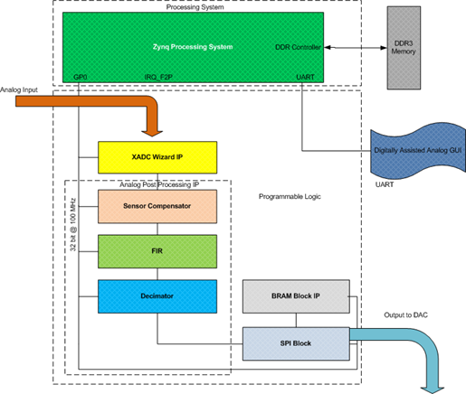
The Zynq-7000 PS has a dedicated interface to the XADC, two integrated 12-bit, 1Msps analog to digital converters supporting on chip voltage and temperature measurements and 17 external channels. The XADC is a hard block offered in all Zynq-7000 SoCs. The XADC to PS interface enables a reliable system monitoring capability in Zynq-7000, without requiring the need to enable the Programmable Logic. This interface allows monitoring of both internal (voltage sensors and temperature) and external signals such as on-board voltages, currents or other environmental sensors. Alarms and warning signals can be set for conditions such as over-temperature and over/under-voltage conditions, giving users a more complete perspective of the conditions surrounding the Zynq-7000 SoC.Significant system power savings can be achieved by powering up the PS logic along with XADC when required.
The communication between the PS and the XADC block happens through JTAG interface. The command from PS is stored in a command FIFO using APB interface and then serialized using a parallel-to-serial converter. The serialized data is then sent over TDO pin (port) of the JTAG interface. The JTAG clock is generated in the Zynq-7000 PS subsystem. The incoming serial data from XADC is parallelized using a serial-to-parallel converter. The parallel data is stored in a data FIFO and then read out by the PS using APB interface. For more information on Zynq-7000 XADC to PS interface, please refer to Zynq-7000 SoC Technical Reference Manual, UG585.
Note that while the XADC to PS interface is in use, the user will not be able to use the external JTAG interface to access the XADC registers.
For more details on XADC please refer chapter 30 of Zynq-7000 TRM (ref link).
The focus of this application note is to showcase system monitoring feature of Zynq-7000 devices implemented using dedicated XADC to PS interface.
This application note achieves the following: of this application note are:
- It showcases how to quickly establish an interface between Zynq-7000 PS and XADC
- Presents an example code that covers the typical system monitoring use cases including alarms
- Evaluate the XADC’s performance of the XADC to PS interface
1.2 Package Content
The XAPP1172 package contains the following:- XAPP1172 Linux Software based Application C code for command line
- Webserver based Linux application XSDK project
- Common library / XADC core implementation
- Pre-built SD images for out-of-box user experience
- Readme file
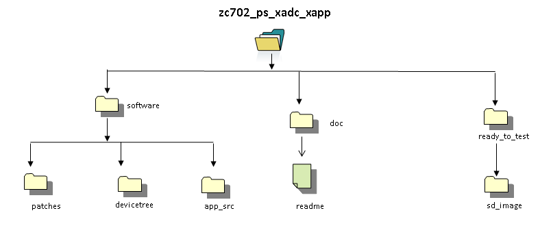
The following Figure shows the directory structure tree.
2 Prerequisites
- The ZC702 Evaluation Kit ships with the version 14.x Device-locked to the Zynq-7000 XC7Z020 CLG484-1 device and all required licenses to build the application note. For additional information, refer to UG798 ISE Design Suite 14: Installation and Licensing Guide.
- A Linux development PC with the ARM GNU tools installed. The ARM GNU tools are included with the Xilinx ISE Design Suite Embedded Edition or can be downloaded separately.
- A Linux development PC with the distributed version control system Git installed. For more information, refer to Using Git and to UG821: Xilinx Zynq-7000 EPP Software Developers Guide.
Tools Required
Tools for Software build
- Windows XP/Windows7
- SDK 14.5
For building Linux kernel and application of Zynq PS:
- ARM cross compile tool
- mkimage
- corkscrew
- git
From here onward lets consider the unzipped package is available at $ZYNQ_XADC_PS_HOME.
And let $ZYNQ_XADC_PS_HOME/workspace be the development area. Hence forth this area will be represented by $WORK_AREA
3 Building the FSBL
This section explains the steps for building the FSBL.- On Windows 7, select Start > All Programs > Xilinx Design Tools 14.5 > ISE Design Suite 14.5 > EDK > Xilinx Software Development Kit.
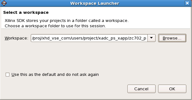
- On Linux, enter xsdk at the command prompt.In the Workspace Launcher window, click Browse and navigate to {{$}}ZYNQ_XADC_PS_HOME{{}}/software, then click OK. Close the welcome screen
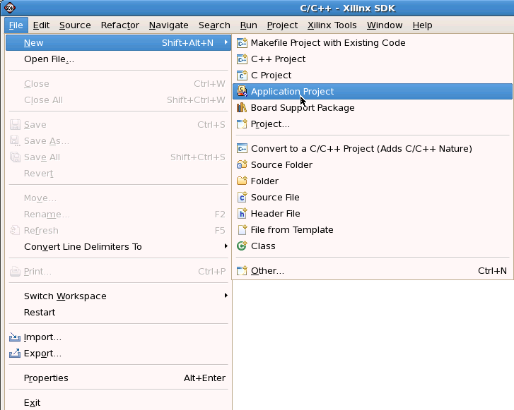
- Click on File -> New -> Application project
- Select ZC702 predefined Hardware Platform and click on Next.
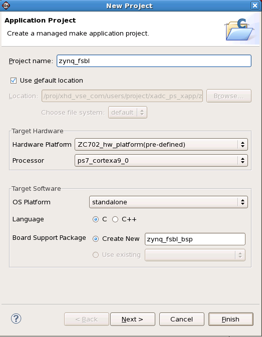
- Select Zynq FSBL and click on Finish
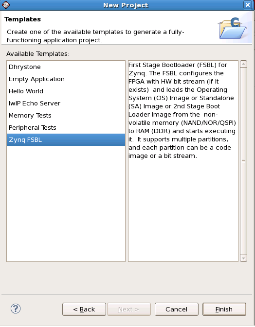
The final step will create the Zynq FSBL elf file
4 Building the U-boot Boot Loader
This section explains how to download the sources, configure, and build the U-boot boot loader for this app note. A pre-compiled U-boot executable can be found at $ZYNQ_XADC_PS_HOME/ready_to_test/boot_image/u-boot.elf. For additional information, refer to Xilinx Zynq U-boot. This step requires a Linux development PC with the ARM GNU tools and Git installed (see Section 2).Steps for building the U-boot boot loader
Set the CROSS_COMPILE environment variable and add it to your PATH.
bash> export CROSS_COMPILE=arm-xilinx-linux-gnueabi-
bash> export PATH=/path/to/cross/compiler/bin:$PATH
bash> cd $WORK_AREA
bash> git clone git://github.com/Xilinx/u-boot-xlnx.git
bash> cd $WORK_AREA/u-boot-xlnx
bash> git checkout -b zynq_xadc_ps xilinx-v14.5.01
bash> make ARCH=arm zynq_zc70x_config
bash> make ARCH=arm
bash> mv u-boot u-boot.elf
5 Building the Boot Image
This section explains how to create the boot image file- On Windows 7, select Start > All Programs > Xilinx Design Tools 14.5 > ISE Design Suite 14.5 > EDK > Xilinx Software Development Kit.
- On Linux, enter xsdk at the command prompt.In the Workspace Launcher window, click Browse and navigate to {{$}}ZYNQ_XADC_PS_HOME{{ }}/software, then click OK. Close the welcome screen
- Click on Xilinx Tools and select Create Zynq Boot Image option. Select appropriate Output folder location.
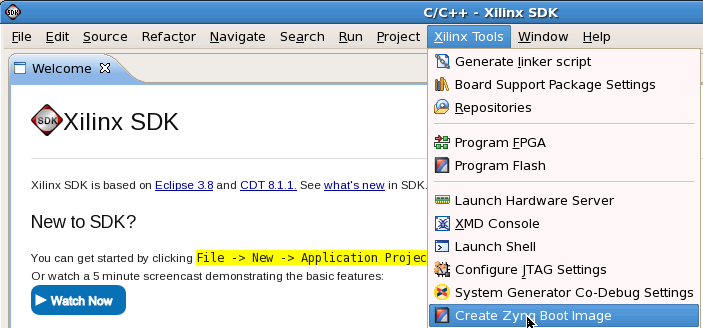
- Select FSBL and u-boot elf files.

- Click on Create Image
The final step creates the bin file in the Output folder location. Rename the file as BOOT.bin.
6 Building the Linux Kernel
This section explains how to download the sources, configure, patch, and build the Linux kernel for this app note. It also explains how to compile a device tree. For additional information, refer to the Xilinx Zynq Linux wiki. This step requires a Linux development PC with the ARM GNU tools and Git installed.6.1 Building the Linux Kernel Image
A pre-compiled Linux kernel can be found at $ZYNQ_XADC_PS_HOME/ready_to_test/sd_image/uImage.Steps for building the Linux kernel.
Set the CROSS_COMPILE environment variable and add it to your PATH.
bash> export CROSS_COMPILE=arm-xilinx-linux-gnueabi-
bash> export PATH=/path/to/cross/compiler/bin:$PATH
bash> export PATH=$WORK_AREA/u-boot-xlnx/tools:$PATH
bash> cd $WORK_AREA
bash> git clone git://github.com/Xilinx/linux-xlnx.git
bash> cd $WORK_AREA/linux-xlnx
bash> git checkout -b zynq_xadc_ps  xilinx-v14.5.01
Apply the App note specific patch on top of the xilinx-14.5.01 tag. The patch includes:
- IIO framework and IIO frameworked based XADC driver.
bash> cp $ZYNQ_XADC_PS_HOME/software/patches/zynq_ps_xadc.patch .            // copy the patch from package to dev area
bash> git apply --stat zynq_ps_xadc.patch                                    // display contents of patch
bash> git apply --check zynq_ps_xadc.patch                                   // check if patch can be applied

bash> git am zynq_ps_xadc.patch // apply the patch
bash> make ARCH=arm zynq_iio_xadc_defconfig
bash> make ARCH=arm uImage modules UIMAGE_LOADADDR=0x8000
6.2 Building the Linux Device Tree Blob
This step requires that the steps in Section 6.1 are completed first. A pre-compiled Device Tree Blob can be found at $ZYNQ_XADC_PS_HOME/ready_to_test/sd_image/devicetree.dtb.Steps for building the Linux device tree blob
Compile the Base TRD device tree file. The output of this step is a device tree blob and can be found at $ZYNQ_TRD_HOME/linux-xlnx/devicetree.dtb.
bash> ./scripts/dtc/dtc -I dts -O dtb -o devicetree.dtb ./arch/arm/boot/dts/zynq-zc702-xadc.dts
7 Hardware Setup Requirements
1. The ZC702 evaluation board with the XC7Z020 CLG484-1 part2. XAPP1172 zip file containing the design files and application executables2. Internet Explorer version 8.0 or aboveAMS101 evaluator card
3. Optional signal generator to test externally applied analog signal
4. Mini USB cable
5. Class 4 equivalent SD card
6. A control PC
8 Execution Steps
This section summarizes the execution steps of the XAPP on ZC702 platform.8.1 ZC702 Initial Setup
1. All jumpers and switches should be in default setting except SW16.Mode switch SW16 should be set to boot from SD card.
Use the following switch settings:
SW16.1: OFF
SW16.2: OFF
SW16.3: ON
SW16.4: ON
SW16.5: OFF
2. Connect the AC power adapter
3. If USB-to-UART bridge is used, connect USB Mini-B side of USB-to-Mini-B cable to the on-board mini USB connector (J17). Connect USB side to
the control PC.
4. Install SVG Viewer
5. Connect ethernet cable between Host PC and the Zynq Board via RJ45 cable. Make sure Host PC and Zynq are in same network domain.
Note: For static IP (through dts), the zynq having IP as 192.168.1.10; the host PC can have IP address 192.168.1.2
8.2 Webserver execution steps
1. Load the SD card with content of <pkg>/read_to_test/sd_image. Insert this SD cardin zynq board.
2. Power ON the zynq board and wait for few minutes
-- see the Linux booting in the uart terminal
-- After power up, the webserver starts automatically on background through init
script.
3. On Host machine open IE 8(or above) browser.
4. Type zynq ip with port number 9090 in the address bar fo browser
-- e.g. http://192.168.1.10:9090
5. Observe the senor values / graphs on the web page
6. Change threshold values to see the Alarm triggering and status change.
9 References
- User Guide for XAPP1172
- Documentation for Zynq-7000 SoC
- Documentation for ZC702 Evaluation Kit
- Main Xilinx wiki
© Copyright 2019 - 2022 Xilinx Inc. Privacy Policy