Zynq UltraScale MPSoC Base TRD 2018.2 - Design Module 2
Zynq UltraScale MPSoC Base TRD 2018.2 - Design Module 2
Table of Contents
Design Overview
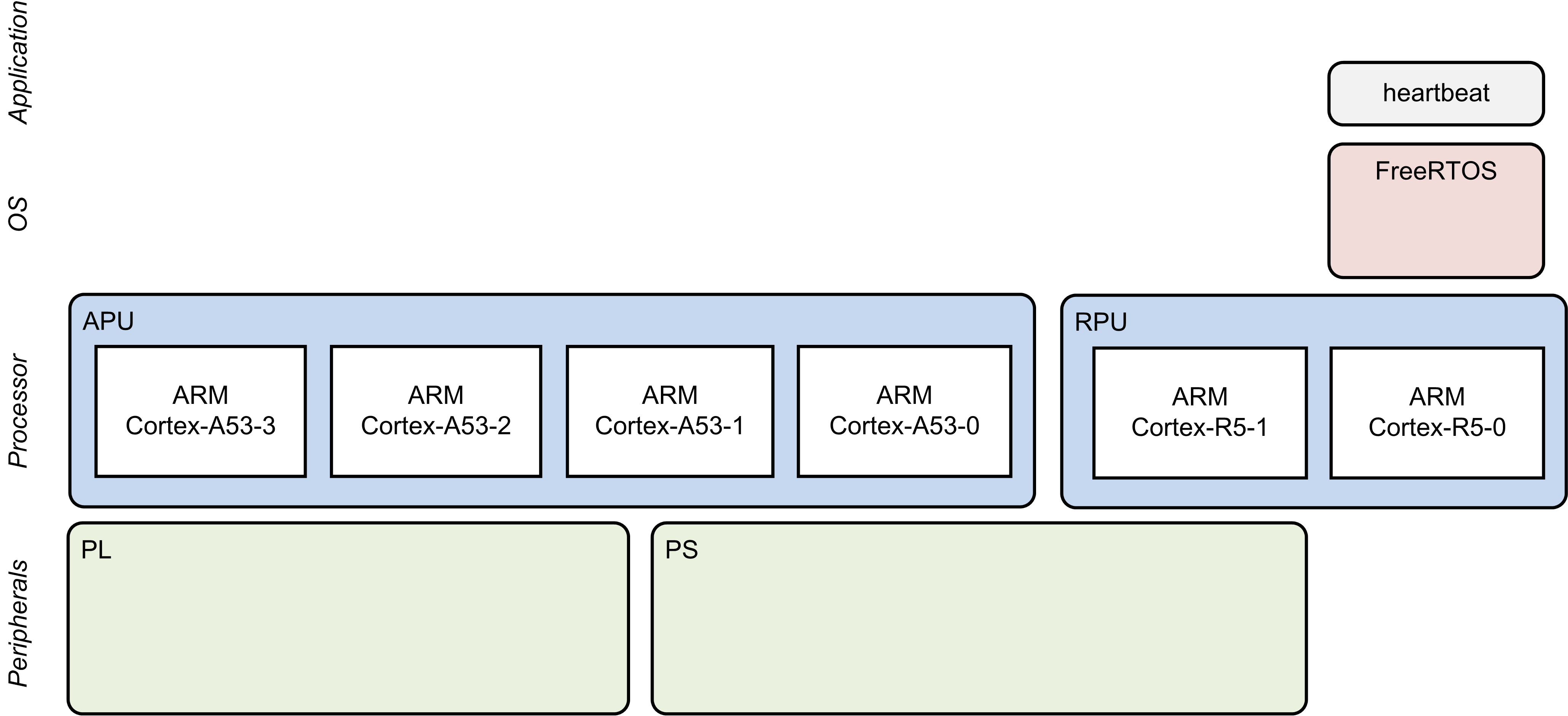
This design module demonstrates the FreeRTOS and application running on RPU-0, where:
- FreeRTOS boots on RPU-0
- FreeRTOS application "heartbeat" prints periodic messages on UART-1
Design Components
- petalinux_bsp
- zynqmp_fsbl
- pmufw
- heartbeat.elf
Build Flow Tutorials
This tutorial uses both XSDK and PetaLinux tools. It is recommended to use separate shells for each of the tools.
Heartbeat Application
The heartbeat application is a FreeRTOS application that executes on RPU-0 after the FSBL has finished. This application is a simple dual task application that demonstrates communication between the two tasks by printing messages to the UART1 console.
- Create a new SDx workspace.
% cd $TRD_HOME/workspaces/ws_heartbeat
% xsdk -workspace . &&
- Click 'Import Project' from the welcome screen, browse to the current working directory and make sure the heartbeat, heartbeat_bsp, and hw_platform_0 projects are selected. Click Finish.
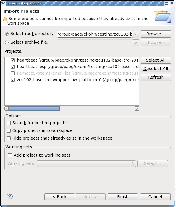
- Right-click on the heartbeat project and select 'Build Project'.
- Copy the generated heartbeat executable into the PetaLinux BSP.
cp heartbeat/Debug/heartbeat.elf $TRD_HOME/petalinux/bsp/images/linux
PetaLinux BSP
This tutorial shows how to build a boot image that includes the heartbeat application using the PetaLinux build tool. This step assumes you have run through the PetaLinux build in DM1 previously.
- Create a boot image.
% cd $TRD_HOME/petalinux/bsp/images/linux
% petalinux-package --boot --bif=../../project-spec/boot/dm2.bif --force
- Copy the generated boot image to the dm2 SD card directory.
% mkdir -p $TRD_HOME/sd_card/dm2
% cp BOOT.BIN $TRD_HOME/sd_card/dm2
Run Flow Tutorial
- See here for board setup instructions.
- Copy all the files from the $TRD_HOME/sd_card/dm2 SD card directory to a FAT formatted SD card.
- Power on the board to boot the images; make sure all power rail LEDs are lit green.
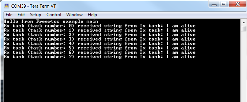
- The user can now see FSBL prints on UART-0 and prints from heartbeat application can be viewed on UART-1 which is shown in the following picture:
Continue with Design Module 3.
Return to the Design Tutorials Overview.
© Copyright 2019 - 2022 Xilinx Inc. Privacy Policy