Zynq UltraScale+ MPSoC Base TRD 2019.1 - Design Module 9
Table of Contents
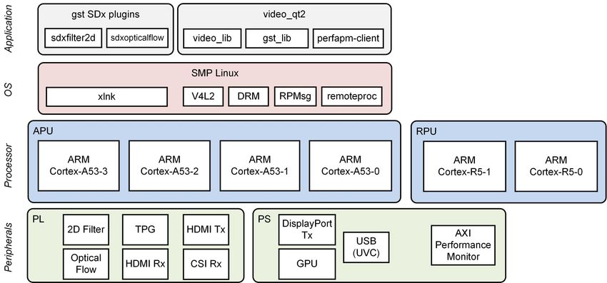
Design Overview
This module shows how to add two image-processing filters between the capture and the display. The 2D filter and dense optical flow algorithm are implemented in hardware using the hardware-optimized xfopencv libaries.
Design Components
This module requires the following components:
- zcu102_base_trd (SDSoC)
- sdxopticalflow (gstreamer plugin)
Build Flow Tutorials
Optical Flow GStreamer Plugin
This tutorial shows how to build the optical flow GStreamer plugin based on the Base TRD SDSoC platform.
Open the existing SDx workspace from design module 8 using the SDx tool.
% cd $TRD_HOME/workspaces/ws_sdx
% sdx -workspace . &
- From the menu bar, select Window → Preferences. From the dialog, select System Project on the left and check the 'Show system projects in workspace' box.

- Click File → New → SDx Library Project from the menu bar. Enter
gstsdxopticalflowas the project name. Change the System project togstsdxfilter2d_systemwhich is the system project that got generated automatically in DM8. Click Next. Select the default "shared library" option and click Next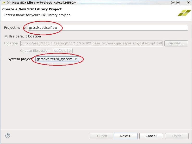
- Change the Runtime settings to C/C++, check the "Sysroot path" box, click browse and enter the path to the Petalinux generated target sysroot:
$TRD_HOME/petalinux/sdk/sysroots/aarch64-xilinx-linux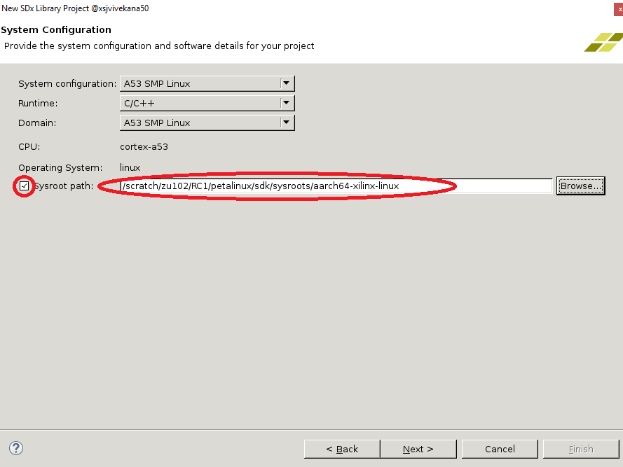
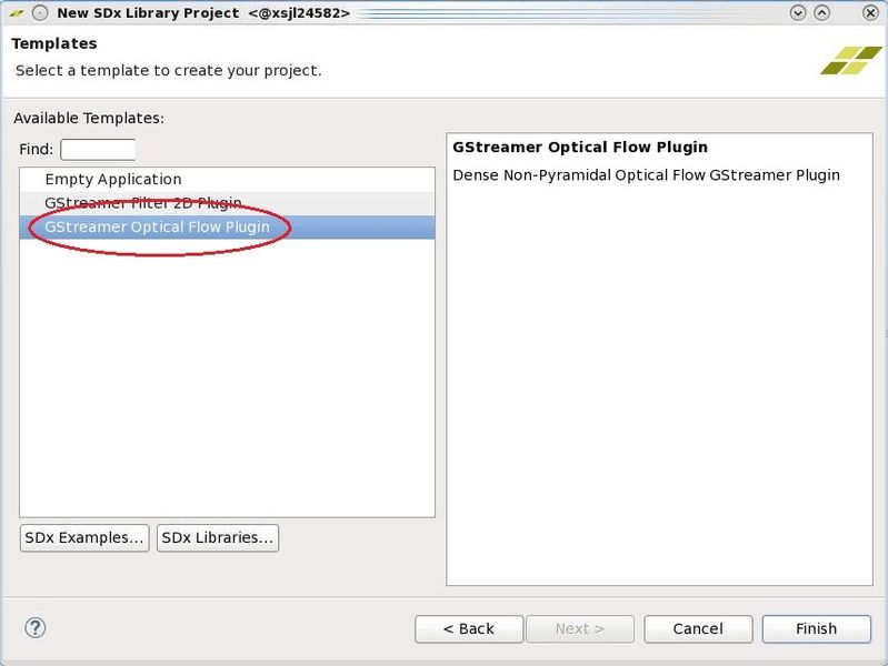
- From the template dialog, select the GStreamer Optical Flow Plugin template and click Finish.
- In the Project Explorer, you can see that the newly generated
gstsdxopticalflowproject was placed under the existing system project namedgstsdxfilter2d_system.
- In the
gstsdxopticalflowproject configuration window, make sure the hardware functions are shown as below. Uncheck the Generate SD card image box.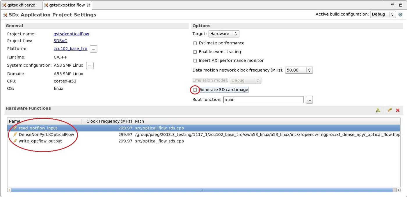
- Right-click the
gstsdxopticalflowproject in the Project Explorer and select C/C++ Build Settings. Under SDS++ Linker → Miscellaneous, enter the string "-mno-bitstream" in the Linker Flags text field. Click Apply and Close.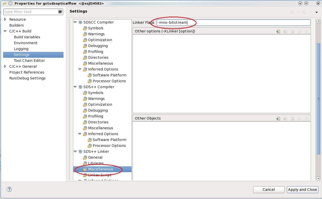
Right-click the
gstsdxfilter2d_systemproject in the Project Explorer and select Build. This will build all sub-projects present in the system project. As thegstsdxfilter2dproject was already built in DM8, the tool will skip to thegstsdxopticalflowproject. The previous selection skips running bitstream and SD card generation for just thegstsdxopticalflowproject but instead builds the system project which includes both accelerators in a single design. This step can take several hours.Copy the generated SD card image once the build is finished.
% cp -r gstsdxfilter2d_system/Debug/sd_card $TRD_HOME/sd_card/dm9
Run Flow Tutorial
- See here for board setup instructions.
- Copy all the files from the
$TRD_HOME/sd_card/dm9SD card directory to a FAT formatted SD card. - Power on the board to boot the images; make sure INIT_B, done and all power rail LEDs are lit green.
- After ~30 seconds, the display will turn on and the application will start automatically, targeting the max supported resolution of the monitor (one of 3840x2160 or 1920x1080 or 1280x720). The application will detect whether DP Tx or HDMI Tx is connected and output on the corresponding display device.
To re-start the TRD application with the max supported resolution, run
% run_video.sh
To re-start the TRD application with a specific supported resolution use the -r switch e.g. for 1920x1080, run
% run_video.sh -r 1920x1080
- The user can now control the application from the GUI's control bar (bottom) displayed on the monitor.
- The user can select from the following video source options:
- TPG (SW): virtual video device that emulates a USB webcam purely in software
- USB: USB Webcam using the universal video class (UVC) driver
- TPG (PL): Test Pattern Generator implemented in the PL
- HDMI: HDMI input implemented in the PL
- CSI: MIPI CSI image sensor pipeline in the PL
- File: Raw video file source
- The user can select from the following accelerator options:
- Passthrough (no accelerator)
- 2D convolution filter with configurable coefficients
- Dense optical flow algorithm (shown in figure)
- The supported accelerator modes depend on the selected filter:
- SW - accelerator is run on A53 (filter2d only)
- HW - accelerator is run on PL
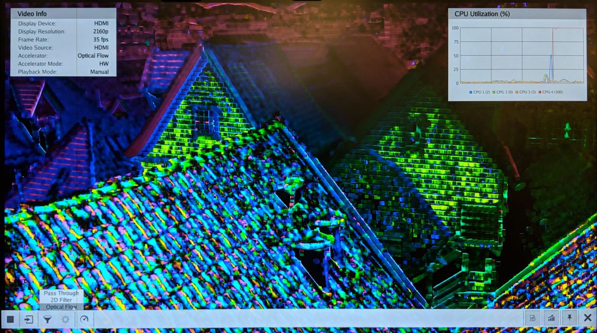
- The video info panel (top left) shows essential settings/statistics.
- The CPU utilization graph (top right) shows CPU load for each of the four A53 cores.
Next Steps
- Continue with Design Module 10.
- Return to the Design Tutorials Overview.
© Copyright 2019 - 2022 Xilinx Inc. Privacy Policy