This page provides a walkthrough of the Built-In Self Test (BIST) and Board GUI/System Controller UI (BUI/SCUI) for Zynq Ultrascale+ MPSoC evaluation boards.
This guide applies to the following boards. User guides for each board are also linked below.
The BIST may be used to verify board functionality. Clocks and other configurable settings can be programmed through the Board GUI.
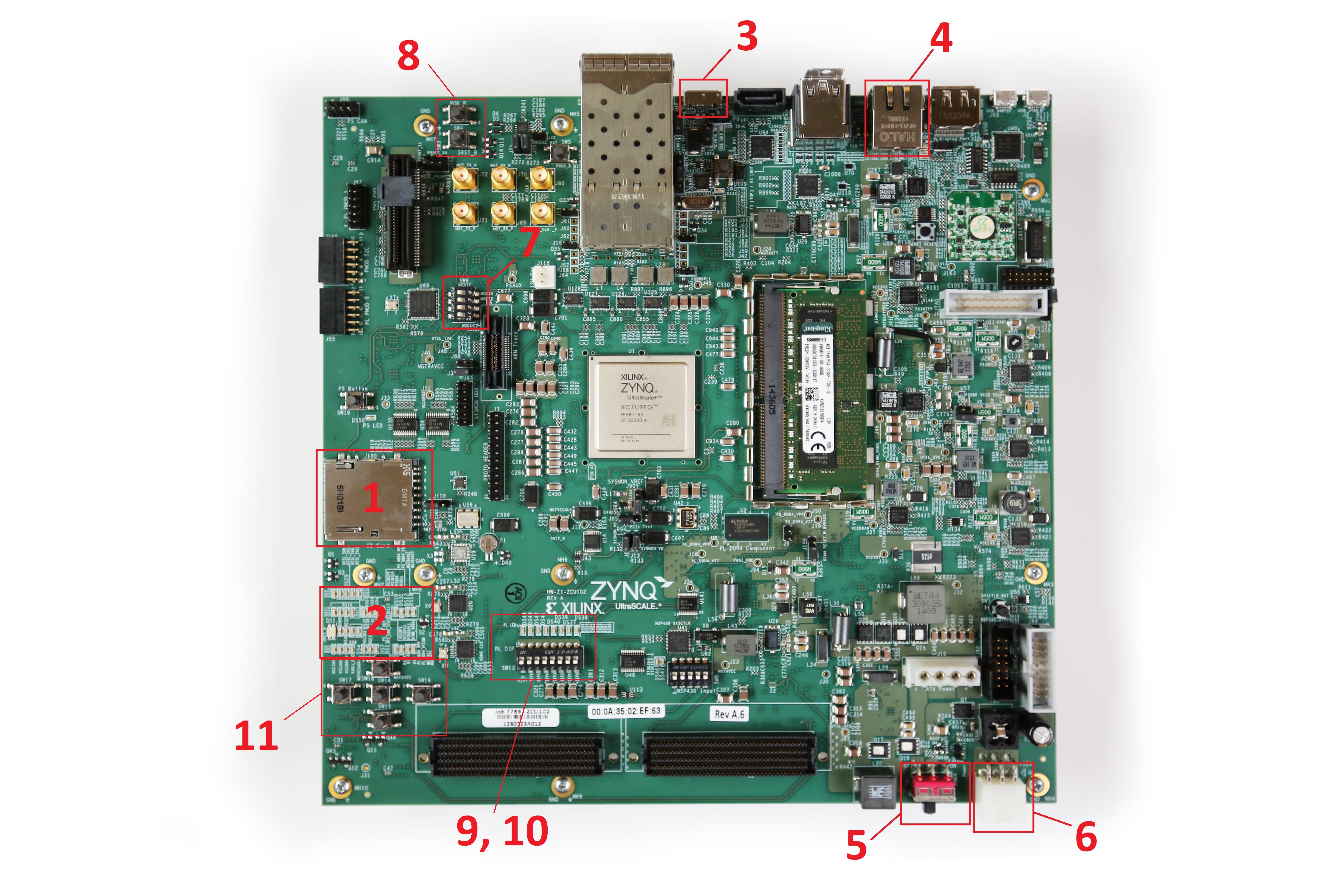
Instructions apply to all boards but board layout will vary. Reference callouts when setting up.
PC connectivity is not necessary to run this BIST.
Verify hardware setup—see User Guides for each board above. Board should be powered off at the start of these instructions.
Set mode switch SW6 to 0010 (QSPI32). See available boot modes below.
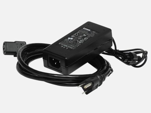
Connect to power and the board’s 6-pin power supply (J52) and power on board. The kit will include an cable and power adapter for this purpose, as shown in the image below.

Power Check: The three rows of Power Good LEDs should glow green, indicating a good power system.
Note: Descriptions for each power and status LED are available in each board’s user guide provided at the top of this page. Refer to the table below to find the location of the descriptions for each board.
Board | Table # | Page |
|---|---|---|
ZCU102 | 3-34 | 82 |
ZCU104 | 3-25 | 68 |
ZCU106 | 3-36 | 89 |
The DONE LED will glow green if/when the board is configured correctly.
The built-in self-test begins after board startup.
Pressing the POR_B switch or the SRST_B switch will turn off DONE LED, reconfigure board and restart BIST.
Each test in the BIST corresponds to a PL LED (see callouts) which lights up (green) when the test is passed. The full BIST will pass when all LEDs have lit up green.
Note:
The Clock/Clocking and Memory, BRAM, PL-DDR4, PS-DDR4, Flash, EEPROM, and I2C tests run without user input.
For the DIP switch test (SW13, see callouts), all DIP switches must be turned to the ON position and then back.
For the pushbutton (PB) test, the four directional buttons (N, W, S, and E) can be pressed in any order as long as the center button is pushed last.
If a test is waiting to receive any user input, its corresponding LED will flash on and off slowly. When the device begins to receive input, it will flash quickly until all necessary inputs for that test have been received (e.g., all buttons pressed).
Refer to the table below for each board’s tests and PL LED test assignments. The tests will not necessarily run in LED # order/the order they are shown in this table.
Board | LED | Test |
|---|---|---|
ZCU102 ZCU106 | 7 | Clock |
6 | BRAM | |
5 | PL-DDR4 | |
4 | PS-DDR4 | |
3 | Flash | |
2 | I2C | |
1 | DIP | |
0 | PB | |
ZCU104 | 3 (Top left) | Clocking and Memory |
2 (Top right) | EEPROM and I2C | |
1 (Bottom left) | DIP | |
0 (Bottom right) | PB |
More comprehensive component lists available in board user guides.
SD Card Interface
Power and Status LEDs
USB Interface
Ethernet Interface
Power On/Off Switch
Power Connector
Mode Configuration Switch (SW6)
POR_B and SRST_B Switches
PL LEDs
PL DIP Switches
Pushbuttons


The following table can be used to determine mode switch configuration. Zynq Ultrascale+ MPSoC devices use switch SW6 for boot configuration. Refer to individual board callouts to locate switch.
Boot Mode | Mode Pins [3:0] | SW6 [4:1] |
|---|---|---|
JTAG | 0000 | ON, ON, ON, ON |
QSPI32 | 0010 | ON, ON, OFF, ON |
SD | 1110 | OFF, OFF, OFF, ON |
The board GUI allows users to change certain settings, set boot-up configurations, and further debug device issues. The guide below provides an explanation for starting and navigating the board GUI.
Download necessary files for board SCUI below.
The GUI can be started by running BoardUI.exe in the unzipped folder.
The serial number for your board can be chosen in the next window.
Navigate to the Clocks > Set tab and set the frequency for Si5328 to 156.25 MHz.
In the Clocks > Read tab, verify the frequencies have been set correctly with the “Read ___ User Frequency” buttons.
If the frequencies are not as expected, the clocks should be set to default. Clocks can be reset to default by pressing their corresponding buttons in the Clock > Restore Device Defaults Tab.
Clock frequencies can also be be set at boot-up in the Clock > Set Boot Frequency Tab. Note: These settings will override device defaults at boot-up.
Board voltages can be checked in the Voltages tab.
Power values can be verified with either default or custom values in the Power > Use Default Calibration and Power > Use Custom Calibration tabs respectively.
INA226 Registers can be set and checked similar to clocks in the Power > Set INA226 Registers and Power > Get INA226 Registers tabs respectively.
The 4-bit GTR MUX setting can be changed and verified in the GTR MUX tab.
The VADJ voltage can be set in the GUI, or set to configure at boot-up in the FMC > Set VADJ > Current and FMC > Set VADJ > Boot Up tabs respectively. Note that some board interface tests expect a VADJ setting of 1.8V, which is the default setting.
The HSPC clock can be set in the FMC > HSPC > Clock tab.
Board information, including board name, revision, serial number, and MAC address can be returned by running all options in the EEPROM Data tab.
If using an FMC+ card, EEPROM data can be returned in a separate window using the button in the FMC > HSPC > EEPROM tab.
The following operations can be run from the GPIO Commands tab to verify functionality.
Blink LEDs
Return state of DIP switch
Return PMU state
Return PS GPIO state
Return PL GPIO state
Board Schematics (Links below lead to downloads at the Xilinx website)
Board Product Pages
Zynq Ultrascale+ MPSoC Targeted Reference Designs (TRD) Page